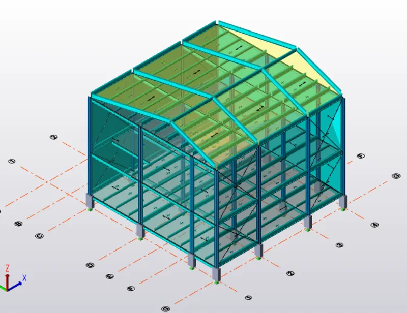
To model beams and bracings for industrial steel structures using TSD
1. Create beam properties for First floor and model the beams
Ans :-
Aim :- To Create Beam Properties And Model Primary And Secondary Beams On The Ground floor , First
Floor , Roof Level
Introduction :- Tekla Structure , Basic Building Objects Are Provided And Detailed Further. Columns Beams Is
Modelled And properties Are Assigned Such as Materials , Alignments , Supports Design Code Etc. Certain
Configurations Are Assigned Before Modelling The Objects Such As Design Code , Analysis Type , Scenes , Materials
Etc.
Procedure :-
- Open Tekla Software
- Click On Mange Property Sets
- Click On New
- Select Steel Beam
- Create Three Types Of Beams And Assign Steel Beam Proprtie
- Three Types Of Beams Are taken : Beam 1 - ISMB250 , Beam 2 - ISMB350 , Beam 3 - ISMB500
- Untick Autodesign In Each Of The Beams
- Major Alignment Is Taken As Bottom In The Beams
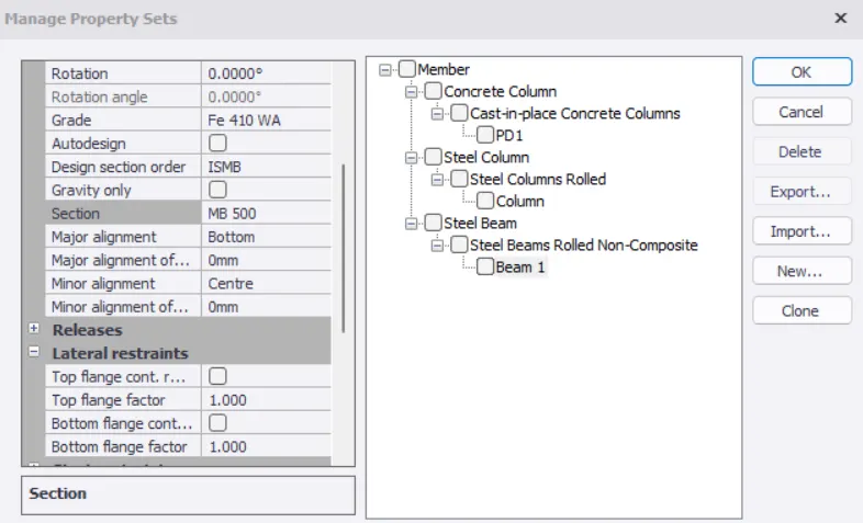
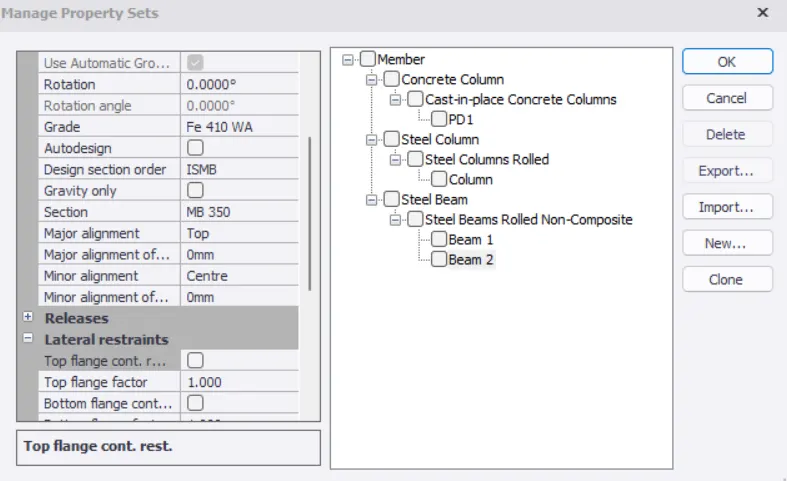
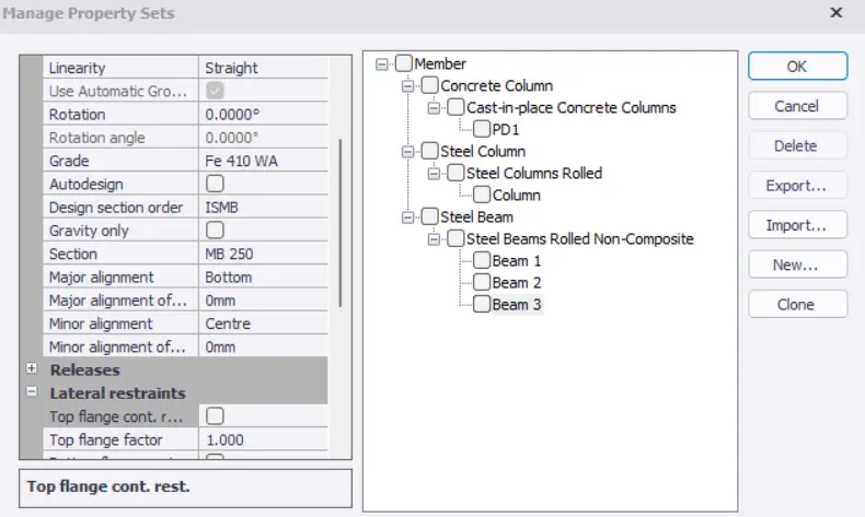
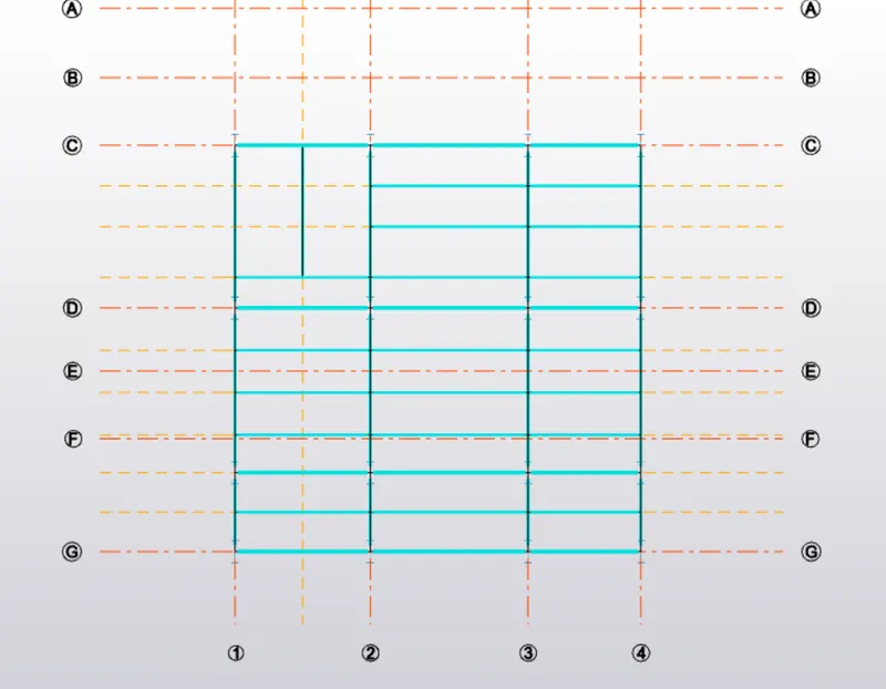
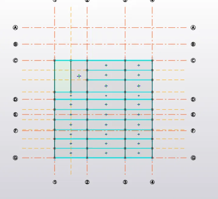
- Now Place Beams At The First Floor
- MB 500 Beams Are Placed Horizontally On Plan
- MB 350 Beams Are Placed Vertically On Plan
- MB 250 Beams Are Placed As Secondary Beams
Results :-
2. Create rafter beam on second floor as roof and moment frame action in one direction and add bracings at
locations as per the design intent
Ans :-
Aim :- 1. Create Rafter On Second Floor As Roof And Moment Frame Action In One Direction
2. Add Bracings At Suitable Locations
Introduction :-
Bracing System : Function Of Bracing Is To Provide Stability And Resist Lateral Loads , Either From
Diagonal Steel Members Or From a Concrete ' Core '. For Bracing Frames , Beams And Columns Are Designed Only
To Support Vertical Load , Since The Bracing system Should Carry All Lateral Loads.
Rafters : A rafter Is A Structural Component That Is Used As Part Of a Roof Construction . Typically , It Runs from
The Ridge Or Hip Of The Roof Of The Wall Plate Of The External Wall .
The Ridge Beams Is The Horizontal Timber Beams At The Apex Of The Roof . It Has No Structural Function But Is
The Member Against Which The High Ends Of The Rafters Lean . It Ensures That The Rafters Meet In A Straight
Line And Stay Upright .
Procedure :-
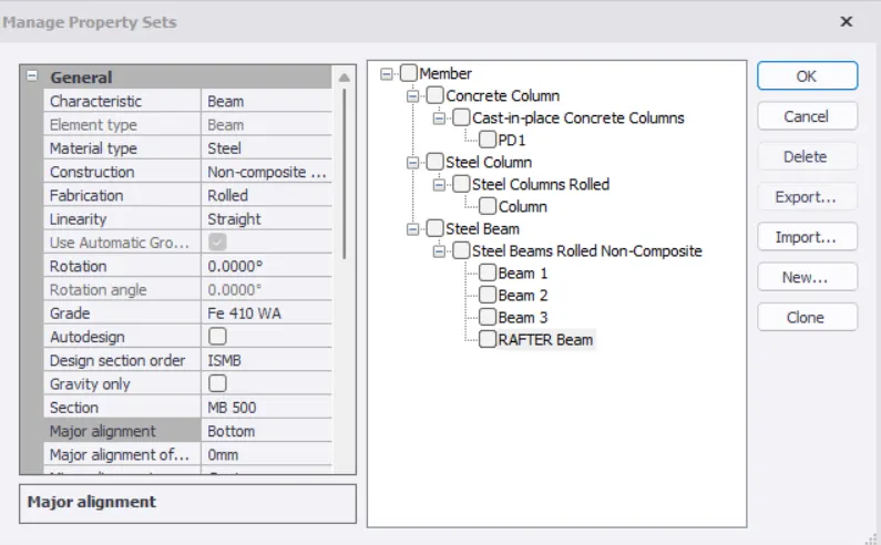
- Go To Model tap
- Go To Manage Property Set
- Assign Properties To The Beam : Section Is ISMB 500 , Untick Autodesign , Major Aligment Is Bottom And Under
Releases Both Ends Are Fixed
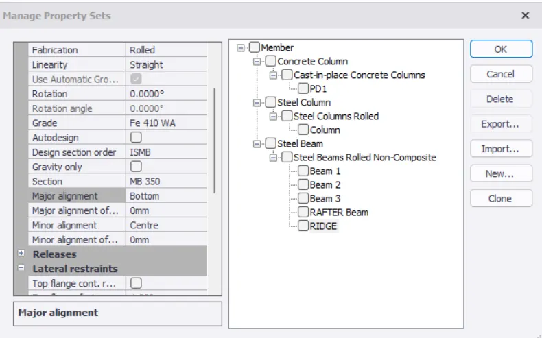
 - Create Another Steel Beam : Ridge Beam
- Assign properties To The Beam : Section Is ISMB350 , Untick Autodesign And Major Aligment Is Bottom
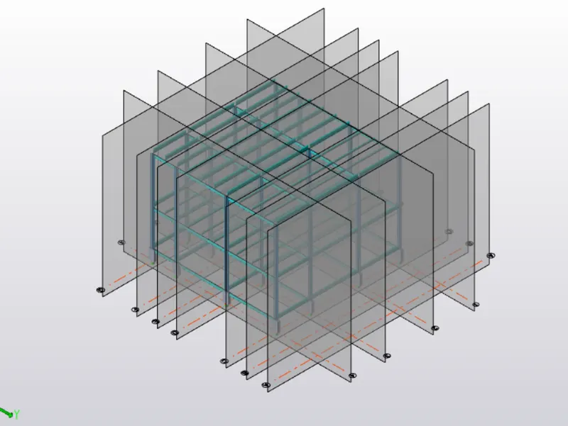
 - Now Click On Frames
- Select All The Grids And Assign Frames.
 - Now Open FRAME 4
- Draw Construction Line At Midpoint Between Grids E And F
- Draw Another Construction Line Above Firrst Floor Level As Show Below 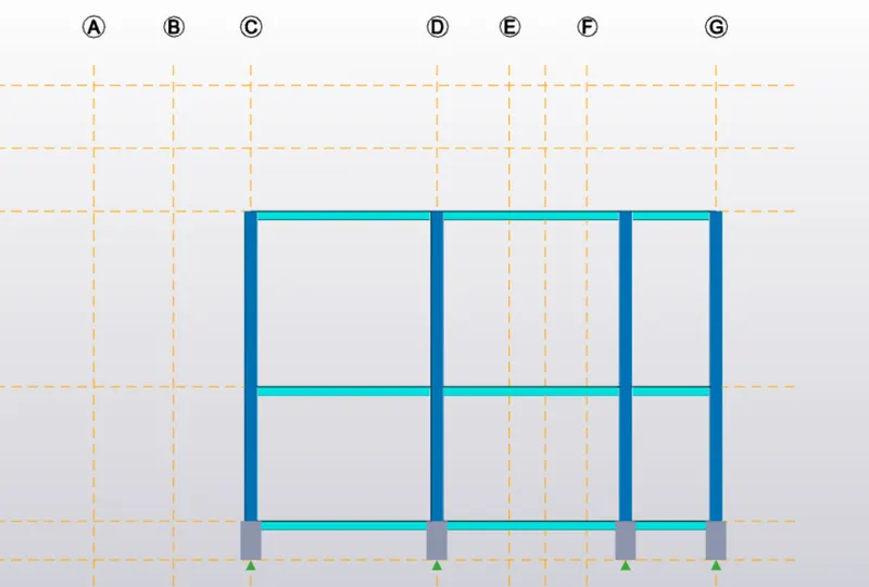
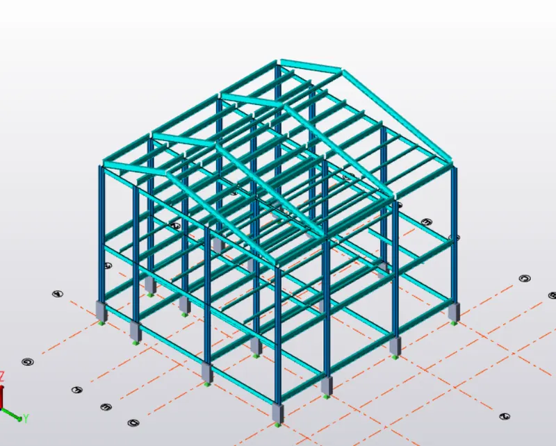
- From The Intersecting Point Draw Rafter Beam Connecting To Both The End Points
- Draw Similar Rafter Beams At Remaining Grids
- Now Place Ridge Beam On Top Of The Rafter Beams.
 - Go To Manage Property Sets
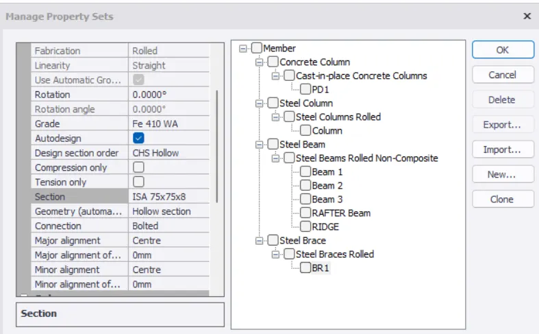
- Add New Member : Steel Brace
- Assign Section As : Equal Angle 75X75X8 Size And Connection As Bolted , Untick : Autodesign
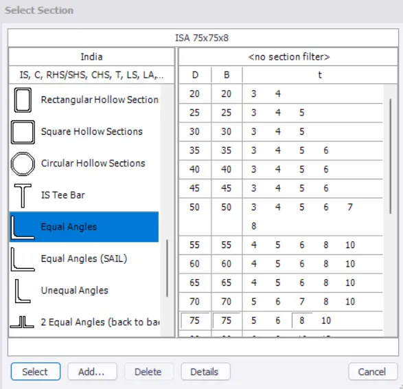
 - Select Brace - X From Model And Draw Bracings In Frame C And G As Shown Below.
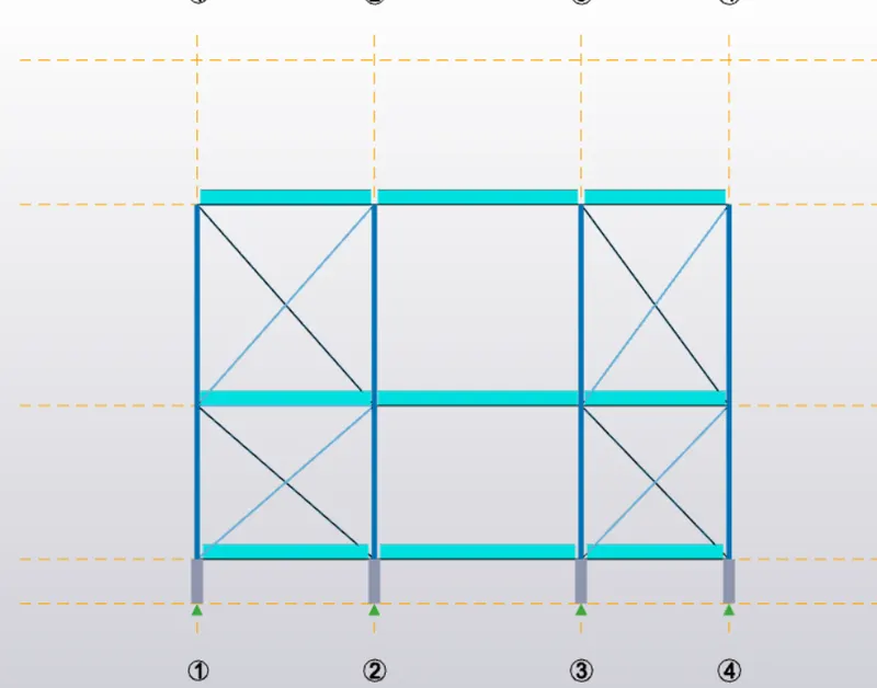 - Go To Model And Click On Wall Panel
- Draw Wall Panels At Frame c , G As shown Below 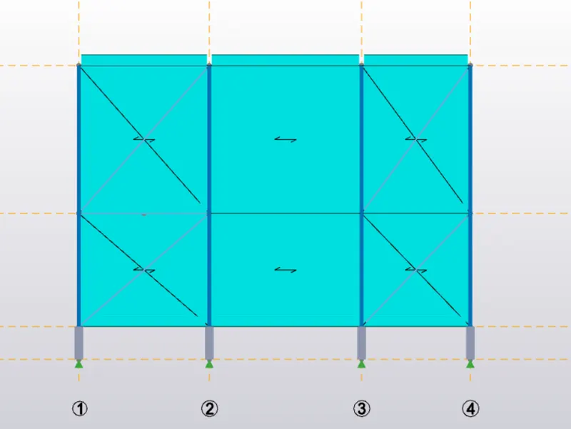 - Similarlt Draw Wall Panels At Grid 1 And 4
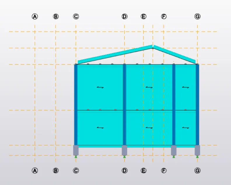 - Now Click On Roof Panel In The Model Tob And Draw roof Panels At Rafter Beams
- Go To Manage Property Sets
- Click On New And Create Slab item
- assign Properties To The Slab : Slab type : Slab On Beams , Decomposition : Twoway , Depth Taken As 200mm ,
Grade Taken As M25
- Untick Autodesign
- Reinforcement Details : For Tap And Bottom Bars ( Both Inside And Outside )
- Bar Size 10mm
- Bar Spacing 150mm
- After Assigning Properties , Go To Model : Click On slab On Beams.
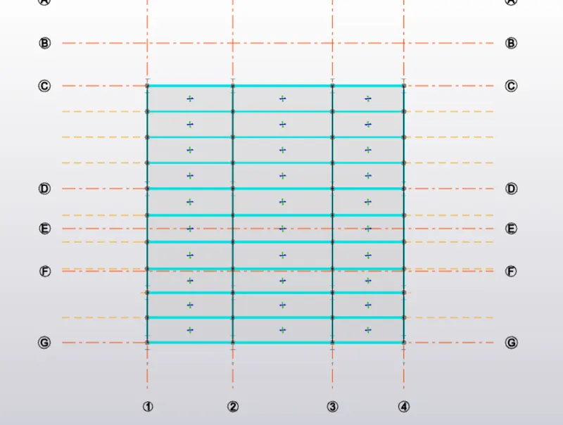
- Assign Slabs In The Ground Floor , First Flooor And Top Floor ( Angle 90 )
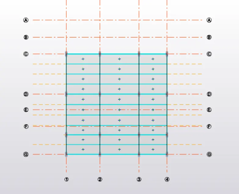
 Result :-