To Generate seismic loading based on IS code and to run the analysis using TSD
1. Generate seismic loading based IS codal provisions and zone II. Any other data you can assume and input accordingly.
AIM: To generate seismic loading based IS codal provisions and zone II.
INTRODUCTION:
- Seismic load indicates how much seismic energy (waves of energy that travel through the earth) a structure would need to endure in a specific geographic location.
- In tekla software it is generated within the software itself using seismic wizard option in load toolbar.
PROCEDURE:
STEP: 1
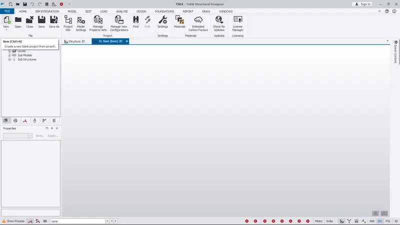
- Open TDS software
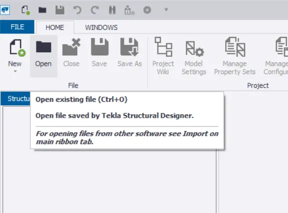
- click on open:
- open the file from privious
STEP: 2
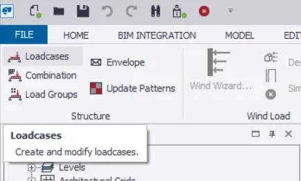
- Now go to the load cases
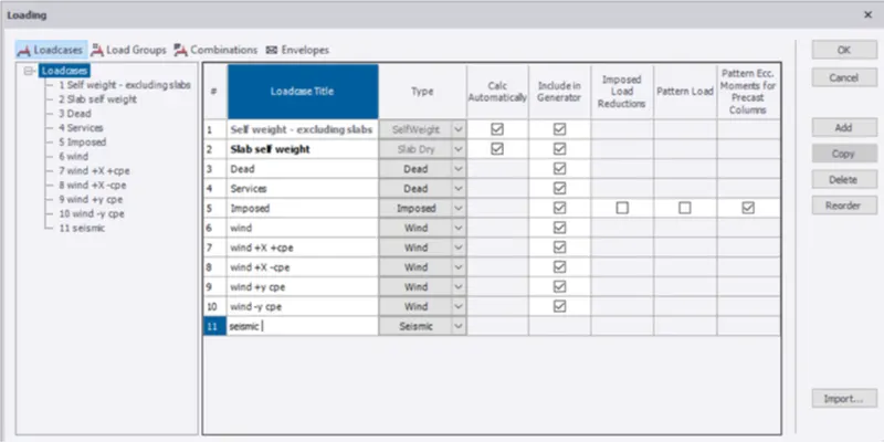
- Click on ADD
- Add the seismic load case, and click ok
STEP: 3
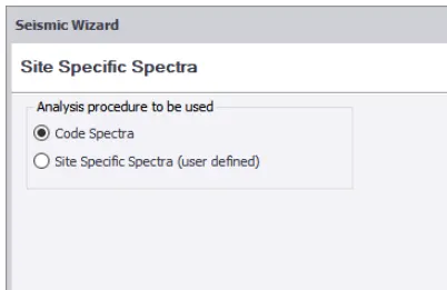
- Now go to the seismic wizard and select code specta and click Next.
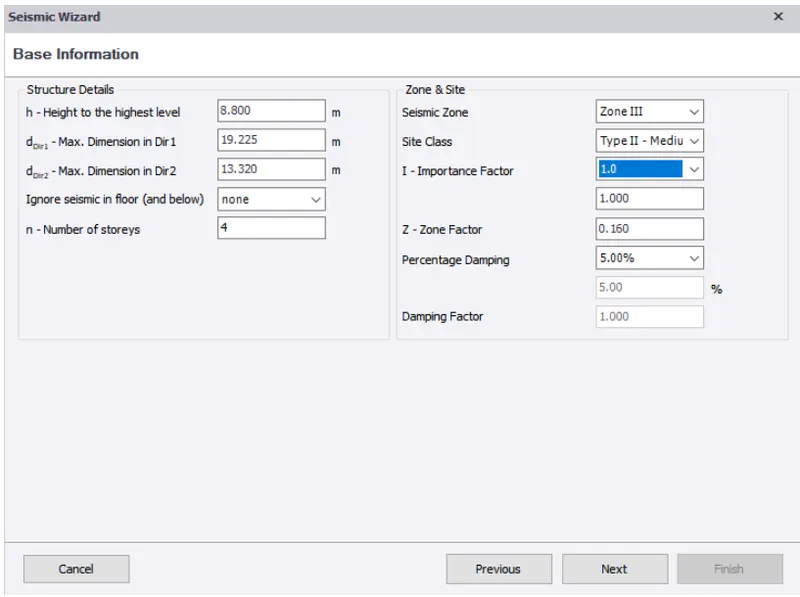
- Now enter the zone and click Next
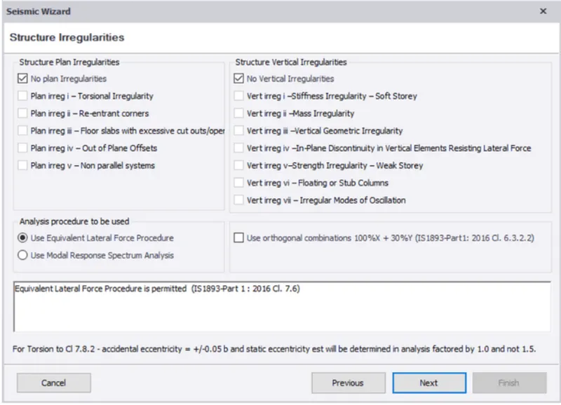
STEP: 4
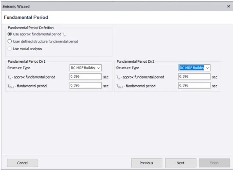
- Now we have to enter the structure type as RC MRF building, and click Next.
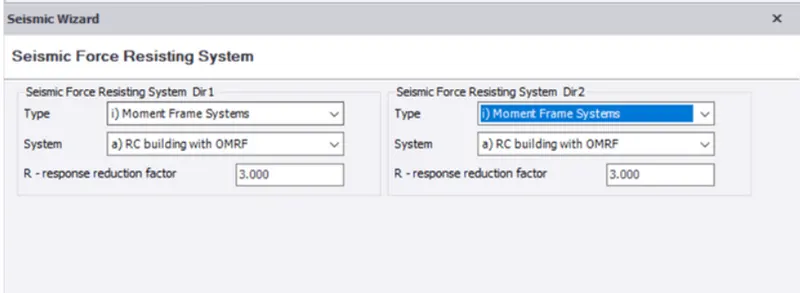
STEP: 5
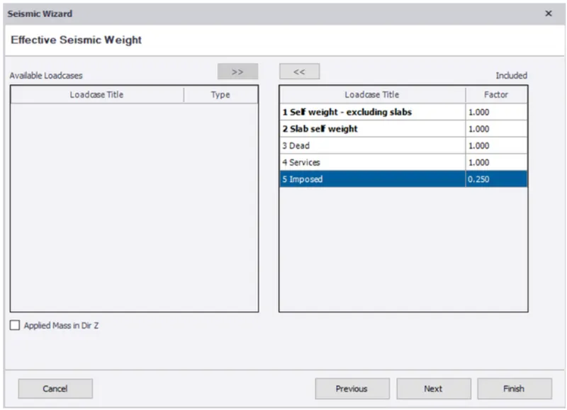
- Now include the load cases and click Next.
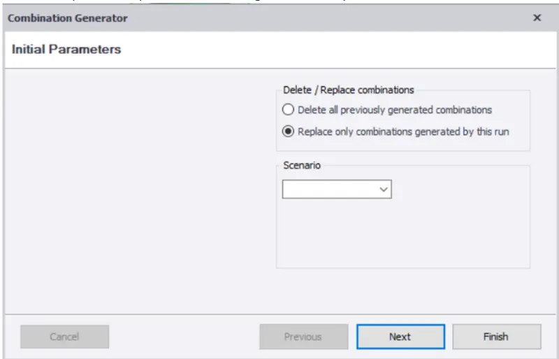
- Select "Replace only combinations generated by this run" and click Next.
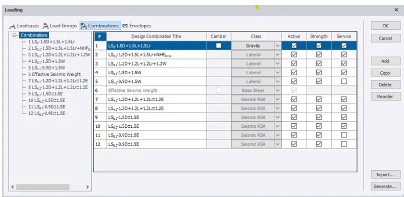
- Now all the load cases are generated.
- Suitable load cases can be selected and applied on the model, and click Next.
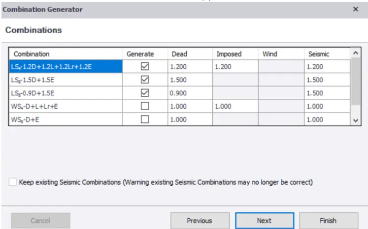
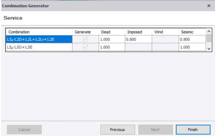
- Now provide the combinations and click Finish
RESULT:
HENCE, The seismic load is defined and generated in the software.
2. Run the analysis. Summarize your understanding of the analysis results.
AIM: To Run the analysis and summarize your understanding of the analysis results.
INTRODUCTION:
Analysis of a structure is post modeling step to verify that wheather the structure is designed for the member satisfy the code proviisonal or not.
PROCEDURE:
STEP: 1
- Open TDS software
- click on open:
- open the file from privious
STEP: 2
- Go to analyses
- Click on "setting" ->1st order analyses.
- Check for modification factor for concrete and tsee.
- Initially for first analyses,it should be 1{If any other values change to 1.}
- Click on first order analyses,
- Analyses will run.
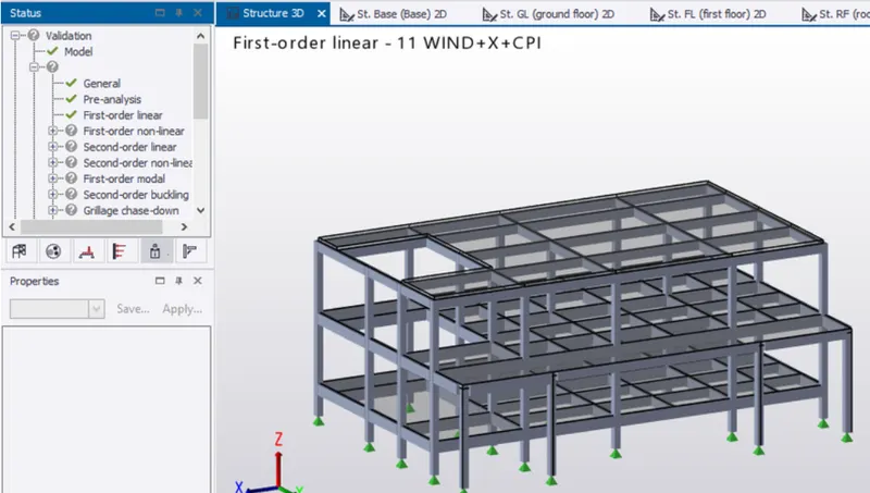
- At bottom right corner,click on result view.
- Select individual frame,select the beam first and right click.
- Now check selection/member.
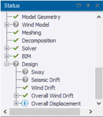
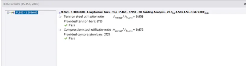
- Check if it pass all criteria,if not see the property and change the member.
STEP: 3
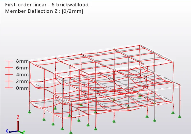
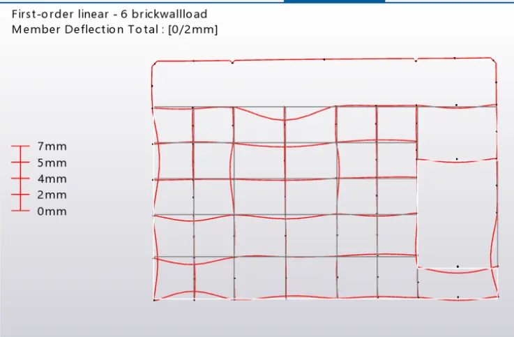
- In result view mode,the maximum deflection is 14mm at first floor near corridor (additional support can be provided).
- It is within the limits,hence ok.
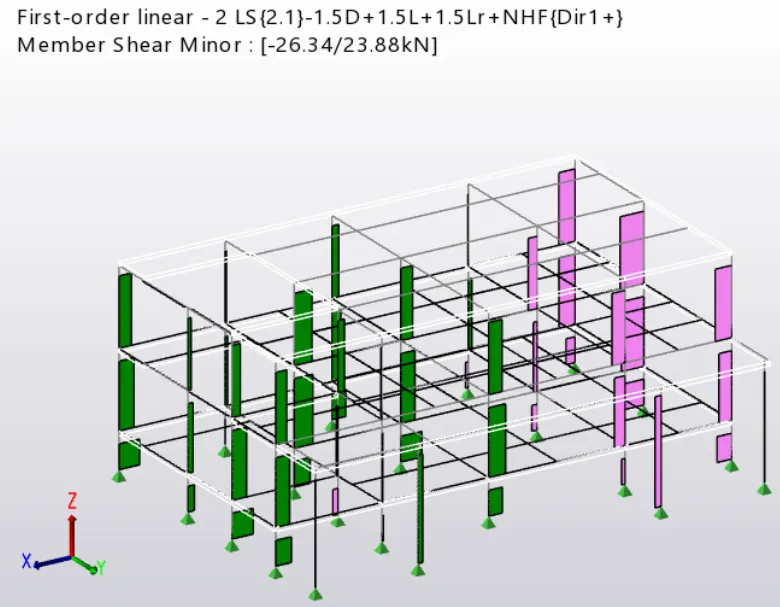
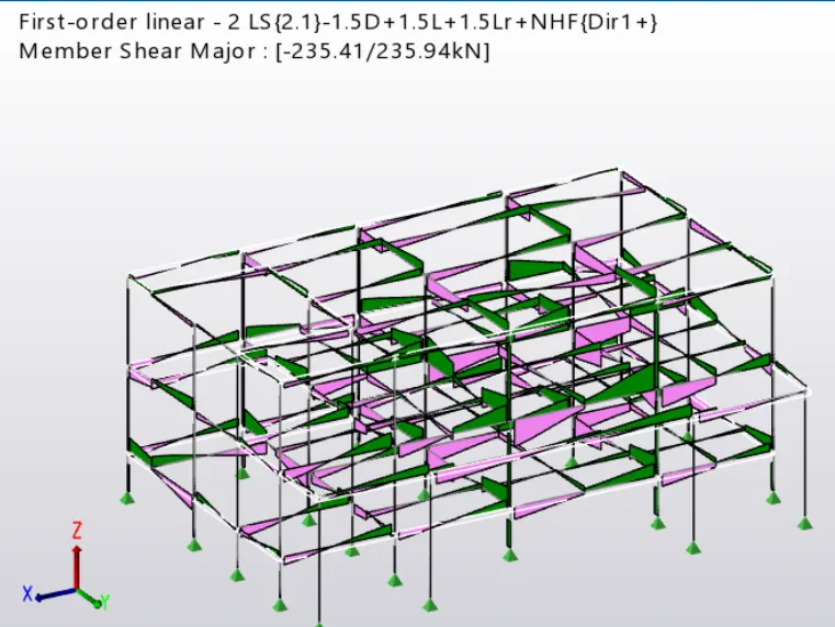
SHEAR FORCE
- shear force of the column is same as ideal,hence ok.
BENDING MOMENT
- bending moment of the beams and column are minor,hence ok.
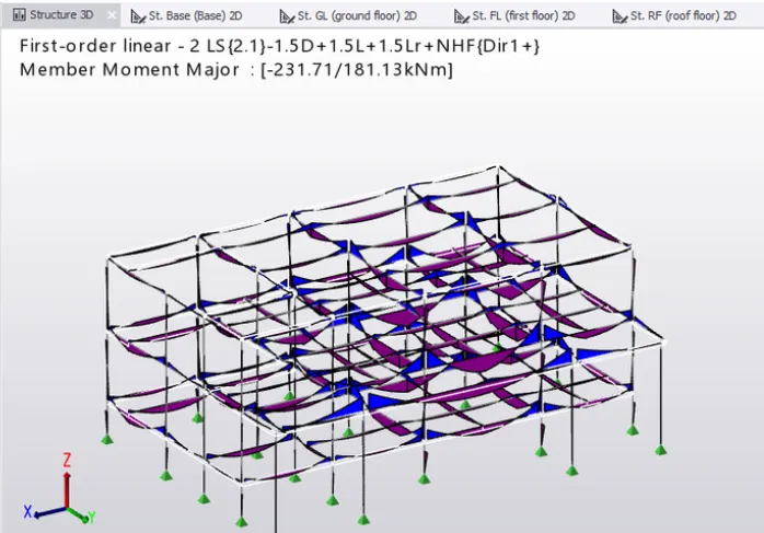
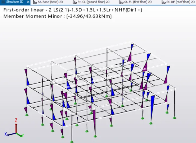
- The beam and column member have passed the check,

RESULT:
HENCE, The model is analysed and output of analysis is summarized.