To calculate the dead , live and wind load for RC residential structure and to apply them using TSD
Que :- 1. Calculate dead load in design report based on IS code and apply dead load on the model
- Finishes of 50mm
- Slab thickness as per the design
- Brick wall load
- Roofing load
Ans :-
Aim : To Calculate Dead Load In Design Report Based On IS Code And Apply Dead Load On The Model
Introduction :-
Dead Loads, Also Known As Permanent Or Static loads, Are Those That Remain Relatively Constant Over Time And Comprise, For
Example, The Weight Of A Building's Structural Elements, Such As Beams, Walls, Roof And Structural Flooring Components.
Constant
Load In A Structure (Such As a Bridge , Building, Or Machine) That Is Due To The Weight Of The Members, The Supported
Structure, And Permanent Attachments Or Accessories
Procedure :
- Finishes Of 50mm
- Slab Thickness As Per The Design
- Brick Wall Load
- Roofing Load
Finish Loading :-
Finish Load=0.5 X 24=1.2kN/m2
Slab Loading :-
Slab Load Will Be Generated Within The Softwara
Brickwall + Cement Plaster Thickness 230mm
Brickwall Loading :-
GL-Ist Gloor-0.23X20X3.2=14.72KN/m8
Same For 1st Floor-Roof Level
Roof Loading :-
Roof Level-(Paraphet Wall Height Is 900mm And Thickness 155mm)=0.155X0.9X20=2.79kN/m^3
Roofing Load-Finish Floor-1.2kN/m2
Load Applied On Model :-
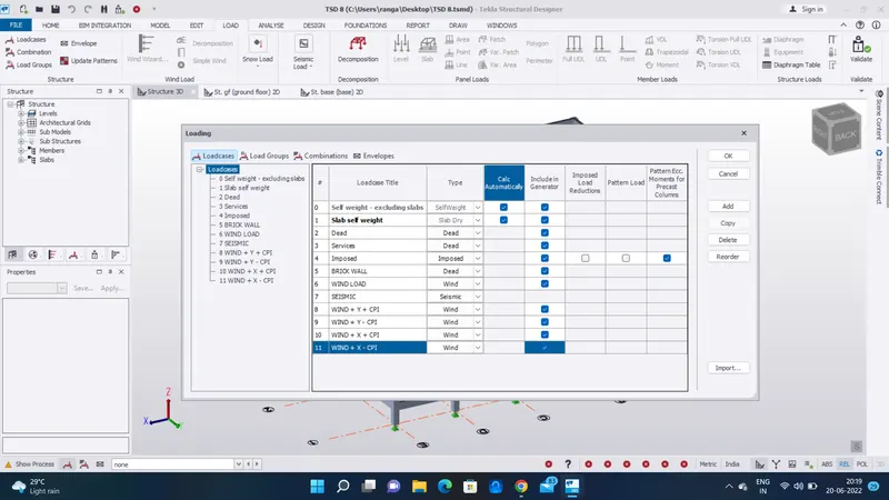
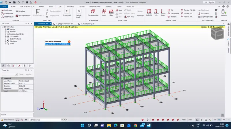
-First We Want To Create A Load Cases
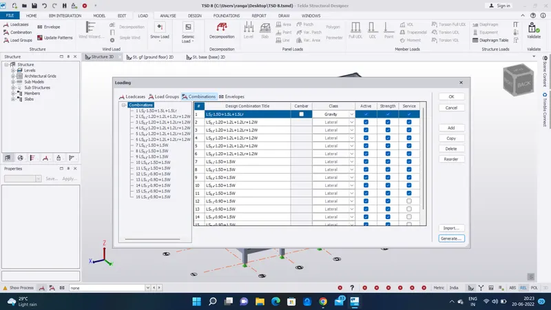
- Next We Want To Create A Load Combination With Use Of Generate Option
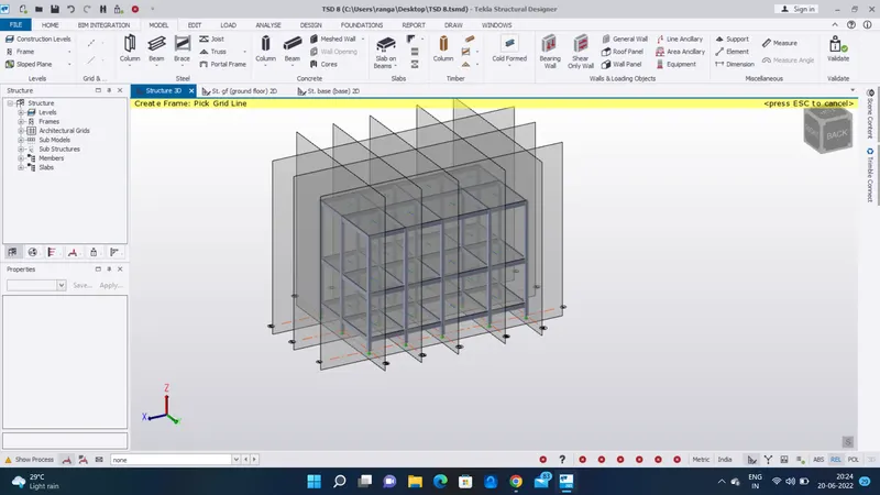
- Next We Want To Create A Frame With Use Of Frame Option
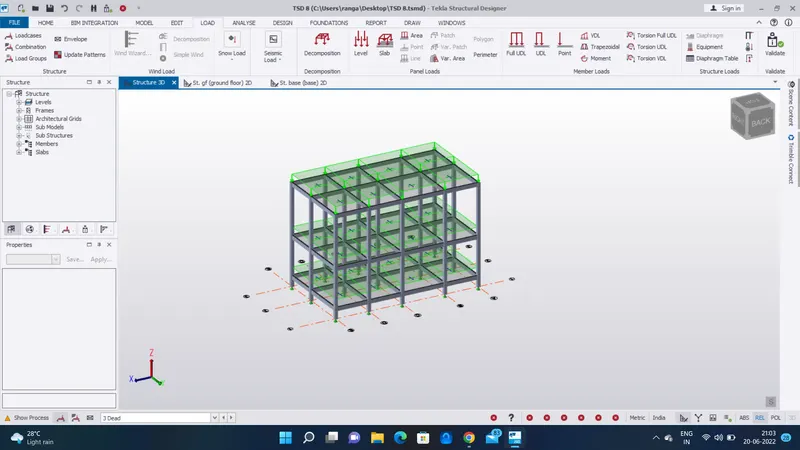
- Next Select The Dead Load On Bottom Of The Screen
- And Select The Area Load
- Apply The Dead Load 1.2 Kn/m^2
- Next We Want To Apply The Brick Wall Load = 14.72 kN/m^2
- The Applied Load As Been Shown Below
Result :-
As Per The Question To Calculate Dead Load In Design Report Based On IS Code And Apply Dead Load On The Model Is
Completed
Que :- 2. Calculate live load in design report based on IS code and apply dead load on the model
Ans :-
Aim : To Calculate Calculate Live Load In Design Report Based On IS Code And Apply Dead Load On The Model
Introduction :-
Live Load Is A Civil Engineering Term For A Load That Is Not Constant, But Changes Over Time. Live Loads Can Be Caused By
Anything
Adding, Removing, Or Relocating Weight On A Structure. This Includes People Walking Across A Surface And Objects That Can
Be Moved Or Carried.
Live Loads (Also Known As Applied Or Imposed Loads, Or Variable Actions) May Vary Over Time And Often Result From The
Occupancy Of A Structure. Typical Live Loads May Include; People, The Action Of Wind On An Elevation, Furniture, Vehicles, The
Weight Of The Books In A Library And So On
Procedure :-
AS Per IS 875 - Part 3,The Given Live Loads Are:
- Office=3 KN/m^2
- Reception=3 KN/m^2
- Meeting Room/Conferece Room-4 kN/m^3
- Equipment Room =10 KN/m^2
- Toilets=2 KN/m^2
- Store Room= 5 KN/m^2
- Staircase =3=4 KN/m^2
- Lobby =3 KN/m^2
- Cooridor=4 KN/m^2
- Roof (Accessible) =1.5 KN/m^2
Load Applied On Model :-
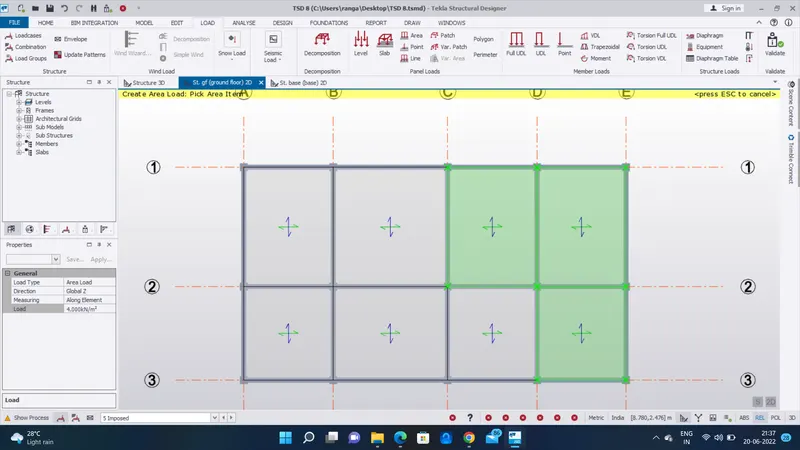
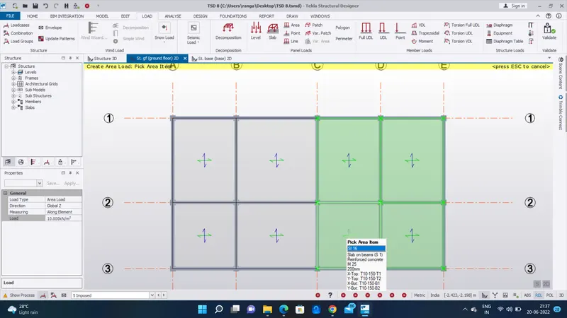
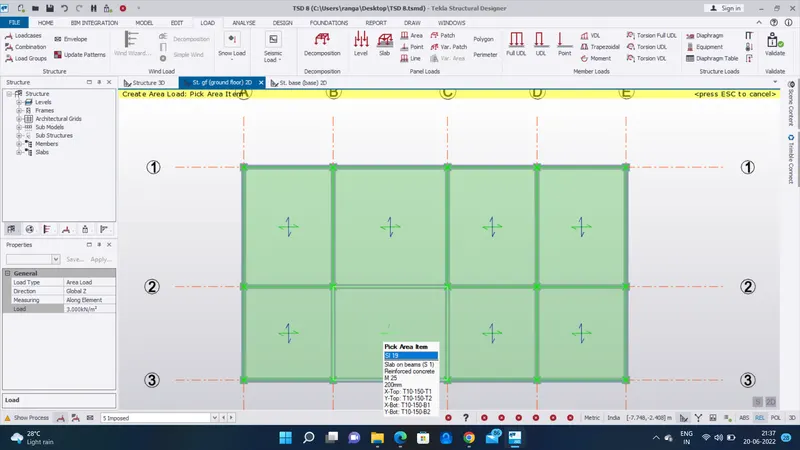
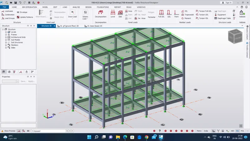
- Next We Want To Apply The Imposed Load
- Go Select The Imposed Load On Bottom Of The Screen
- As Per The IS 875 Rules The Imposed Load As Been Applied
- First Go To The Area Load Under The Modal Tab
- Finally Apply The Load
Result :-
As Per The Question To Calculate Live Load In Design Report Based On IS Code And Apply Dead Load On The Model Is Complete
Que :- 3. Generate manual wind loading in the design report based IS code as per the following input
- Basic wind speed = 50m/s
- Terrain category 2
Ans :-
Aim : To Generate Manual Wind Loading In The Design Report Based IS Code As Per The Following Input
Introduction :-
Wind Load Is The Load, In Pounds Per Square Foot, Placed On The Exterior Of A Structure By Wind. This Will Depend On : The
Angle At Which The Wind Strikes The Structure. The Shape Of The Structure (Height, Width, Etc.). Armed With Pressure And
Drag Data, You Can Find The Wind Load Using The Following Formula: Force = Area x Pressure x Cd. Using The Example Of A
Flat Section Of A Structure, The Area – Or Length x Width – Can Be Set To 1 Square Foot, Resulting In A Wind Load Of 1 x 25.6
x 2 =51.2 psf For A 100-mph Wind.
Procedure :-
Given data :
- Basic wind speed = 50m/s
- Terrain category 2
- Total length of the building (l) = 19.225m
- Total width of the building (w) = 10.700m
- Total height of the building (h) = 16.8
- Class of the structure = Class A
- Life of the structure = 50 Years
- l/w = (19.225/10.700) = 1.79
- h/w = (16.8/10.7) = 1.5
Step 1 :-
EXTERNAL PRESSURE CO-EFFICIENT (Cpe)
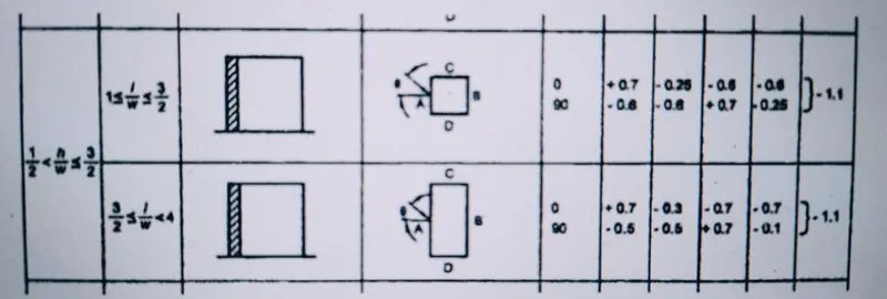
As Per The IS 875 Part 3, Table 5
Building Height Ratio
Building Height Ratio = 1/2<h/w<3/2
= 0.5<1.5<1.5
Therefore, The Building Plan Ratio = 3/2 < l/w < 4
= 1.5 < 1.79 < 4
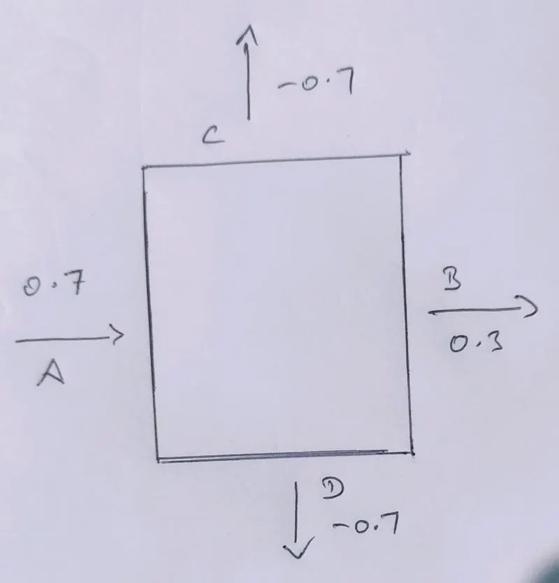
Hence The Plan We Choose Is Given Below
STEP :2
Finding The Factors (k1, k2, k3, k4)
k1:
From Table 1 For The Basic Wind Speed For 50 m/s,
Risk Coeffiecent, K1 = 1.0
K2 :
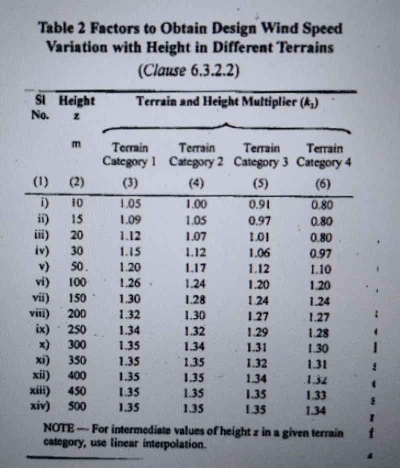
From Table 2,
16.8m Height = Terrain Category 2
20m Height = 1.07
By Using The Interpolation Method,
k2 = 1.05
K3:
Topography Factor, k3 = 1 (From clause 6.3.3)
K4:
Importance Factor K4 = 1 (From Clause 6.3.4)
STEP :3
Vz=Vb x k1 x k2 x k3 x k4
= 50x1x1.05x1x1
= 52.5 m/s
STEP :4
Pz = 0.6 Vz^2
= 0.6 x 52.5^2
= 1653.75 N/sq.m
= 1.653 kn/sq.m
STEP :5
Wind Direction (Up To Roof Level) Y-Direction :
1.) Wind Direction Along y- Direction (Face A):
| Cpe + | Cpi - | |
| Height of the building | 16.8m | 16.8m |
| External pressure co-efficient Cpe | 0.7 | 0.8 |
| Internal pressure co-efficient Cpe | 0.5 | -0.5 |
| Net pressure co-efficient Cp = Cpe - Cpi | 0.2 | 1.2 |
| Design wind pressure, Pz | 1.984 | 1.98 |
| Wind load on Wall (Cp x Cz) Kn/m^2 | 0.4 | 2.38 |
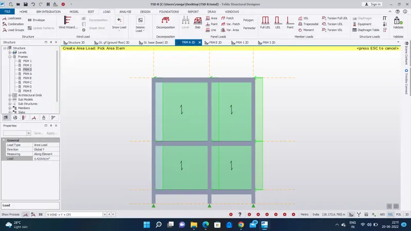
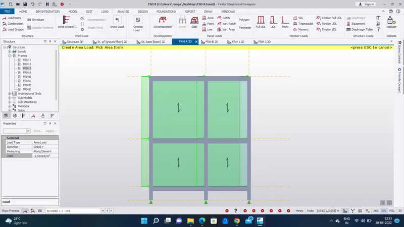
| Factor loading (1.05) | 0.42 | 2.5 |
2.) Wind direction along Y- direction (Face B):
| Cpe + | Cpi - | |
| Height of the building | 16.8m | 16.8m |
| External pressure co-efficient Cpe | -0.3 | -0.3 |
| Internal pressure co-efficient Cpe | 0.5 | -0.5 |
| Net pressure co-efficient Cp = Cpe - Cpi | -0.8 | 0.2 |
| Design wind pressure, Pz | 1.984 | 1.984 |
| Wind load on Wall (Cp x Cz) Kn/m^2 | -1.587 | 0.4 |
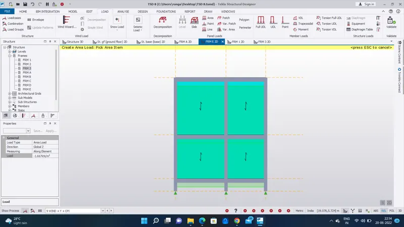
| Factor loading (1.05) | -1.667 | 0.42 |
3.) Wind direction along Y- direction (Face C&D):
| Cpe + | Cpi - | |
| Height of the building | 16.8m | 16.8m |
| External pressure co-efficient Cpe | -0.7 | -0.7 |
| Internal pressure co-efficient Cpe | 0.5 | -0.5 |
| Net pressure co-efficient Cp = Cpe - Cpi | -1.2 | -0.2 |
| Design wind pressure, Pz | 1.984 | 1.984 |
| Wind load on Wall (Cp x Cz) Kn/m^2 | -2.38 | 0.4 |
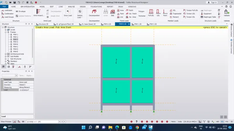
| Factor loading (1.05) | -2.5 | -0.42 |
Wind Direction (Up To Roof Level) X-Direction :
1.) Wind Direction Along X- Direction (Face A&B):
| Cpe + | Cpi - | |
| Height of the building | 16.8m | 16.8m |
| External pressure co-efficient Cpe | -0.5 | -0.5 |
| Internal pressure co-efficient Cpe | 0.5 | -0.5 |
| Net pressure co-efficient Cp = Cpe - Cpi | -1 | 0 |
| Design wind pressure, Pz | 1.984 | 1.98 |
| Wind load on Wall (Cp x Cz) Kn/m^2 | -1.984 | 0 |
| Factor loading (1.05) | -2.08 | 0 |
2.) Wind Direction Along X- Direction (Face C):
| Cpe + | Cpi - | |
| Height of the building | 16.8m | 16.8m |
| External pressure co-efficient Cpe | 0.7 | 0.7 |
| Internal pressure co-efficient Cpe | 0.5 | -0.5 |
| Net pressure co-efficient Cp = Cpe - Cpi | 0.2 | 1.2 |
| Design wind pressure, Pz | 1.984 | 1.984 |
| Wind load on Wall (Cp x Cz) Kn/m^2 | 0.3896 | 2.38 |
| Factor loading (1.05) | 0.471 | 2.5 |
3.) Wind Direction Along X- Direction (Face D):
| Cpe + | Cpi - | |
| Height of the building | 16.8m | 16.8m |
| External pressure co-efficient Cpe | -0.1 | -0.1 |
| Internal pressure co-efficient Cpe | 0.5 | -0.5 |
| Net pressure co-efficient Cp = Cpe - Cpi | -0.6 | 0.4 |
| Design wind pressure, Pz | 1.984 | 1.984 |
| Wind load on Wall (Cp x Cz) Kn/m^2 | -1.2 | 0.8 |
| Factor loading (1.05) | -1.26 | -0.84 |
RESULT :
As Per The Question Generate Manual Wind Loading In The Design Report Based IS Code Is Completed
Que :- 4. Based on the above calculation apply the loadings on the model
Ans :-
Aim : To Based On The Above Calculation Apply The Loadings On The Model
Introduction :-
Internal And External Forces Act On Structural Components. An External Force Is Commonly Referred To As A Structural Load;
An Internal Force Is A Stress. Loads Can Be Defined As The Forces That Cause Stresses, Deformations, Or Accelerations. These
Loads Are Applied To A Structure Or Its Components That Cause Stress Or Displacement. There Are Different Types Of
Structural Loads Such As Dead Load, Live Load, Etc We Need To Consider During The Design Process.
Procedure :-
Load Applied On Model :-
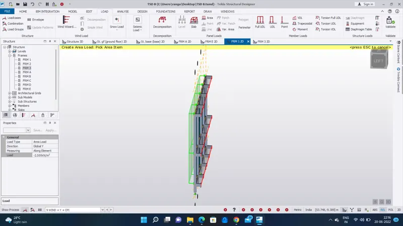
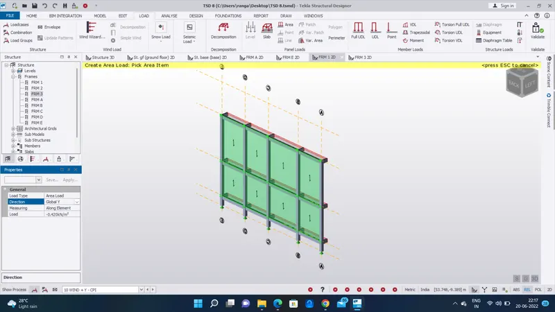
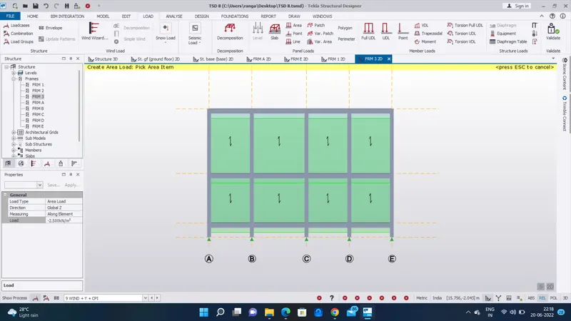
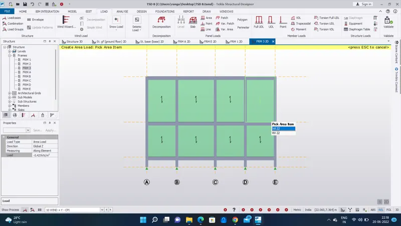
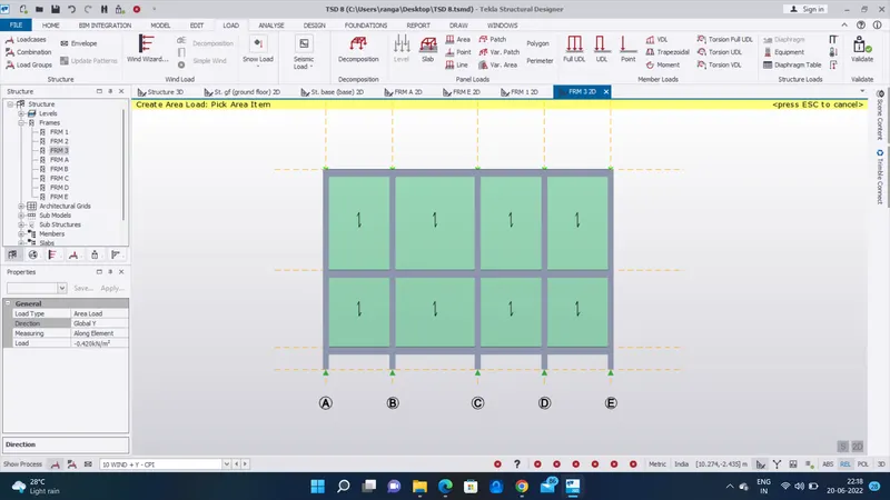
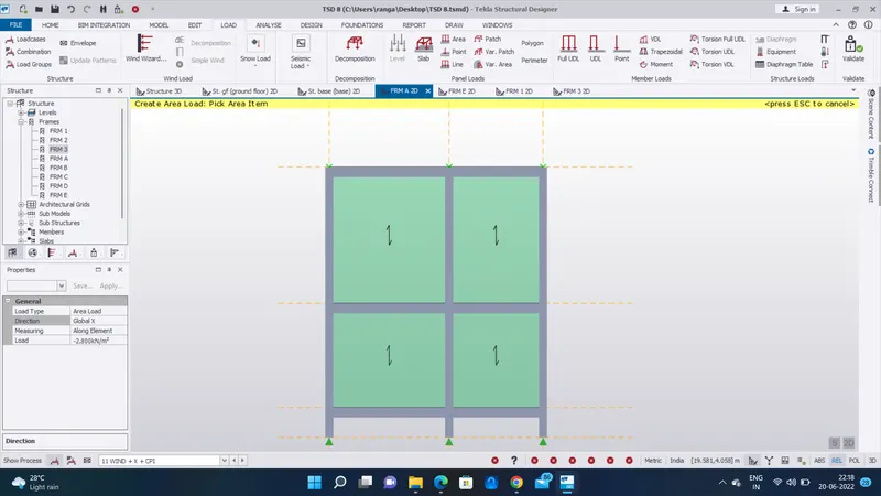
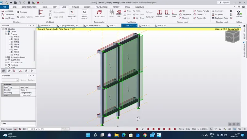
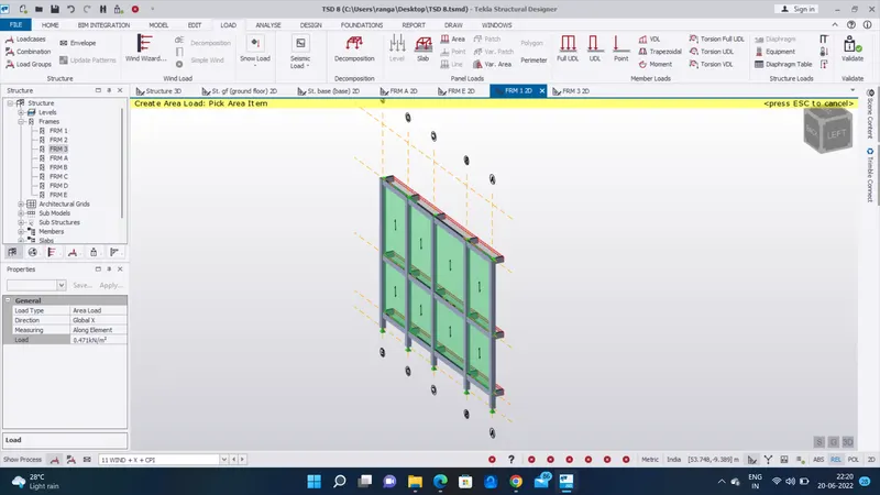
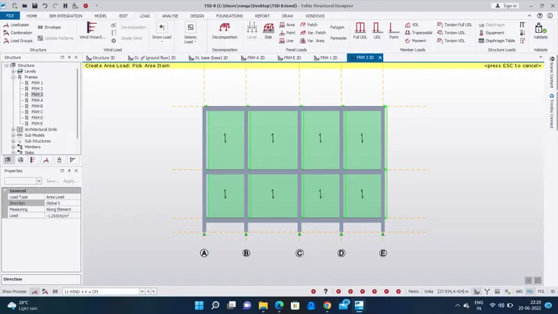
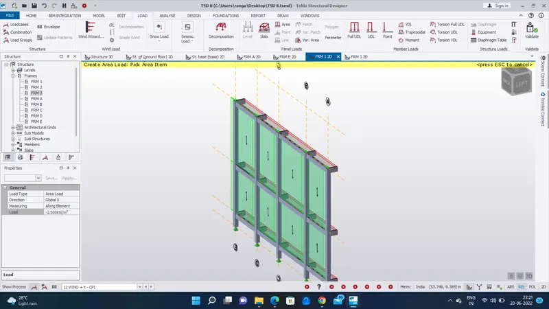
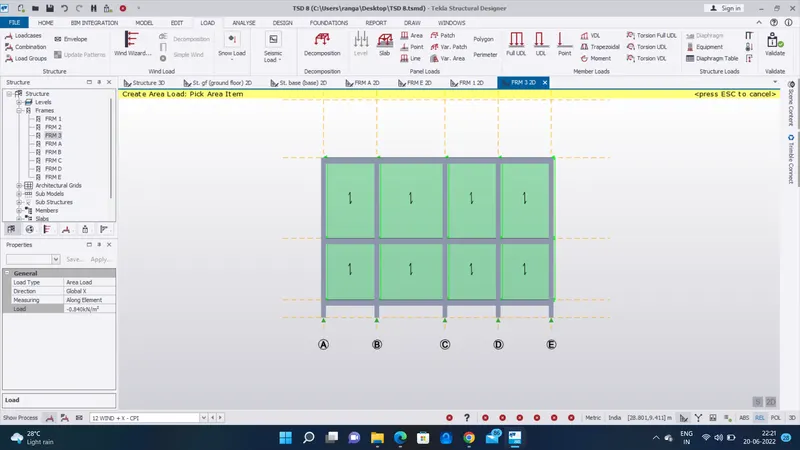
- So Next We Want Apply The Wind Load
- Wind Load Cases As Been Created
- Next Set The Wind Load On Bottom Of The Screen
- And Go To The Area Load
- Set The Global y On The General Box
- Then Apply The Load On The Wall Panel
- Use The Above Calculation To Apply The Load
- Use The Frame Option Select The Frame 1 And 3 , Frame A And E
- Then Use The x And y Direction
- Select And Use The (Wind + Y + CPI), (Wind + y - CPI), (Wind + X + CPI), (Wind + X - CPI),
- Apply All Direction Of The Load As Been Shown Below
RESULT :
As Per The Question The Above Calculation Apply The Loadings On The Model Is Doned