Surface Preparation and Boundary Flagging (No- Hydro)
Surface Preparation and Boundary Flagging
Aim: To perform Surface Preparation and Boundary Flagging on the IC engine and setting up No-Hydro simulation.
Objective:
- To perform surface preparation and flag the boundaries on a given IC engine case.
- Setting up No-Hydro simulation for the above setup.
- To show the mesh on different slices at different time step
- To show the animation how all the valves and pistons move according to crank angles.
Description:
Port Fuel Injection is when fuel is injected prior to the valve and the cylinder, where the combustion happens. The intake valve will have a fuel injection sysem that sprays fuel into the air coming into the engine. From there spark plugs ignite the pressurized slurry of air and fuel, pushing the cylinder head down and spinning the crankshaft.
Procedure:

Initially import the geometry in Converge.
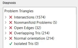
Now check if the complete geometry is imported or not. Once it is successfully done, go to Diagnosis > click on Find to diagnosis the geometry and it will display the 'Problem Triangles' (errors).
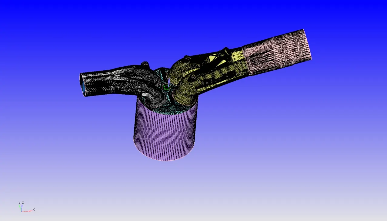
On running the Diagnosis we can see there are many errors in the geometry, which doesnot allow us to run the simulation. To overcome these issue we need to fix these. Before fixing them, we need to flag all the parts in the geometry appropiately. Then once the boundary flagging is done all the errors are visualized and overcomed.
Boundary Flagging:-
To start the process, we need to flag the boundaries and as we flag them we can easly hide the necessary parts easly. This helps us to geometry clean up more effectively. Initially boundary flaging is done for all the parts, later once the surface preparation is done then we can readjust the way we have done the boundary flaging.
Inorder to create Boundary flaging, go to Geometry > Boundary > Flag >create required Boundary Definitions.
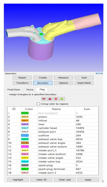
First assign the boundary that doesnot have any problem triangles. As we have various parts in the geometry, Boundary Fence option can be used to seperate the interface between two connected parts. Parts of PFI Engine is described aas follows:
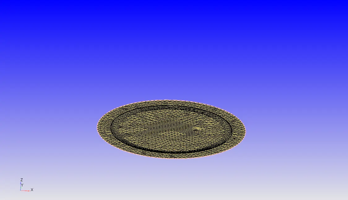
Piston:
A piston is a moving disk enclosed in a cylinder which is made gas-tight by piston rings. The disk moves inside the cylinder as a liquid or gas inside the cylinder expands and contracts. A piston aids in the transformation of heat energy into mechanical work and vise versa too. A piston acts as a movable end of the combustion chamber. Pistons are commonly made of Aluminium alloy for good and lightweight thermal conductivity. Thermal conductivity is the ability of a material to conduct and transfer heat.
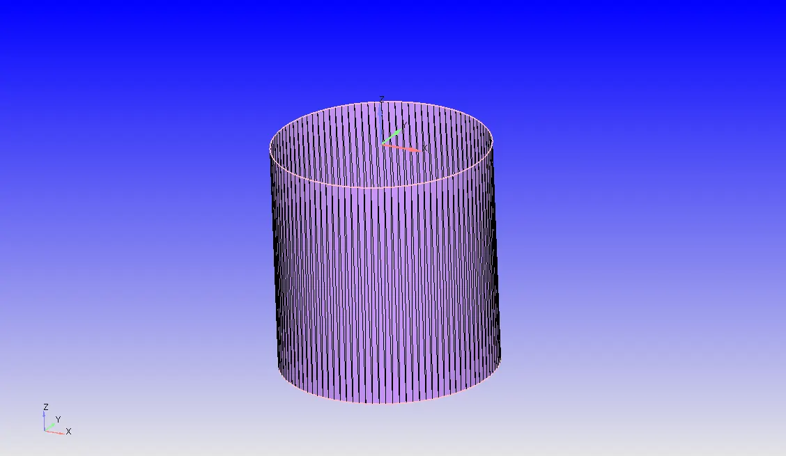
Liner:
A cylinder liner is a cylindrical part that is fitted into an engine block. It is one of the most important functional parts to make up the interior of an engine. Also called as Cylindrical sleeve. THese liners serves as the inner wall of the cylinder and acts as a sliding surface for the piston rings while retaining the lubricant within. The cylinder liners receives combustion heat through the piston and piston rings and transmits the heat to the coolant. These liners prevent the compressed gas and combustion gas from escaping outside. It is necessary that a cylinder liner which is hard to transform by high pressure and temperature in the cylinder.
Cylinder Head:
A cylinder head is usually located on the top of the engine block. It serves as a housing for components such as intake and exhaust valves, combustion chambers etc. It closes in the top of the cylinder, forming the combustion chamber. This joint is sealed by a head gasket.In most of the engines, the head provides space for the passangers that feed air and fuel to the cylinder and that allow the exhaust to escape. The head can also be a place to mount the valves, spark plug and fuel injectors.
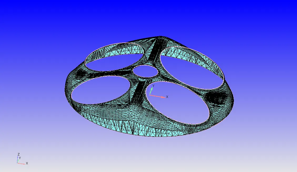
Exhaust Port:
The passage in the cylinder head which connects the exhaust valve and the exhaust manifold. The exhaust gases pass through the port to the exhaust manifold or header.
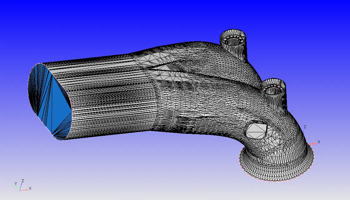
Intake Port:
The passage in the cylinder head which connects the intake manifold to the intake valve through which the air-fuel mixture proceeds on its way to the cylinders.
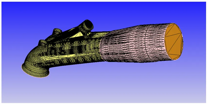
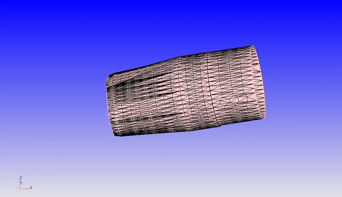
In this case, for baundary flaging we havedivided into various parts i.e.
Intake port-1
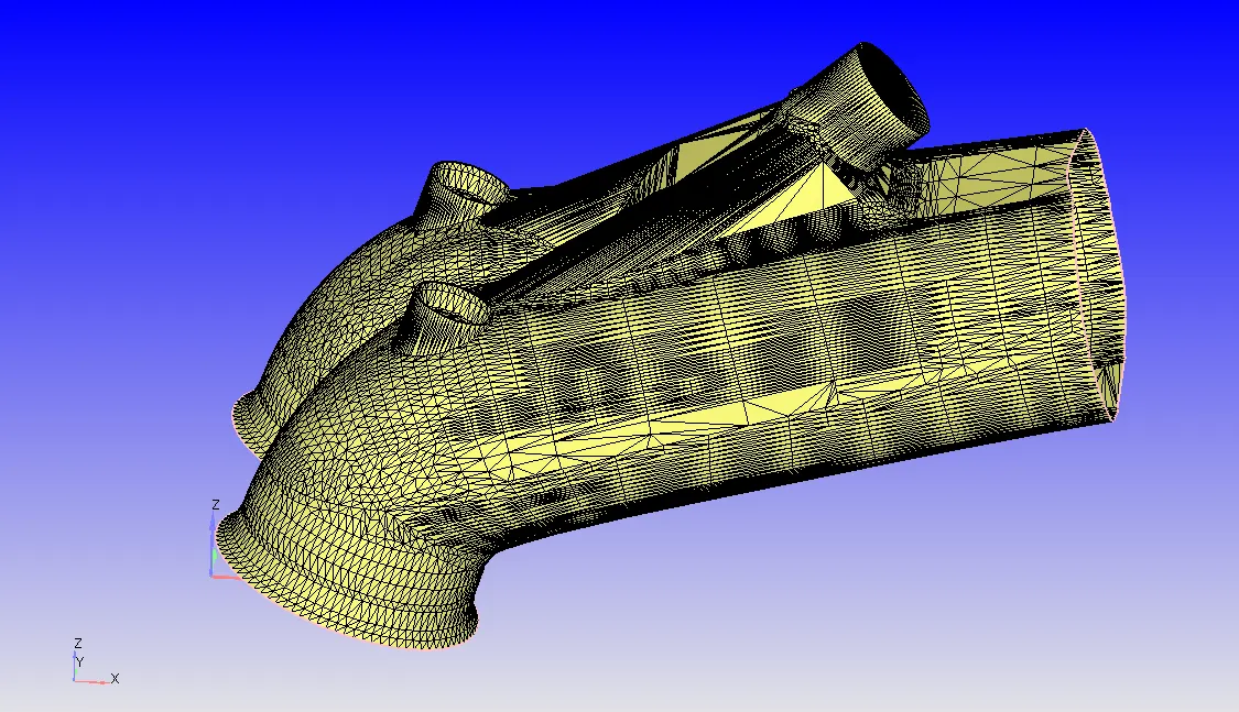
Intake port-2
Intake and Exhaust Valves:
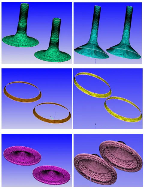
Valves are located in the cylinder head. Main function of the engine valves is to let air in and out of the cylinders. This air is used to help ignite the fuel which will drive the pistons up and down.There aretwo types of engine valves i.e. intake and exhaust valves. The intake valves let the air to flow into the chamber and the exhaust valves let the exhaust air to come out of the chamber. Among commonly used sleeve, sliding, rotary and poppet typevalves, the popet-valve is common as it offers reasonable weight, good strength and good heat transfer characteristics.
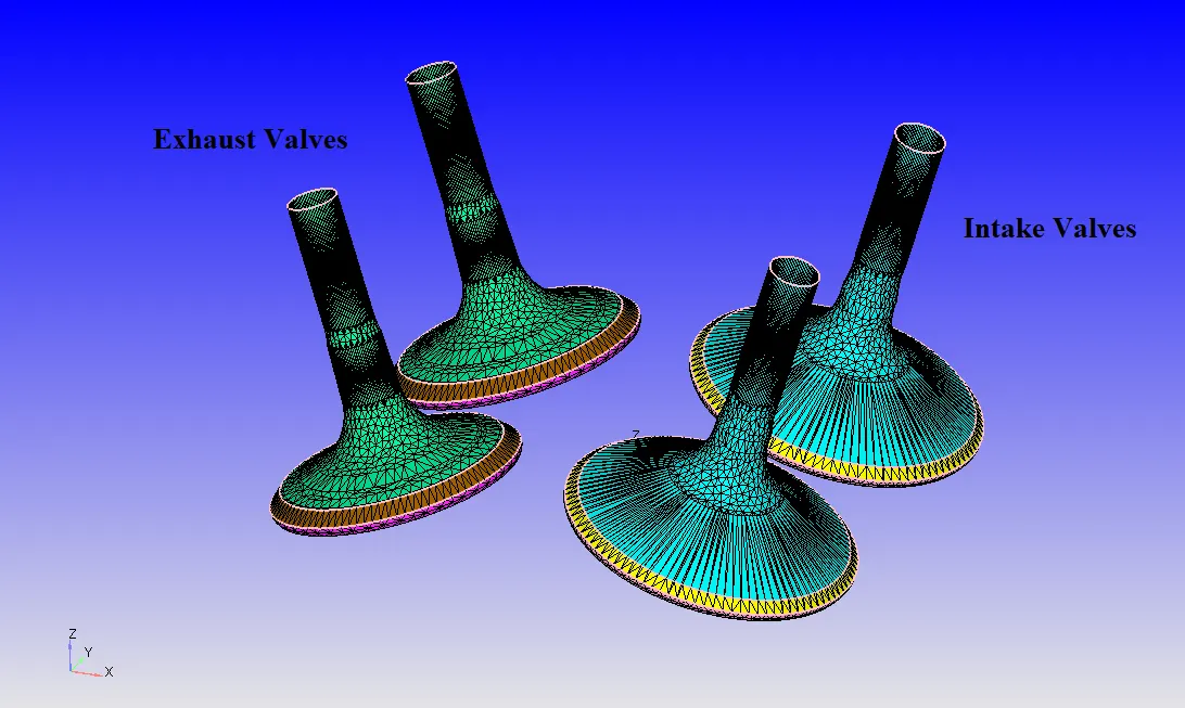
In order to controll the intake and exhaust perfectly, the intake and exhaust valves are flaged with different boundary names. This helps to set valve operation correctly and effectively.
Spark Plug with plug terminal:
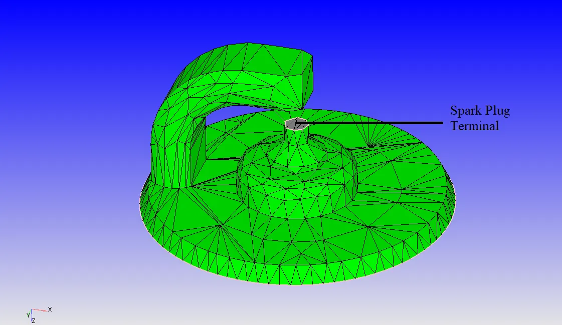
A spark plug is a device that delivers electric current from an ignition system to the combustion chamber of a spark ignition engine to ignite the compressed fuel/air mixture by an electric spark. Spark plug consists of a terminal which as a connector to the ignition system.
Surface Preparation:-
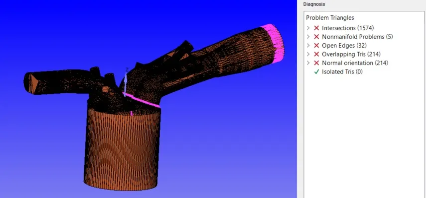
Errors in the Geometry:
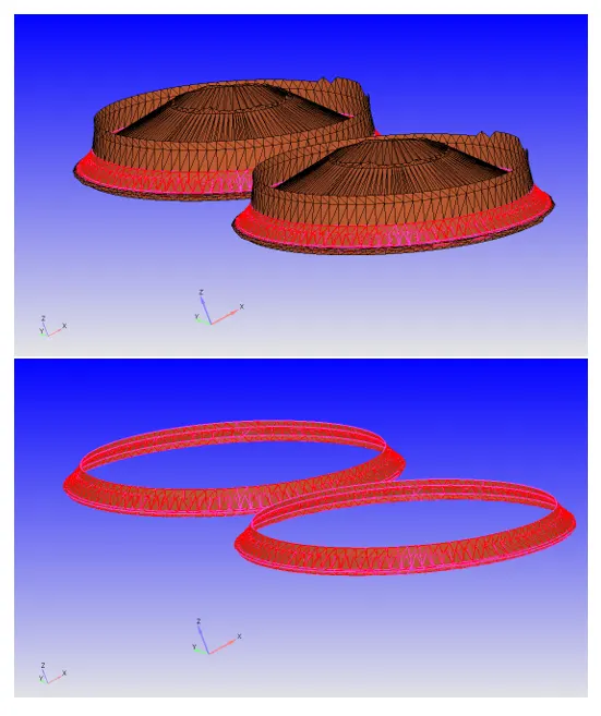
Intersections:
Intersection occurs where there are more than two triangles intersect with each other. Here the intersections between the valves and cylinder head are shown. The slecetion(in red colour) shows how the triangles are intersecting each other which causes the error. Here we can see that the valve angle and the cylinder are crossing each other and hence the where the triangles meet is highlighted.
In order to solve this issue,we need to bring the valve down. This can be obtained by first identifying the ARCnormal at the top valve circle and use translate option and select the boundary (valve top -angle- bottom). It is translated downwards by increasing the value i.e. a particular value should be entered and diagonsis and check if the problem is resolver or not. This verify that there are no intersections. Similarly check if there are any errors.
Nonmanifold Problem:
This problem occurs when there are overlaping triangles. Now stitching the triangles and deleting the duplicate ones will solve this error. Here the edges of the triangles are shared with each other in order to avoid Non manifold errors.
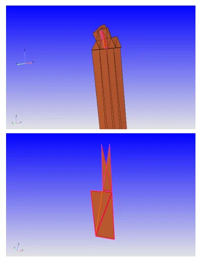
Open Edges:
Open edges are generalformed due to open edges(incomplete triangle formation on the surface). These open edges can be resolved by selecting the Repair >patch > select the open edge>ok. This creates the incomplete triangles to form a complete surface.
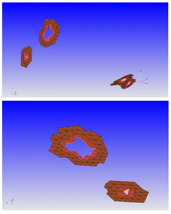
Overlapping Tris and Normal Orientaions:
Overlaping tris are the triangles that are overlaped on each other.Usually these are fixed by deleting the overlapped triangles and patching them back correctly. Here normal orientation is clubbed with the overlapping tris. This can be fixed by checking the direction of normals. If the normals are pointing outwards then just transform them inside.
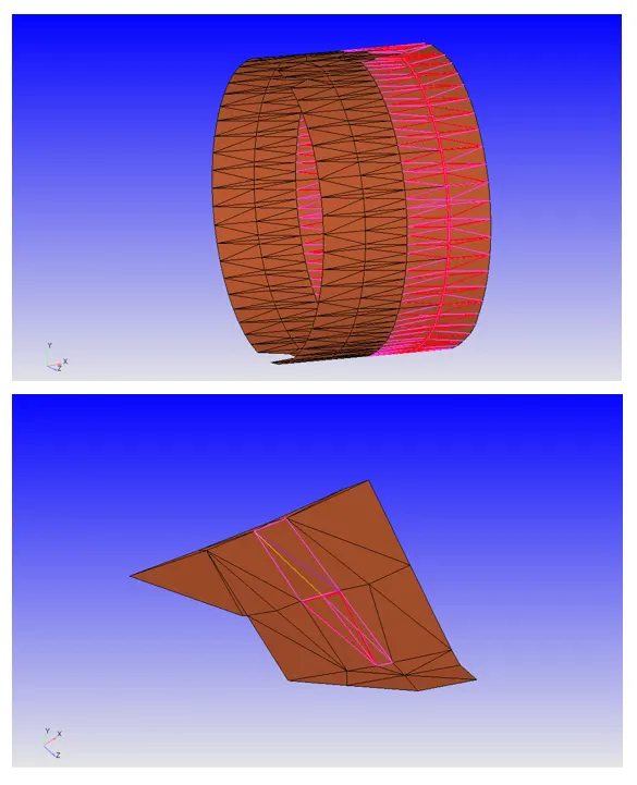
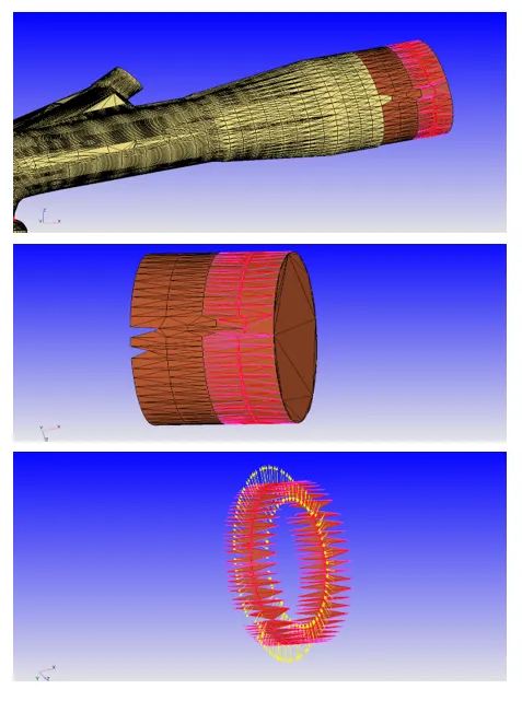
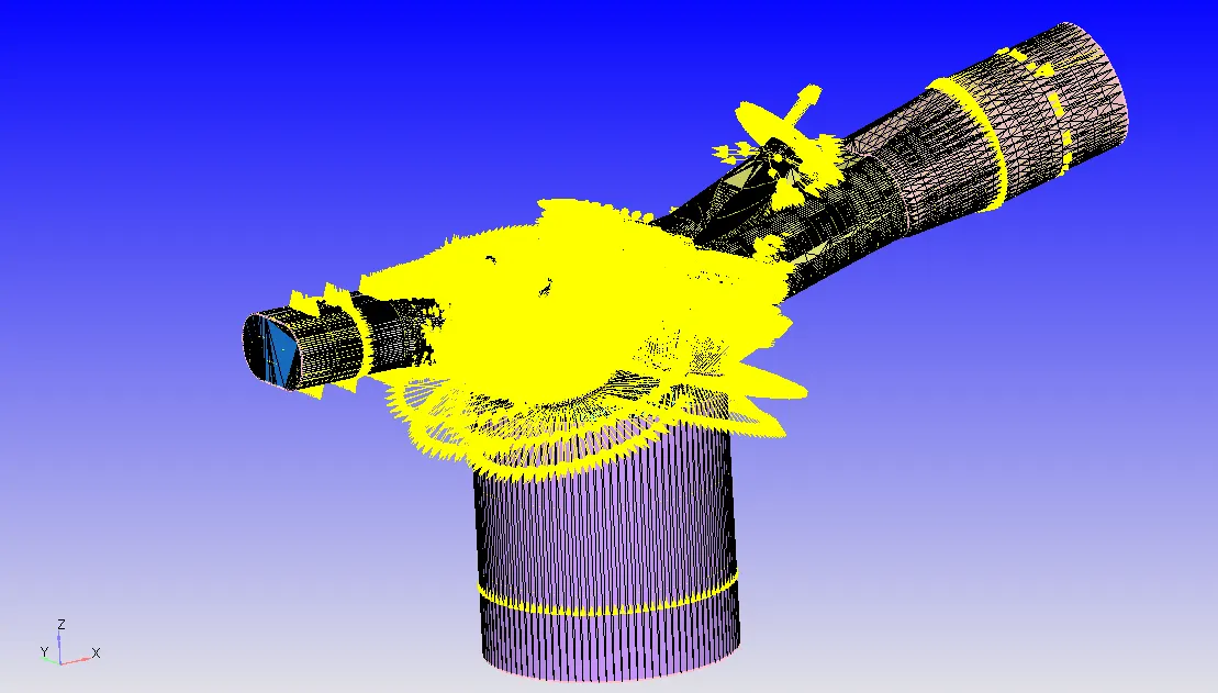
When we try to remove the error at each step we need to Run Diagnosis and check if they are resolved. If all the problems are resolved then it shows the following output when we run the Diagnosis;
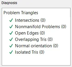
Once this successful we can check all the boundary flagging and start setting up the case. The procedure follows;
Case Setup:
Application Type-
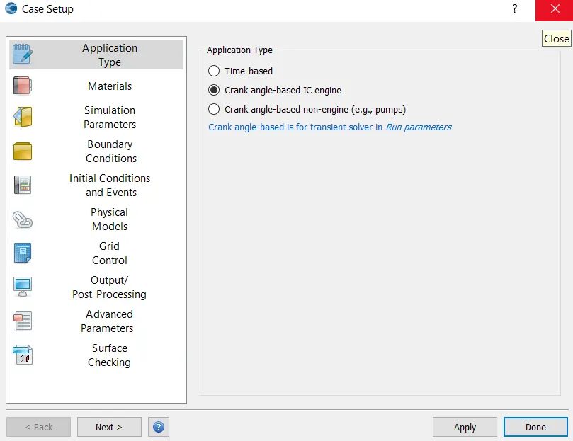
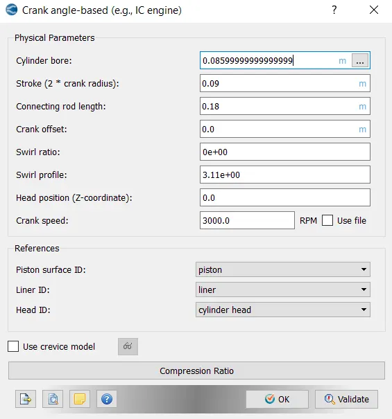
Materials-
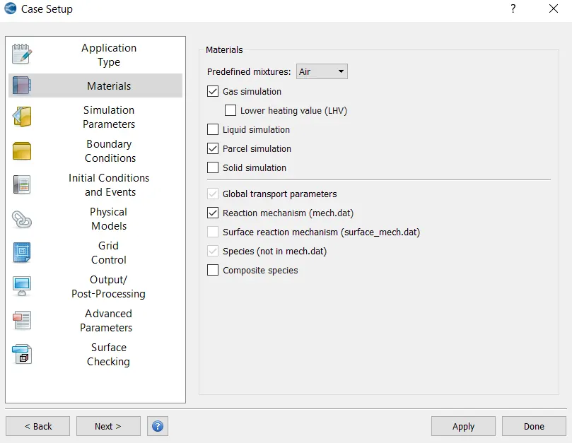
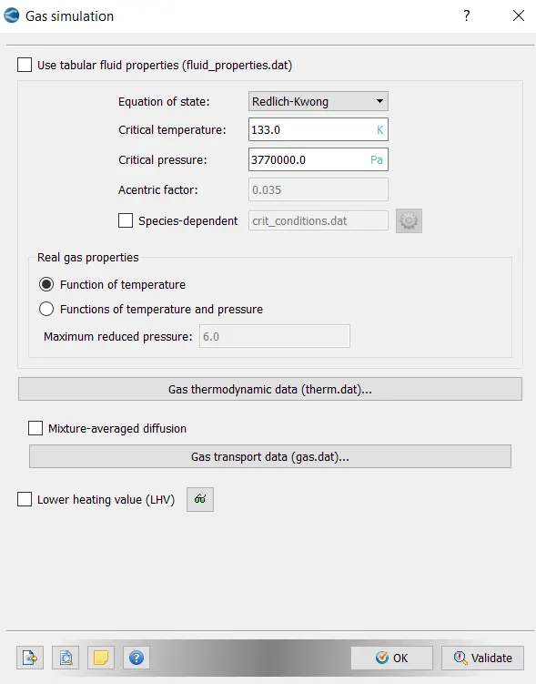
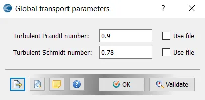
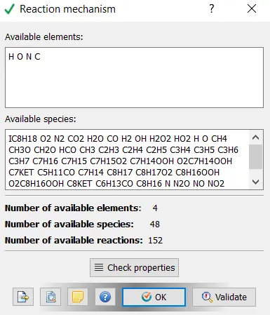
Simulation Parameters-
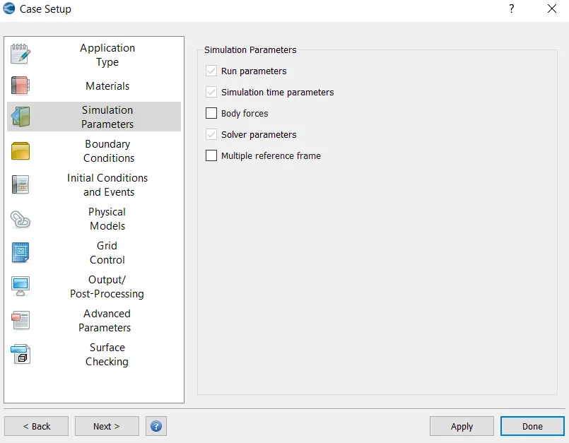
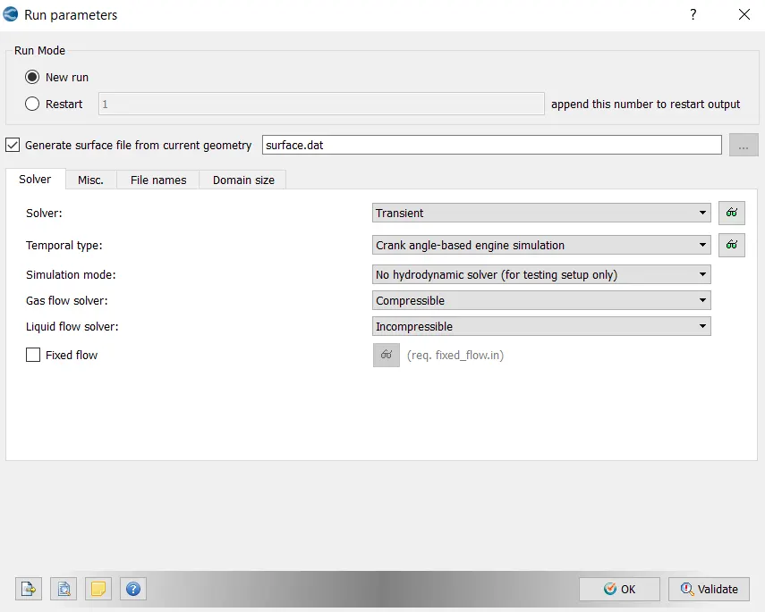
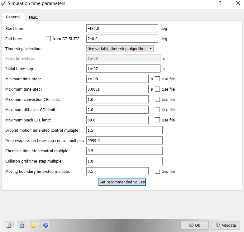
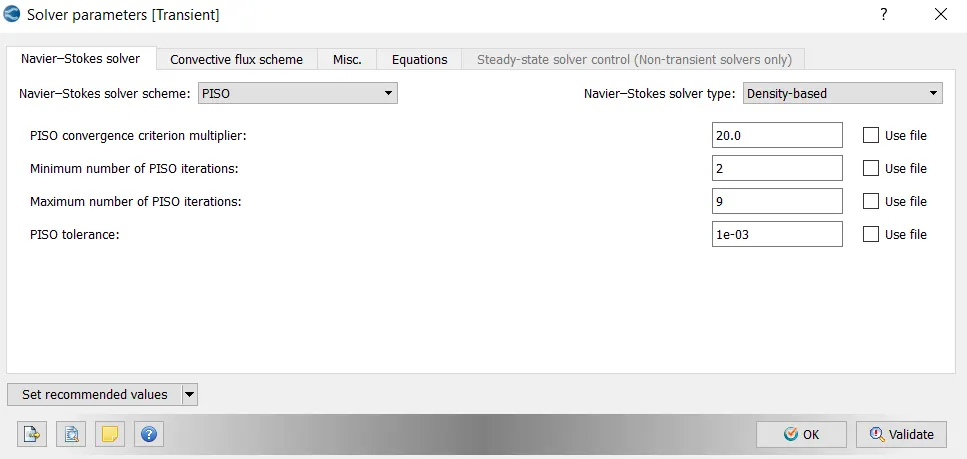
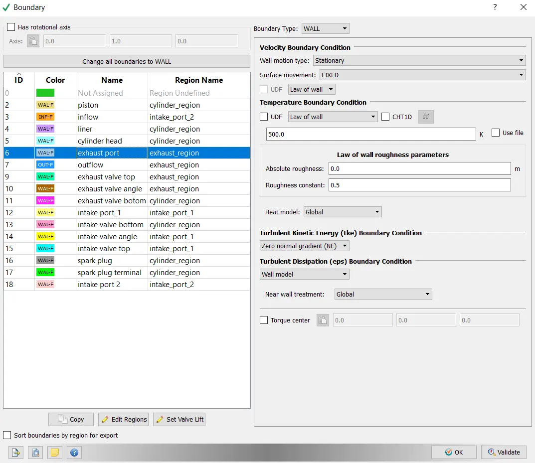
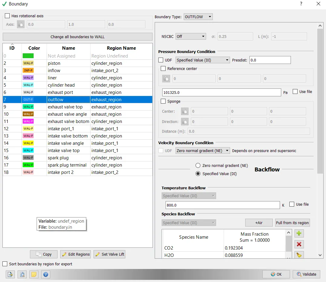
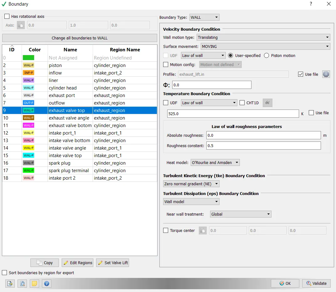
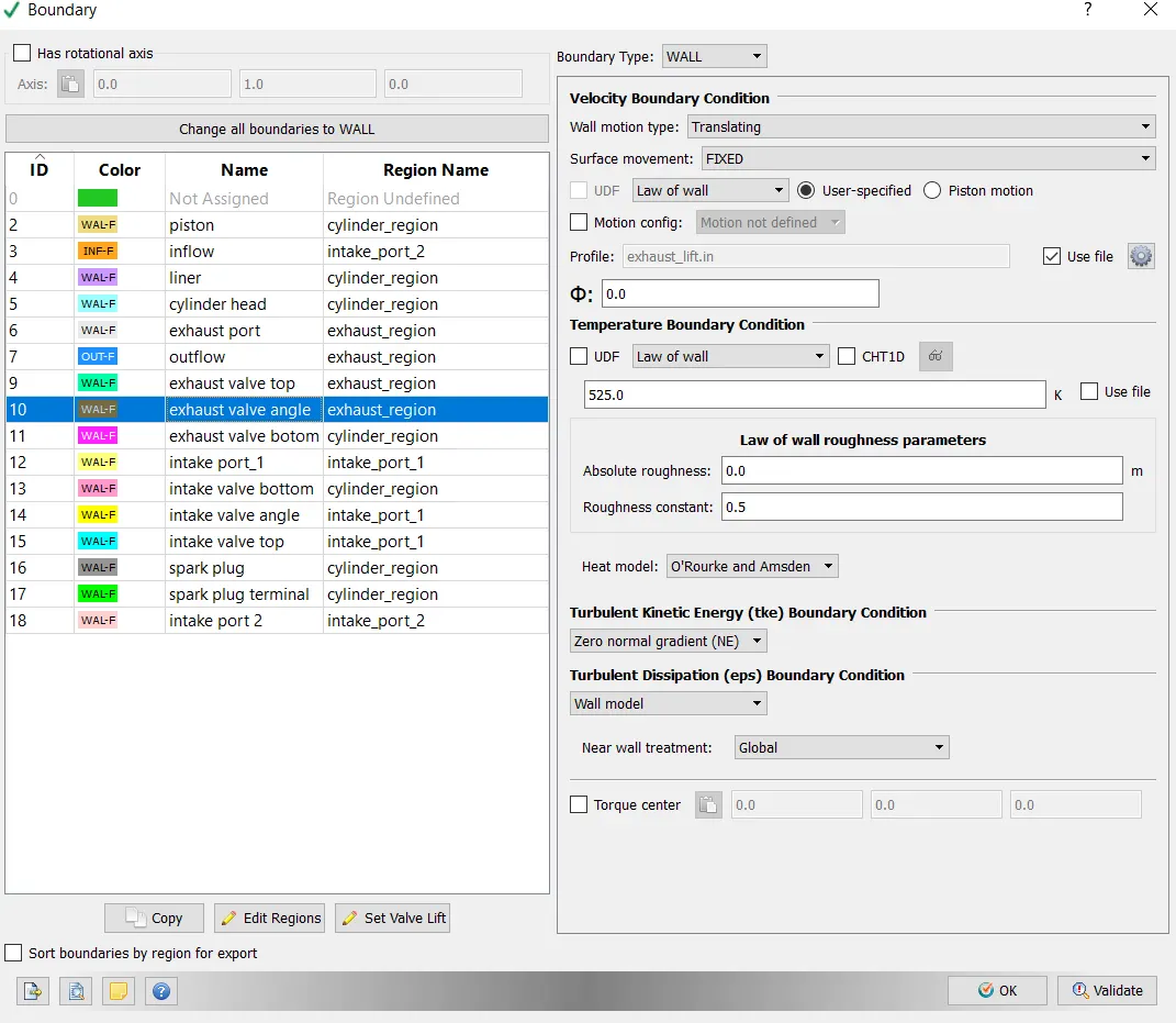
Boundary Conditions-
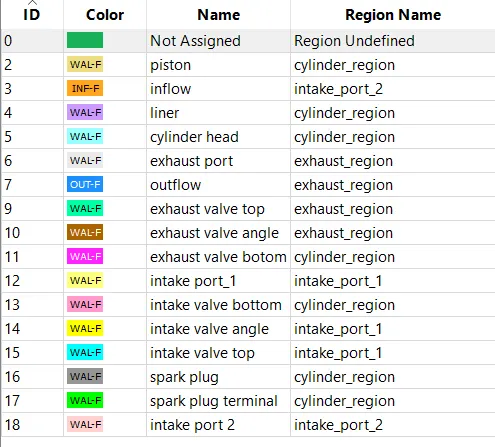
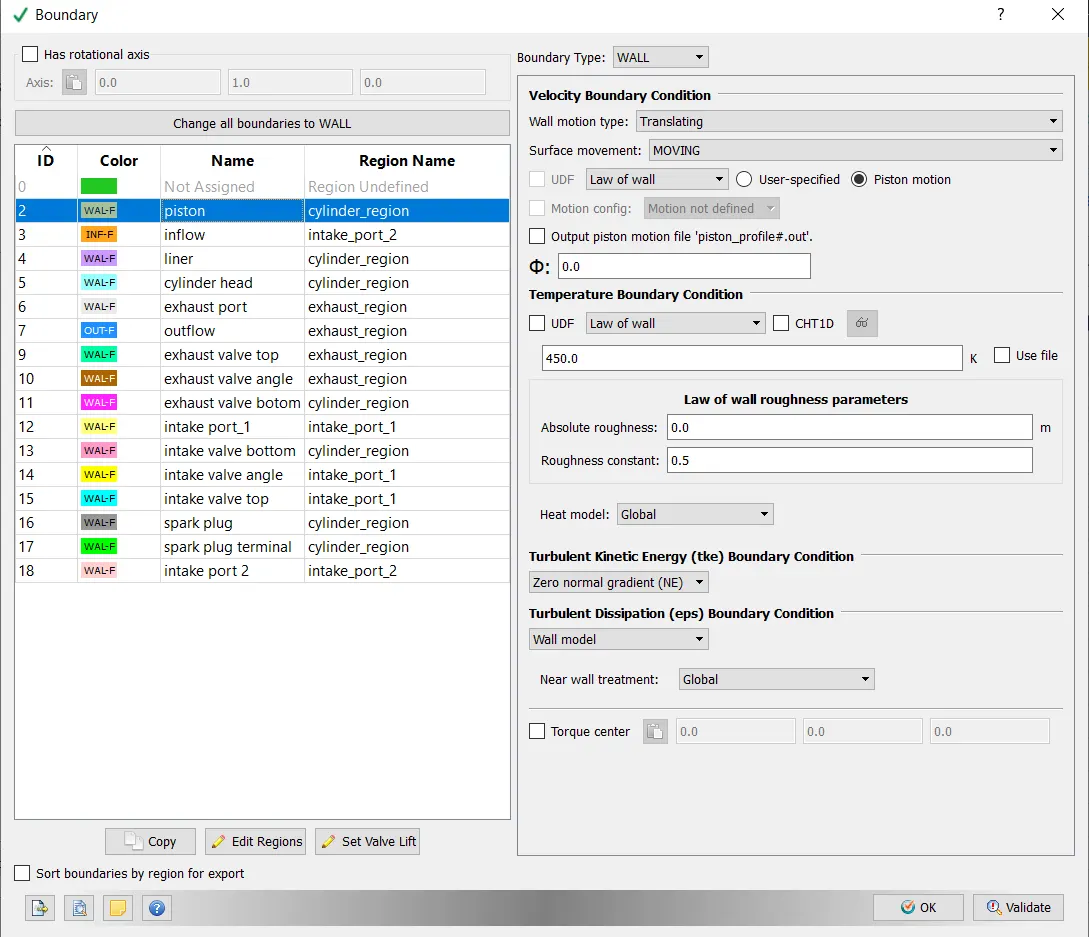
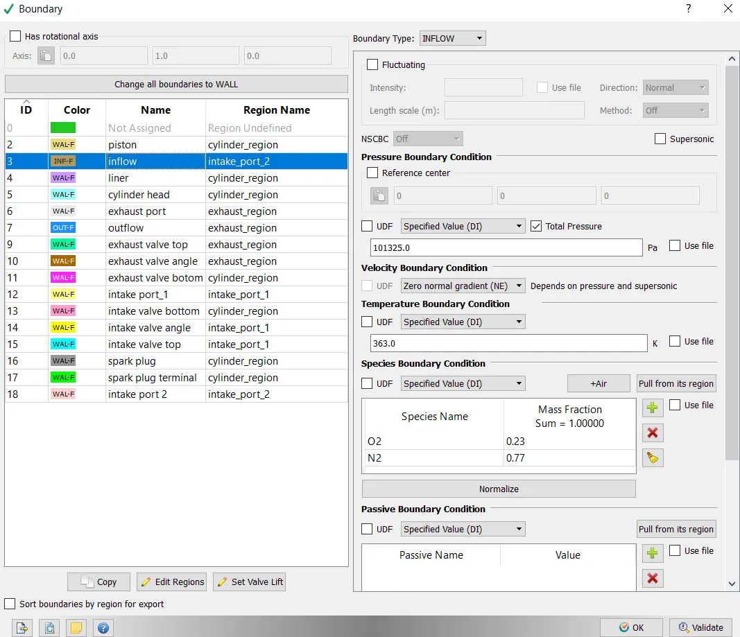
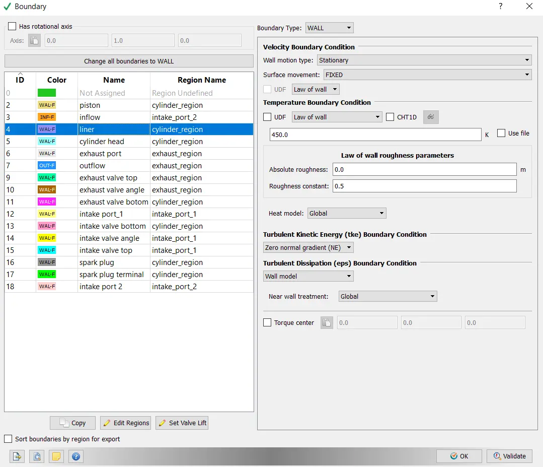
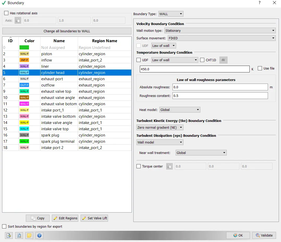
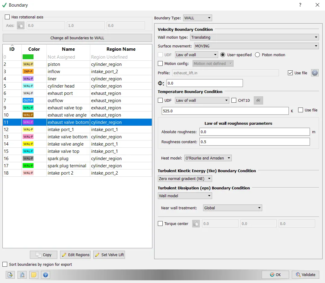
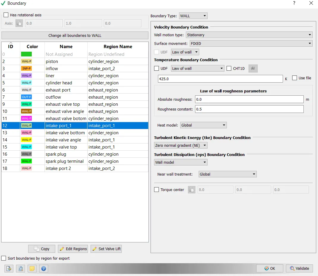
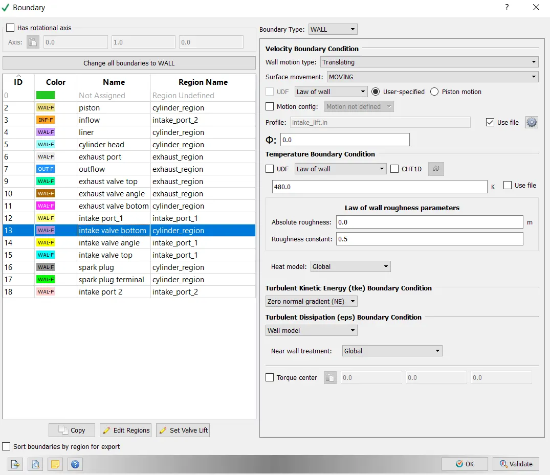
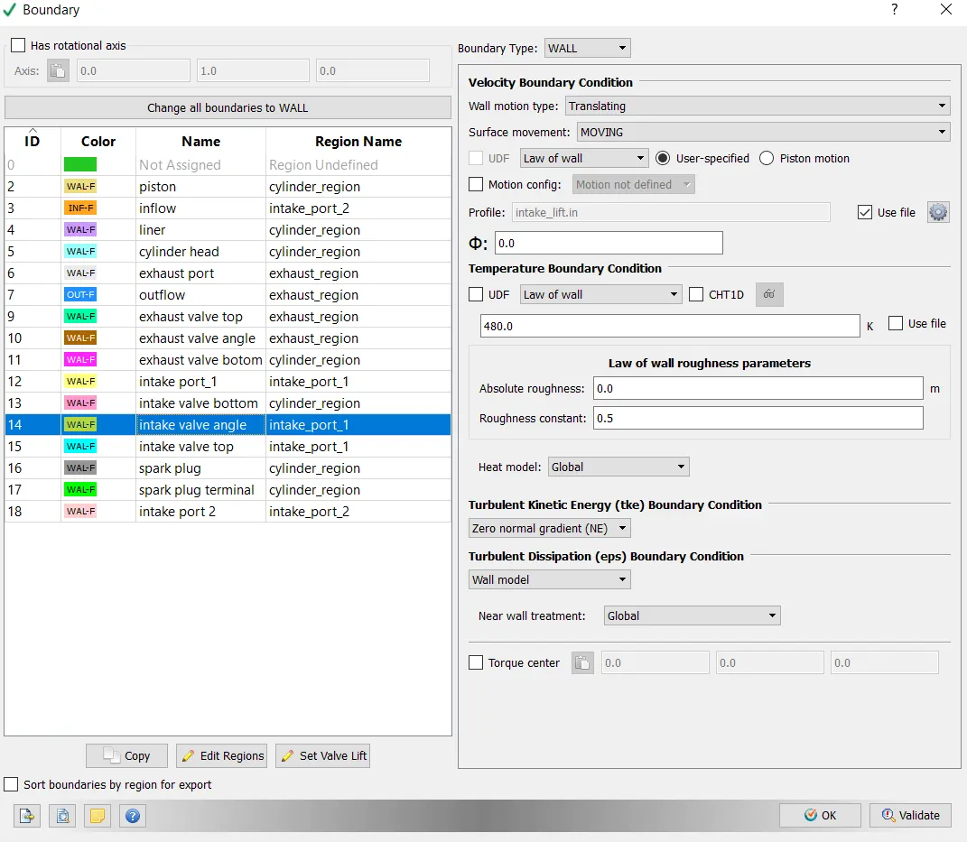
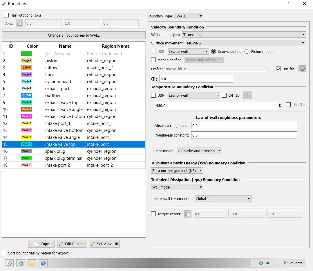
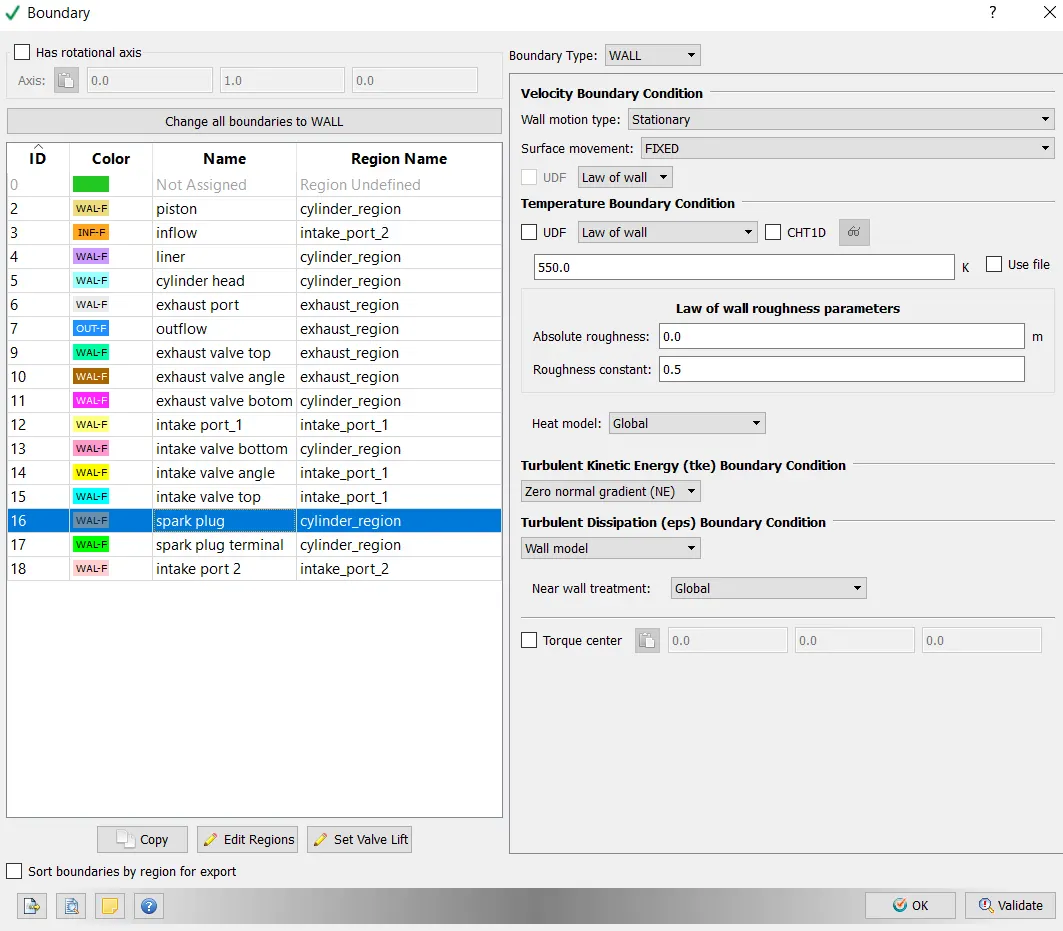
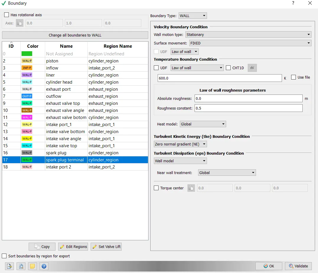
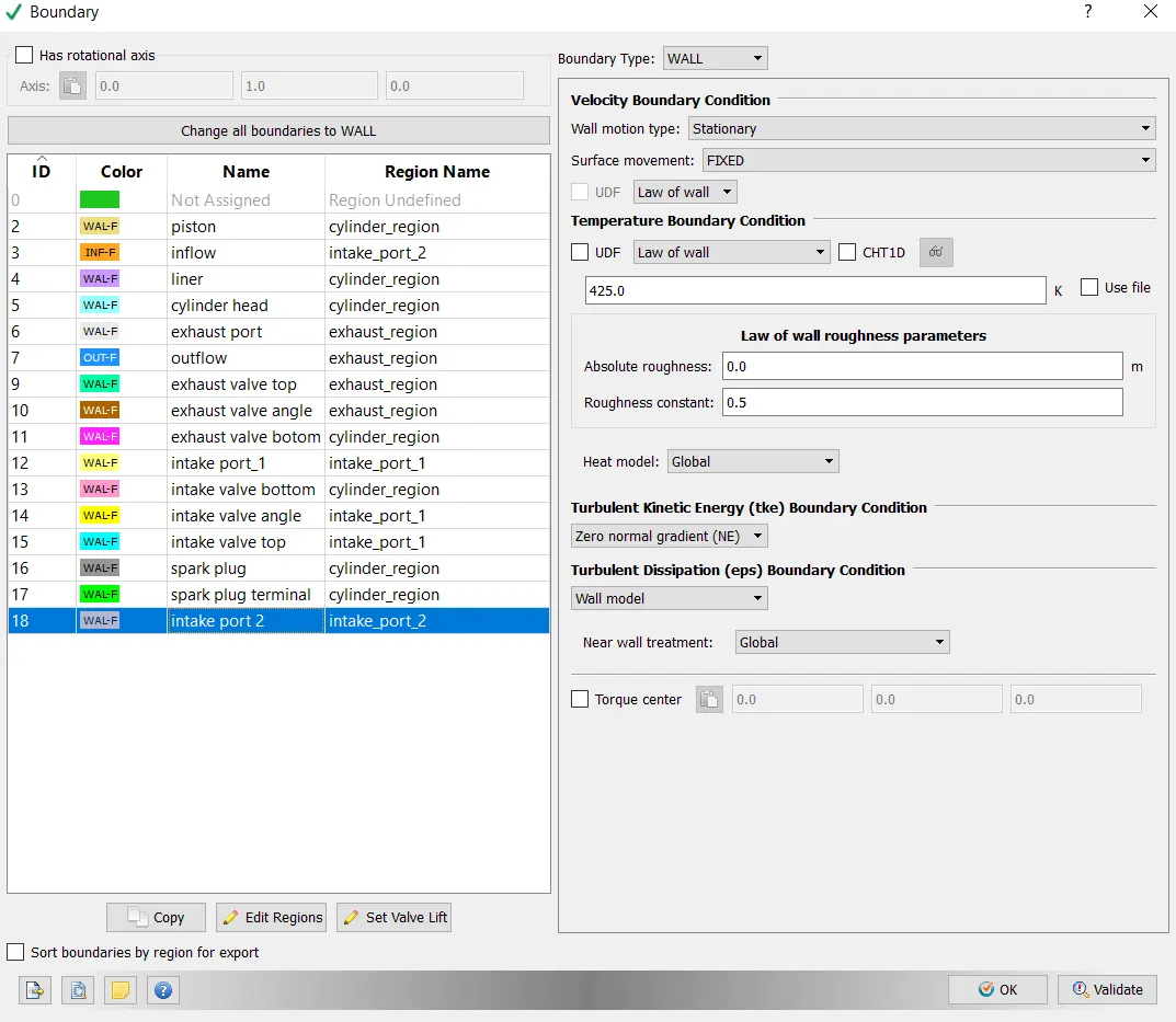
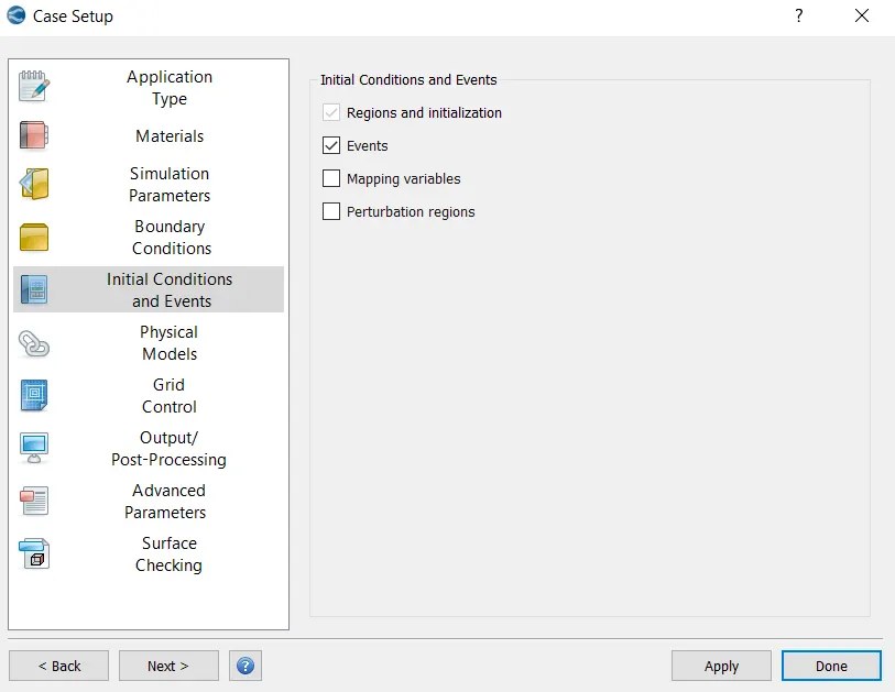
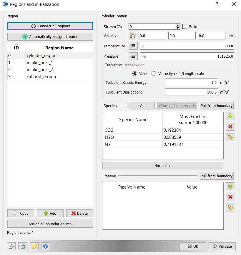
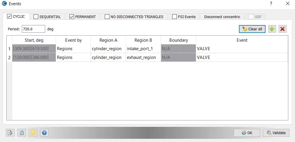
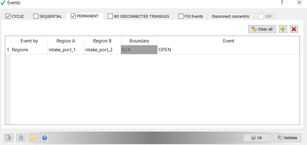
Initial Conditions and Events-
Physical Modes-
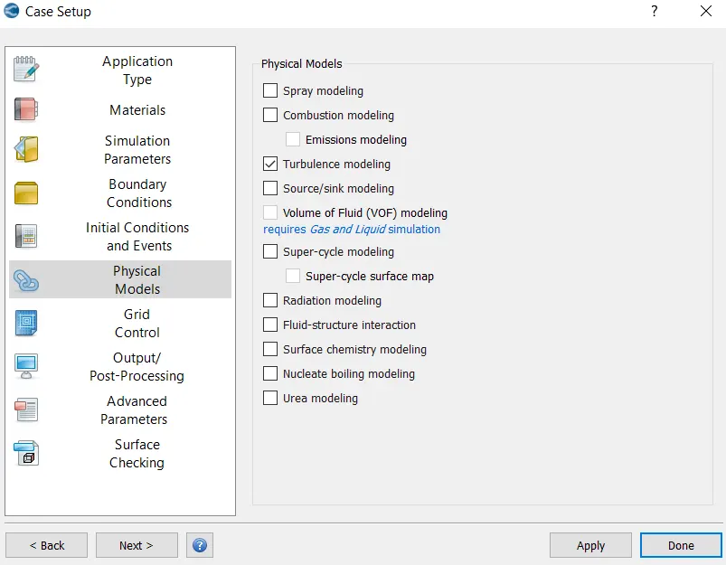
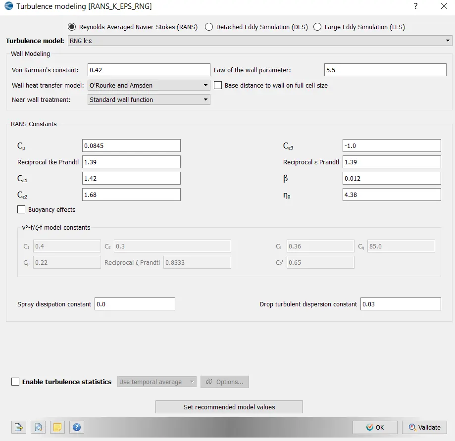
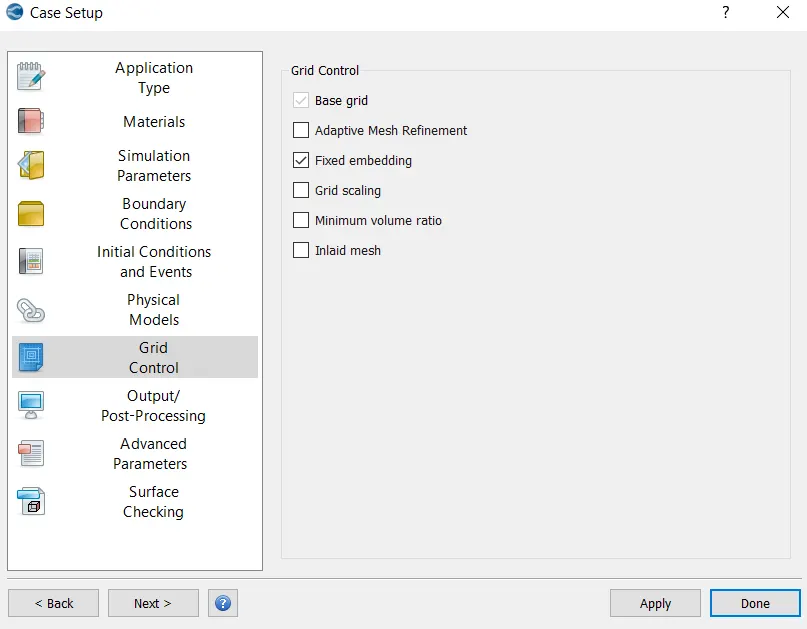
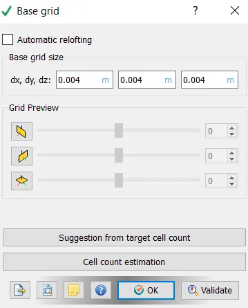
Grid Control-
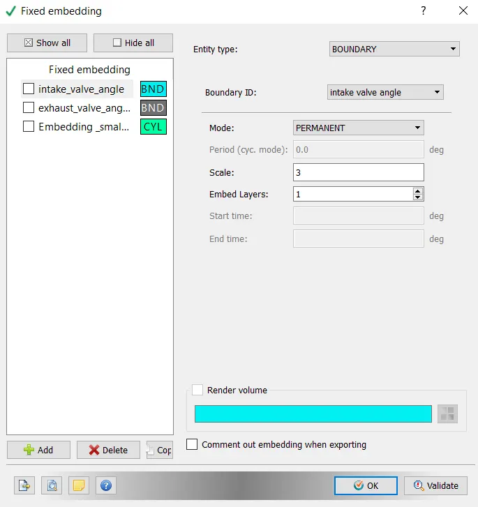
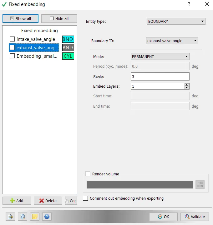
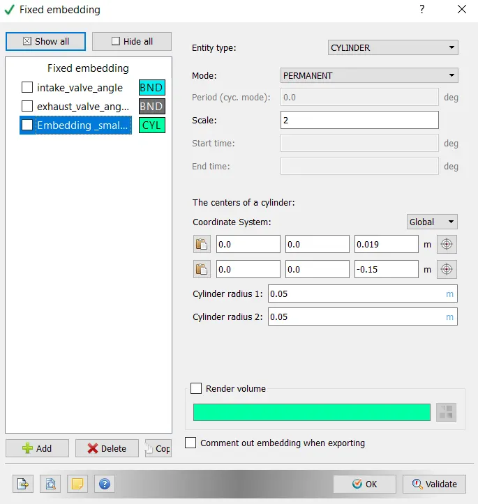
Output/Post-Processing-
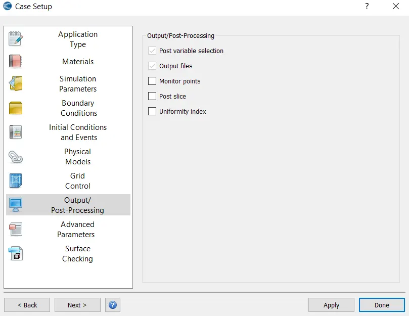
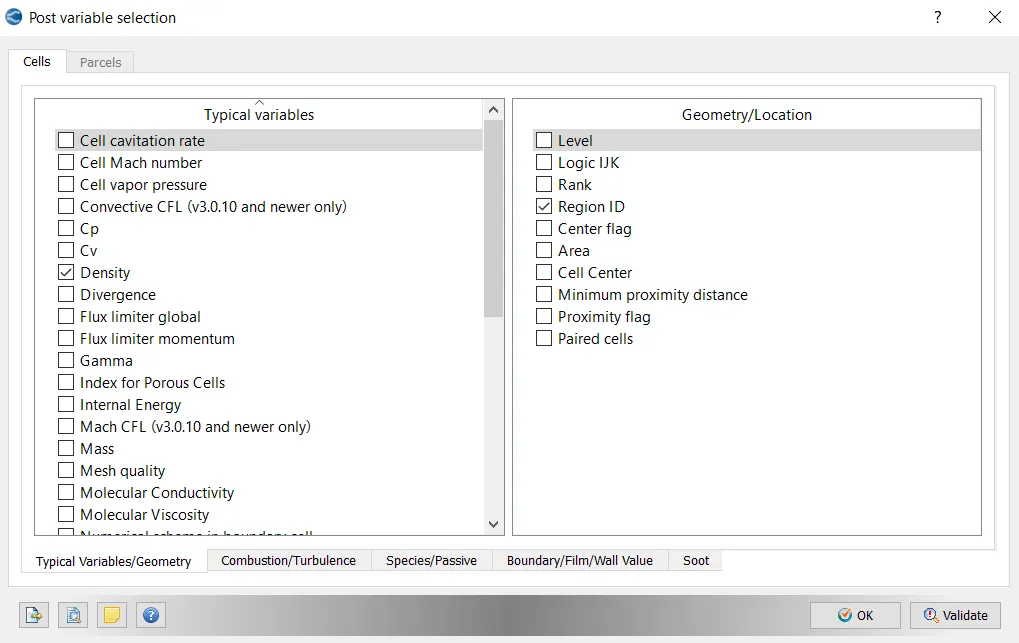
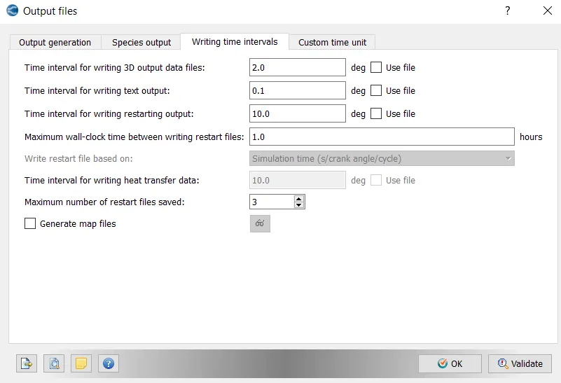
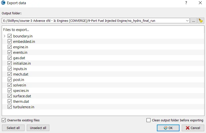
With this setting up of the case is complete and now go to Files > Export > click on Export Input Files. Select the destination folder (test) to save the data.
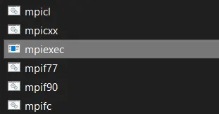
After importing the input files,paste the "mpiexec.exe" file.
Now, open Cygwin and navigate to the location where the setup files are imported.
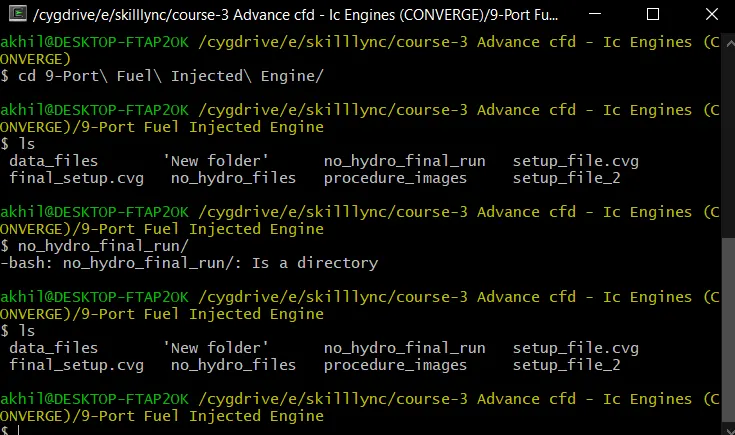
Once we navigate to the respective folder, we need to run the simulation. To run the simulation, use the following command in Cygwin;

Here path is copied from " C:ProgramFilesConvergent_ScienceCONVERGE3.0.15binconverge-intelmpi.exe ".
Now the simulation starts running, and it displays the steps in cygwin. As the simulation begins it creates multiple folders (i.e. '.scratch' & output) in the path where we saved the input files.
Once the simulation is complete, to perform post processing we need to convert the obtained result data into format where we can access in Paraview. These converted files are directed to the Output folder.
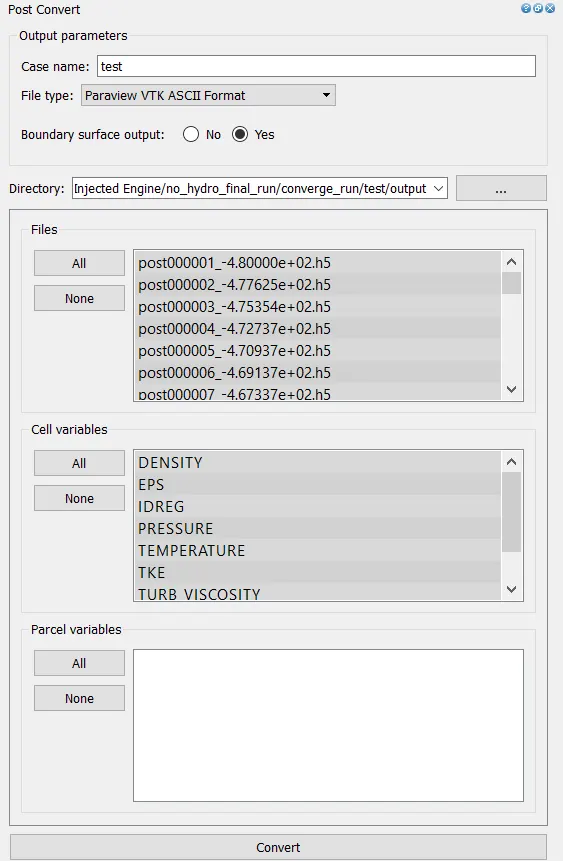
Open PARAVIEW > direct to folder where the output is saved > select '.vtm(group file)' > data imported to paraview.
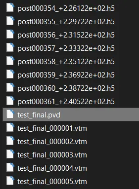
Animation showinhg all the valves and piston moving according to the crank angles is generated and later it is inspected if the piston, valves are operating as per the values provided.
Result:
Animation (Case-No-Hydro):
Conclusion:
Hence boundary flagging for all the components in the geometry and then surface preparation i.e. fixing of Problem Triangles(errors) found during diagnosis. The animation showing how piston, valves move according to the cranck angles is clearly shown.