Studying Induction Motor characteristics using MATLAB
1.Discuss about the equivalent circuit network of induction motor MATLAB model.
One way to analyse and understand the operation of an induction motor is by the use of an equivalent circuit.
But first we to need understand about few parameters
Slip
Induction motors are asynchronous. The stator magnetic field rotates at the motors synchronous speed (ns). The rotor can never rotate at synchronous speed, otherwise there would be no induced current.
The difference between the motors synchronous speed(`n_s`) and actual asynchronous speed(`n_r`) is known as the slip.
therefore, Slip `S=(n_s-n_r)/n_s`
Frequency
From magnetic winding theory, the relationship between frequency in the stator (f), number of pole pairs (p) and the synchronous speed is given by
`f=n_sp`
Euqivalent Induction Motor Circuit
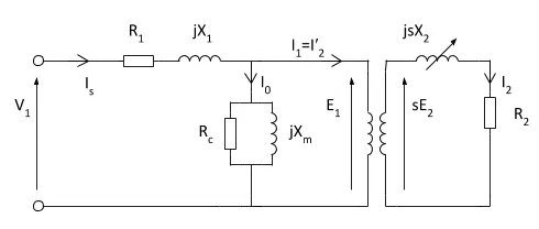
-
R1 is the stator resistance.
-
R2 is the rotor resistance with respect to the stator.
-
L1 is the stator inductance.
-
L2 is the rotor inductance with respect to the stator.
-
Lm is magnetizing inductance.
- s is the rotor slip.
In the equivalent circuit R1 represents, the resistance of the stator winding and X1 the stator leakage reactance (flux that does not link with the air gap and rotor). Magnetising reactance required to cross the air gap is represented by Xm and core losses (hysteresis and eddy current) by Rc.
An ideal transformer of N1 and N2 turns respectively represents the air gap. For the rotor side, the induced emf is affected by the slip (as the rotor gains speed, slip reduces and less emf is induced). The rotor resistance and reactance are represented by R2 and X2; with X2 being dependant on the frequency of the inductor rotor emfs.
The rotor circuit, the current I2 is given by:
`I_2=(sE_2)/sqrt((R_2)^2+(sX_2)^2`
`I_2=(E_2)/sqrt((R_2/s)^2+(X_2)^2`
this circuit can be further simplified and represented as
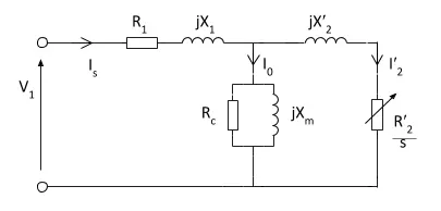
The reffered values are calculated by multiplying them by `k^2`, where k is the effective stator/rotor turns ratio.
Torque equation
`T=3/(omega_(ms))[(V^2((R_2)/S))/((R_1+R_2/S)^2+(X_1+X_2)^2]]`
________________________________________________________________________________________________________________________
2. 3 phase, 50 Hz induction motor, represented by equivalent circuit constants X1 = X2 = 0.1 ohm and R1 = R2 = 0.2 ohm is operated at half of rated voltage and frequency. Calculate the ratio of starting torque at half voltage & frequency to rated values.
Given
Frequency - 50 Hz
Stator inductance X1 = 0.1
Rotor inductance X2 = 0.1
Stator resistance R1 = 0.2 ohm
Rotor resistance R2 = 0.2 ohm
No of phases - 3
Torque `T=3/(omega_(ms))[(V^2((R_2)/S))/((R_1+R_2/S)^2+(X_1+X_2)^2]]`
now,
Rated frequency `f` = 50Hz
Rated synchronous speed
`omega_(m)^' = (120*f)/p`
`omega_(m)^' = (120*50)/p`
`omega_(m)^' = (6000)/p`
Half rated frequency `f^'` = 25Hz
Half rated synchronous speed
`omega_(ms)^' = (120*f^')/p`
`omega_(ms)^' = (120*25)/p`
`omega_(ms)^' = (3000)/p`
Rated torque
`T=3/(omega_(ms))[(V^2(R_2))/((R_1+R_2)^2+(X_1+X_2)^2]]`
`T=3/(omega_(ms))[(V^2(0.2))/((0.2+0.2)^2+(0.1+0.1)^2]]`
`T=(3*V^2)/(omega_(ms))`
Half rated torque
`T^'=1/2*3/(omega_(ms))[(V^2(R_2))/((R_1+R_2)^2+(X_1+X_2)^2]]`
`T^'=1/2*3/(omega_(ms))[(V^2*0.2)/((0.2+0.2)^2+(0.1+0.1)^2]]`
`T^'=(1.5*V^2)/(omega_(ms))`
Now, to find ratio
`T^'/T=((1.5*V^2)/(omega_(ms)))/((3*V^2)/(omega_(ms)))`
`T^'/T=1/2=0.5`
ratio of starting torque at half voltage & frequency to rated values is 0.5
________________________________________________________________________________________________________________________
3. Make a MATLAB script file which will plot speed torque characteristics for frequency control method.
clear all
close all
clc

% Data inputs
p = 4; % No of poles
s=linspace(0,1,100); % slip
R1 = 0.2; % stator resistance
R2 = 0.2; % rotor resistance
X1 = 0.1; % stator inductance
X2 = 0.1; % rotor inductance
V = 400/sqrt(3); % voltage per phase
f = linspace(0.5,2,5); % frequency

for i=1:5
    % synchronous speed rad/sec
    wms = (120*f(i))/p;
    for j=1:100
        % torque N-m
        wm(j)=(1-s(j)).*(wms);
        d=((R1+((R2)./(s(j)))).^2)+((X1+X2)^2);
        T(j)=((3/wms)*((V^2)*(R2)./s(j)./(d)));
    end

    %plotting
    plot(wm, T,'linewidth',2)
    hold on
    title('Motor speed vs Torque')
    xlabel('Speed in rad/sec')
    ylabel('Torque in N-m')
    grid on
end
Output
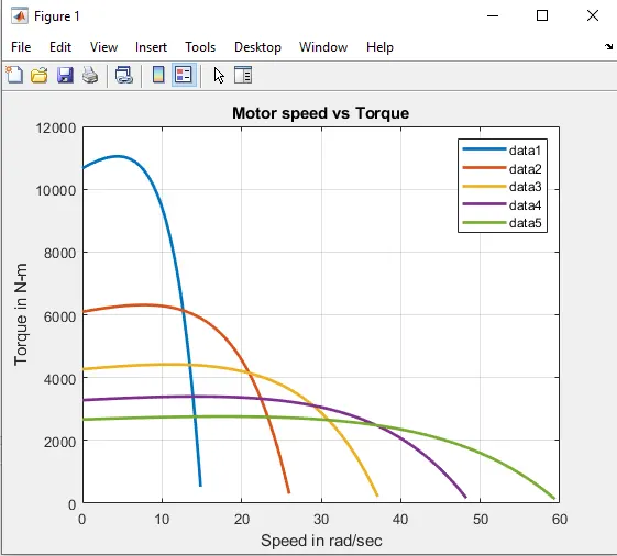
By seeing the graph we can observe that with increasing frequency the speed of the motor also increases.
But torque reduces with increasing speed.
________________________________________________________________________________________________________________________
4. Explain in brief about operation of BLDC motor.
Brushless DC motors
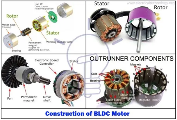
A brushless DC motor consists of a rotor in the form of a permanent magnet and stator in the form of polyphase armature windings. It differs from the conventional dc motor in such that it doesn’t contain brushes and the commutation is done using electrically, using an electronic drive to feed the stator windings.
Basically a BLDC motor can be constructed in two ways- by placing the rotor outside the core and the windings in the core and another by placing the windings outside the core. In the former arrangement, the rotor magnets act as an insulator and reduce the rate of heat dissipation from the motor and operate at low current. It is typically used in fans. In the latter arrangement, the motor dissipates more heat, thus causing an increase in its torque. It is used in hard disk drives.
4 Pole 2 Phase motoroperation
Working principle
The principles for the working of BLDC motors are the same as for a brushed DC motor, i.e., the internal shaft position feedback. In the case of a brushed DC motor, feedback is implemented using a mechanical commutator and brushes. Within BLDC motor, it is achieved using multiple feedback sensors. In BLDC motors we mostly use a Hall-effect sensor, whenever rotor magnetic poles pass near the hall sensor, they generate a HIGH or LOW-level signal, which can be used to determine the position of the shaft. If the direction of the magnetic field is reversed, the voltage developed will reverse too.
The brushless DC motor is driven by an electronic drive that switches the supply voltage between the stator windings as the rotor turns. The rotor position is monitored by the transducer (optical or magnetic) which supplies information to the electronic controller and based on this position, the stator winding to be energized is determined. This electronic drive consists of transistors (2 for each phase) which are operated via a microprocessor.
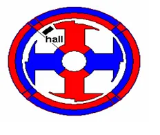
The magnetic field generated by the permanent magnets interacts with the field induced by the current in the stator windings, creating a mechanical torque. The electronic switching circuit or the drive switches the supply current to the stator so as to maintain a constant angle of 0 to 90 degrees between the interacting fields. Hall Sensors are mostly mounted on the stator or on the rotor. When the rotor passes through the hall sensor, based on the North or South Pole, it generates a high or low signal. Based on the combination of these signals, the winding to be energized is defined. In order to keep the motor running, the magnetic field produced by the windings should shift position, as the rotor moves to catch up with the stator field.
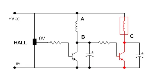
In a 4 pole, 2 phase brushless dc motor, a single hall sensor is used, which is embedded on the stator. As the rotor rotates, the hall sensor senses the position and develops a high or low signal, depending on the pole of the magnet (North or South). The hall sensor is connected via a resistor to the transistors. When a high voltage signal occurs at the output of the sensor, the transistor connected to coil A starts conducting, providing the path for the current to flow and thus energizing coil A. The capacitor starts charging to the full supply voltage. When the hall sensor detects a change in polarity of the rotor, it develops a low voltage signal at its output and since the transistor 1 doesn’t get any supply, it is in cutoff condition. The voltage developed around the capacitor is Vcc, which is the supply voltage to the 2nd transistor, and coil B is now energized, as current passes through it.
BLDC motors have fixed permanent magnets, which rotate and a fixed armature, eliminating the problems of connecting current to the moving armature. And possibly more poles on the rotor than the stator or reluctance motors. The latter may be without permanent magnets, just poles that are induced on the rotor then pulled into an arrangement by timed stator windings. An electronic controller replaces the brush/commutator assembly of the brushed DC motor, which continually switches the phase to the windings to keep the motor turning. The controller performs comparative timed power distribution by using a solid-state circuit instead of the brush/commutator system.
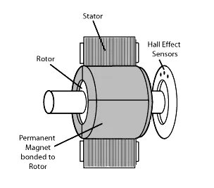
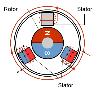
The Control unit is implemented by microelectronic has several high-tech choices. This may be implemented using a micro-controller, a dedicated micro-controller, a hard-wired microelectronic unit, a PLC, or similar another unit.
The Analog controller is still using, but the can not process feedback messages and control accordingly. With this type of control circuits, it is possible to implement high-performance control algorithms, such as vector control, field-oriented control, high-speed control all of which are related to electromagnetic state of the motor. Furthermore outer loop control for various dynamics requirements such as sliding motor controls, adaptive control, predictive control…etc are also implemented conventionally.
Besides all these, we find high-performance PIC (Power Integrated Circuit), ASIC (Application Specific Integrated Circuits) …etc. that can greatly simplify the construction of the control and the power electronic unit both. For example, today we have complete PWM (Pulse Width Modulation) regulator in a single IC that can replace the entire control unit in some systems. Compound driver IC can provide the complete solution of driving all six power switches in a three-phase converter. There are numerous similar integrated circuits with more and more adding day by day. At the end of the day, system assembly will possibly involve only a piece of control software with all hardware coming to the right shape and form.
PWM (Pulse Width Modulation) wave can be used to control the speed of the motor. Here the average voltage is given or the average current flowing through the motor will change depending on the ON and OFF time of the pulses controlling the speed of the motor i.e. The duty cycle of the wave controls its speed. On changing the duty cycle (ON time), we can change the speed. By interchanging output ports, it will effectively change the direction of the motor.
Advantages:
- Better speed versus torque characteristics
- High dynamic response
- High efficiency
- Long operating life due to a lack of electrical and friction losses
- Noiseless operation
- Higher speed ranges
Applications:
The cost of the Brushless DC Motor has declined since its presentation, because of progressions in materials and design. This decrease in cost, coupled with the numerous focal points it has advantage over the Brush DC Motor, makes the Brushless DC Motor a popular component in numerous distinctive applications. Applications that use the BLDC Motor include:
- Consumer electronics
- Transport
- Heating and ventilation
- Industrial engineering
- Model engineering