Study on Power Electronics, Duty cycle of a Power Electronics system
1. Why power electronics circuits are efficient? In practice, which types of losses occur in power electronics circuits?
Answer:
Power Electronics
Power electronics is the technology associated with the efficient conversion, control and conditioning of electric power by static means from its available input form into the desired electrical output form.
Power electronic converters can be found wherever there is a need to modify the electrical energy form (i.e. modify its voltage, current or frequency.) With “classical” electronics, electrical currents and voltage are used to carry information, whereas with power electronics, they carry power. Some examples of uses for power electronic systems are DC/DC converters used in many mobile devices, such as cell phones or PDAs, and AC/DC converters in computers and televisions. Large scale power electronics are used to control hundreds of megawatt of power flow across our nation.
Research in this area includes power electronics applications to control large scale power transmission and distribution as well as the integration of distributed and renewable energy sources into the grid. NCSU also has a strong program on the emerging applications of wide bandgap semiconductor devices that offer high oeprating temperatures, higher efficiency and higher power density.
Power Electronics embraces the studies of:-
(a) Power:-
It deals with both rotating and static equipment for the generation, transmission, distribution and utilisation of vast quantities of electrical power.
(b) Electronics:-
It deals with the study of semiconductor devices and circuits for the processing of information at lower power levels.
(c) Control:-
In deals with the stability and response characteristics of closed loop system.
Power Electronics deals with the use of electronics for control and conversion of large amount of electrical power.
Power electronic circuits are efficient because
- High efficiency due to low loss in power semiconductor devices.
- High reliability of power electronic converter system.
- Long life and less maintenance due to absence of any moving parts.
- Flexibility in operation
- Fast dynamic response compared to electromechanical converter system.
- Small size and less weight, thus low installation cost.
Power Losses in power electronic systems
Power losses (Pl) in any component operating in the switch-mode can be divided in three groups:
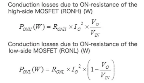
a) Conduction losses (Pc)
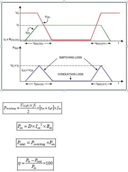
b) Switching losses (Psw)
c) Blocking (leakage) losses (Pb), normally being neglected
Therefore:
Pl = Pc + Psw + Pb ≈ Pc + Psw
conduction losses
Conduction losses occur when the device is in full conduction. The current in the device is whatever is required by the circuit and the voltage at its terminals is the voltage drop due to the device itself. These losses are in direct relationship with the duty cycle.
Switching losses
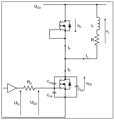
The circuit for the examination of the MOSFET switching losses is presented in the above figure. It is a single-quadrant chopper supplying an inductive type load. The MOSFET is driven from the driver circuit, providing a voltage UDr at its output. The MOSFET internal diode is used as a free-wheeling diode, because in the majority of applications, such as 3-phase AC motor drives, DC-motor drives, synchronous DC/DC converters, etc., the power electronics converter consists of one or more MOSFET-based half-bridges. If an external freewheeling diode is used, the calculations are still valid, provided the diode parameters are taken from the diode data-sheet
________________________________________________________________________________________________________________________
2. Using a suitable MATLAB model, show how duty cycle control signal can be generated for a simple power converter circuit?
Answer:
Boost converter
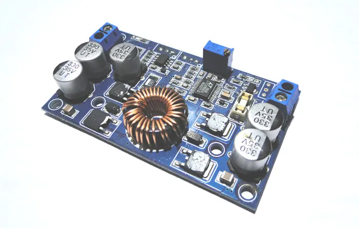
A boost converter is one of the simplest types of switch mode converter. As the name suggests, it takes an input voltage and boosts or increases it. All it consists of is an inductor, a semiconductor switch (these days it’s a MOSFET, since you can get really nice ones these days), a diode and a capacitor. Also needed is a source of a periodic square wave.
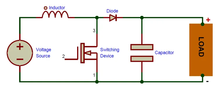
How does boost converter work?
It’s time to take a really deep breath, we’re about to plunge into the depths of power electronics. I’ll say at the outset that it is a very rewarding field.
To understand the working of a boost converter, it is mandatory that you know how inductors, MOSFETs, diodes and capacitors work.
With that knowledge, we can go through the working of the boost converter step by step.
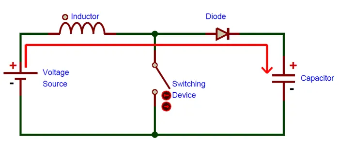
STEP – 1
Here, nothing happens. The output capacitor is charged to the input voltage minus one diode drop.
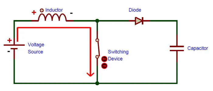
STEP – 2
Now, it’s time to turn the switch on. Our signal source goes high, turning on the MOSFET. All the current is diverted through to the MOSFET through the inductor. Note that the output capacitor stays charged since it can’t discharge through the now back-biased diode.
The power source isn’t immediately short circuited, of course, since the inductor makes the current ramp up relatively slowly. Also, a magnetic field builds up around the inductor. Note the polarity of the voltage applied across the inductor.
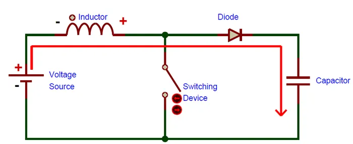
STEP – 3
The MOSFET is turned off and the current to the inductor is stopped abruptly.
The very nature of an inductor is to maintain smooth current flow; it doesn’t like sudden changes in current. So it does not like the sudden turning off of the current. It responds to this by generating a large voltage with the opposite polarity of the voltage originally supplied to it using the energy stored in the magnetic field to maintain that current flow.
If we forget the rest of the circuit elements and notice only the polarity symbols, we notice that the inductor now acts like a voltage source in series with the supply voltage. This means that the anode of the diode is now at a higher voltage than the cathode (remember, the cap was already charged to supply voltage in the beginning) and is forward biased.
The output capacitor is now charged to a higher voltage than before, which means that we have successfully stepped up a low DC voltage to a higher one!
These steps happen many thousands of times (depending on the frequency of the oscillator) to maintain the output voltage under load.
Simulink model
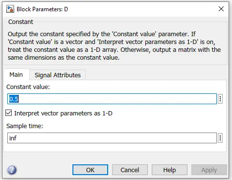
Duty cycle D = 0.5
`V_(out)/V_(i n)=1/(1-D)`
Here the converter is feeding an RC load from a 24V source and the PWM frequency is set to 20 kHz
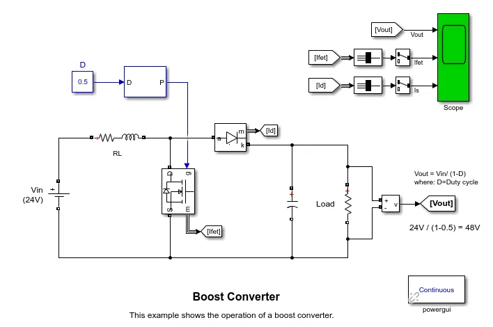
`V_(out)=V_(i n)/(1-D)`
`V_(out)=24/(1-0.5)=48V`
Output
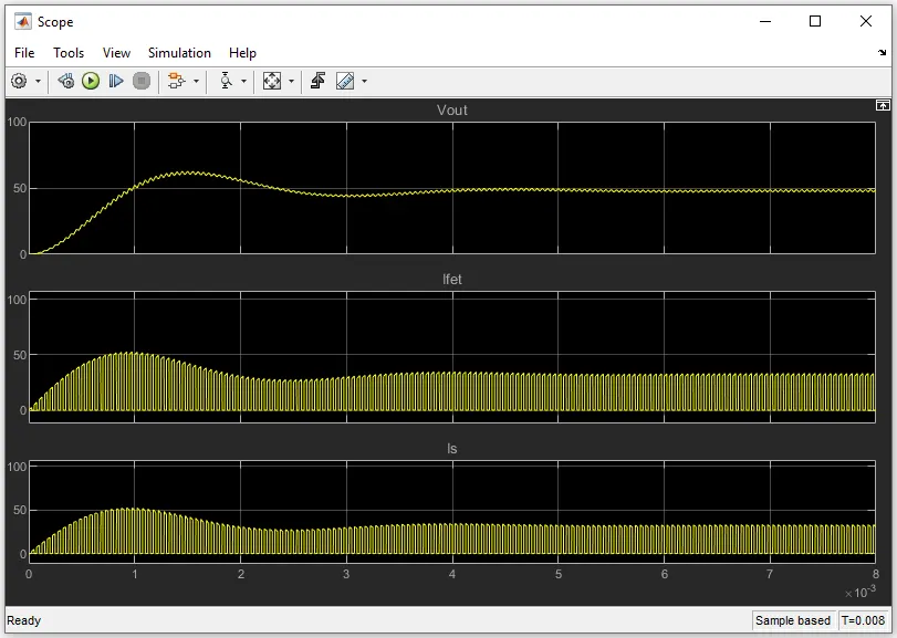
From the plot the mean value of the load voltage is very close to the calculated value ie `V_(out)=48V`
When duty cycle D=0.75
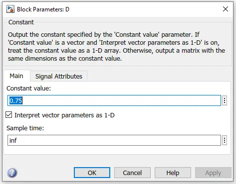
`V_(out)=24/(1-0.75)=96V`
Output
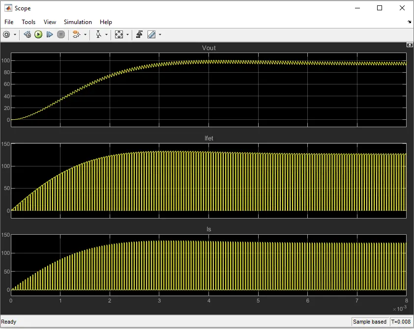
From the plot the mean value of the load voltage is very close to the calculated value ie `V_(out)=96V`
By this we can conclude that by changing duty cycle we can control power converter circuit.
________________________________________________________________________________________________________________________
3. Make a comparison of square wave inverter output voltage with sine modulated one.
Answer:
Inverter
An inverter can be defined as it is a compact and rectangular shaped electrical equipment used to convert direct current(DC) to aleternating current voltage(AC) in common appliances. The applications of DC involves several small types of equipment like solar power systems. Direct current is used in many of the small electrical equipment such as solar power systems, power batteries, power-sources, fuel cells because these are simply produced direct current.
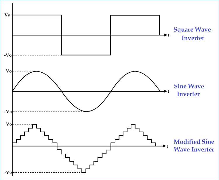
According to the output characteristic of an inverter, there can be three different types of inverters.
- Square Wave Inverter
- Sine Wave Inverter
- Modified Sine Wave Inverter
Square wave inverter
The output waveform of the voltage for this inverter is a square wave. This type of inverter is least used among all other types of inverter because all appliances are designed for sine wave supply. If we supply square wave to sine wave based appliance, it may get damaged or losses are very high. The cost of this inverter is very low but the application is very rare. It can be used in simple tools with a universal motor.
Sine wave
Modified sine wave
The construction of this type of inverter is complex than simple square wave inverter but easier compared to the pure sine wave inverter. The output of this inverter is neither pure sine wave nor the square wave. The output of such inverter is the some of two square waves. The output waveform is not exactly sine wave but it resembles the shape of a sine wave.
Modified sine wave is designed to simulate a sine wave since the generation of sine wave is expensive. This waveform consists of a Flat Plateau of positive voltage, dropping abruptly to zero for a short period, then dropping again to a flat plateau of negative voltage. It then go back to zero again and returning to positive. This short pause at zero volts gives more power to 50 Hz fundamental frequency of AC than the simple square wave.

Inverters providing modified sine wave can adequately power most house hold appliances. It is more economical but may present certain problems with appliances like microwave ovens, laser printers, digital clocks and some music systems. 99% of appliances run happily in modified sine wave. Instruments using SCR (Silicon Controlled Rectifier) in the power supply section behave badly with modified sine wave. The SCR will consider the sharp corners of the sine wave as trashes and shut off the instrument. Many of the Laser printers behave like this and fail to work in inverters and UPS providing modified sine wave power. Most variable speed fans buzz when used in modified sine wave inverters.
________________________________________________________________________________________________________________________
4. Explain the difference between VFD and Vector control drive. Can we use VFD method for induction motor in EV application?
Answer:
Variable Frequency Drive (VFD)
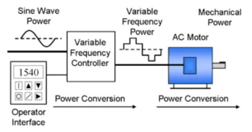
A VFD is a type of motor controller that drives an electric motor by varying the frequency and voltage supplied to the electric motor. Other names for a VFD are variable speed drive, adjustable speed drive, adjustable frequency drive, AC drive, microdrive, and inverter.
Frequency (or hertz) is directly related to the motor’s speed (RPMs). In other words, the faster the frequency, the faster the RPMs go. If an application does not require an electric motor to run at full speed, the VFD can be used to ramp down the frequency and voltage to meet the requirements of the electric motor’s load. As the application’s motor speed requirements change, the VFD can simply turn up or down the motor speed to meet the speed requirement.
VFD for AC motors have been the innovation that has brought the use of AC motors back into prominence. The AC-induction motor can have its speed changed by changing the frequency of the voltage used to power it. This means that if the voltage applied to an AC motor is 50 Hz (used in countries like China), the motor works at its rated speed. If the frequency is increased above 50 Hz, the motor will run faster than its rated speed, and if the frequency of the supply voltage is less than 50 Hz, the motor will run slower than its rated speed. According to the variable frequency drive working principle, it's the electronic controller specifically designed to change the frequency of voltage supplied to the induction motor.
Vector Control Drive
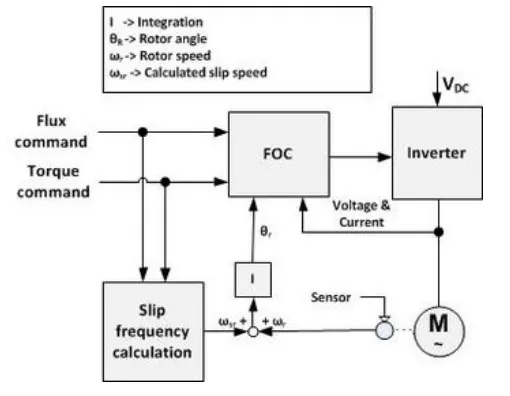
Vector control, also called field-oriented control (FOC), is a VFD control method in which the statpr currents of a thre-phase AC electric motor are identified as two orthogonal components that can be visualized with a vector. One component defines the magnetic flux of the motor, the other the torque. The control system of the drive calculates the corresponding current component references from the flux and torque references given by the drive's speed control. Typically PI controllers are used to keep the measured current components at their reference values. The pulse-width modulation of the variable-frequency drive defines the transistor switching according to the stator voltage references that are the output of the PI current controllers.
VFD vs VCD
All AC drives regardless of control technique are variable frequency drives (VFD) or variable speed drives (VSD). There are various control techniques which may be applied such as
- Scalar Control (V/f)
- Vector Control
- Direct Torque C0ntrol
- Slip Control
- and many others
V/F control mode: Just like driving a car, the throttle opening on your feet stays the same status, while the car speed is definitely changing becaues the road on which the car is running is uneven, and the road obstruction is also changing. Therefore, when you go uphill, the speed will slow down while it will go up when you go downhill, right? For the frequency converter, the frequency you set is just like the throttling opening of your car. In V/F control mode, the throttle opening is fixed.
Vector control mode: It can control the car to keep the speed constant and improve the speed control accuracy under the changes of road conditions, obstruction, uphill and downhill. Then, in order to ensure that the speed is stable and constant regardless of these changes, the throttle opening must be adjusted accordingly, right? At this time, the speed you set is just like the throttle opening, the set value is not changed, how does the throttle opening change and adjusted with the changes of road conditions? In fact, when you choose ‘vector control’, CPU inside the drive opens this special function! Utilize the feedback from the motor current change, through the internal solidified program and formula of the CPU, through the internal PID regulator of the CPU to increase or decrease the opening degrees of throttles (the oil intakes of engine) on the basis of your original throttle opening degree, So, seemingly, both in V/F control and vector control mode, your throttle openings both have no change, but, actually, V/F control indeed does not change the throttle opening, while for the 'vector control', the throttle opening is actually variable (adjusted up and down on your original throttle opening). So that, the speed can be kept the same as much as possible.