Study of Induction Motor Characteristics using MATLAB
- How induction motor operation is similar to the clutch?
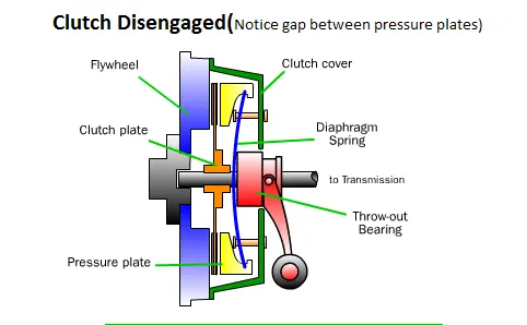
A clutch is a mechanical device which engages and disengages power transmission from driving shaft to driven shaft.
In a car, you need a clutch because the engine spins all the time, but the car's wheels do not. In order for a car to stop without killing the engine, the wheels need to be disconnected from the engine somehow. The clutch allows us to smoothly engage a spinning engine to a non-spinning transmission by controlling the slippage between them.
Clutch Disengaged
Clutch engaged
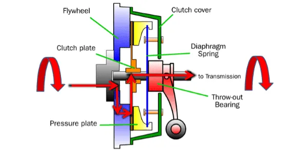
Working:
When the clutch pedal is pressed, a cable or hydraulic piston pushes on the release fork, which presses the throw-out bearing against the middle of the diaphragm spring. As the middle of the diaphragm spring is pushed in, a series of pins near the outside of the spring causes the spring to pull the pressure plate away from the clutch disc (see below). This releases the clutch from the spinning engine.
Note the springs in the clutch plate. These springs help to isolate the transmission from the shock of the clutch engaging.
Induction motor
The induction motor also operates in a similar way of the mechanical clutch.
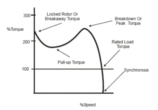
The above figure we can say that the motor is functional only between synchronous speed and breakover troque point where load is engaged.
From the starting torque point to the breaking torque point the motor is not operational to overcome the given load.
After brekover torque point to the synchronous speed point the motor is operational with load engaged and this satsifies the steady state stability condition of the induction motor.
This is also similar to a operation of mechanical clutch, where the load is engaged when speed rises. The load torque is also higher than the motor torque, thus limits the speed by not reaching infinite values and also does not reduce the spinning speed of the motor to 0.
Induction motor operates in a similar way of transmiting the speed and torque from the stator to the rotor.
therefore,
rotor speed is given by reducing the slip from the stator synchronous speed,
`omega_m=omega_(ms)(1-S)`
`omega_m=`rotor speed, `omega_(ms)=`synchronous speed and S=slip
________________________________________________________________________________________________________________________
2. Calculate the starting time of a drive with the following parameters
J=10 kg-m2,
T = 15 + 0.5wm
Tl=5+0.6ωm
where, J- moment of inertia T -motor torque `T_l`- load torqe
wkt, stability eq
`T_m=T_l+J((domega_m)/dt)`
t -starting time of motor
in ideal condition,
`T_m=T_l`
therefore,
`15+0.5omega_m=5+0.6omega_m`
clear all
close all
clc
w = linspace(0,200,500); %motor speed
tm = 15 + 0.5*w; %motor torque
tl = 5 + 0.6*w; %load torque

%plotting
plot(w,tm,'linewidth',2,'color','r');
hold on
plot(w,tl,'linewidth',2,'color','b');
title('Speed vs Troque')
xlabel('Motor speed in rad/sec')
ylabel('Torque in Nm')
legend('Motor Torque','Load Torque');
grid on
output:
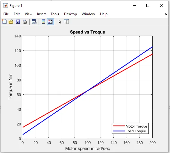
from graph the curves intersect at steady state motor speed is 100rad/sec.
Steady state equation to calculate statring time,
`T_m=T_l+J((domega_m)/dt)`
subsituting the values
`15+0.5omega_m=5+0.6omega_+10(domega_m)/dt`
`dt=1/(1-0.01omega_m)domega_m`
to find t
`intdt=int1/(1-0.01omega_m)domega_m`
Main coding for calculation
clear all
close all
clc;

t_span = linspace(0, 500, 500);
w_0 = [0 0];
[t, w] = ode45(@sbr, t_span,w_0);

plot(t, w, 'linewidth',2,'color','r')
grid on
xlabel('Time in Seconds')
ylabel('Motor Speed in rad/sec')
title('Motor Speed vs Time')
function coding
function[dw_dt] = sbr(t,w);

dw_dt = 1-0.01*w;
end
Output:
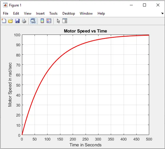
To achive steady state speed it takes infinite time to do so, in generel we want to know time taken from rest to 95% of steady state speed assuming 5% slip.
From graph we can say that time taken to reach 95% of steat state speed t=300secs.
___________________________________________________________________________________________________________
3. A drive has following equations for motor and load torques:
Tm=(1+2ωm)
Tl= 3 √ωm
Obtain the equillibrium points and determine the stability
INDUCTION MOTOR STABILITY
Is defined as the ability of the system to restore steady state when exposed to transient disturbance.
In ideal condition
`T_m=T_l`
`1+2omega_m=3sqrtomega_m`
The stability condition is:
`(dT_l)/(domega_m)-(dT_m)/(domega_m)>0`
clear all
close all
clc

x = linspace(0,5,20); % motor speed

y1 = 1+2*x;  %motor torque
y2 = 3*(x.^0.5);  % load torque


%plotting
plot(x,y1,'linewidth',2,'color','r');
hold on
plot(x,y2,'linewidth',2,'color','b');
title('Speed vs Troque')
xlabel('Motor speed in rad/sec')
ylabel('Torque in Nm')
legend('Motor Torque','Load Torque');
grid on
Output:
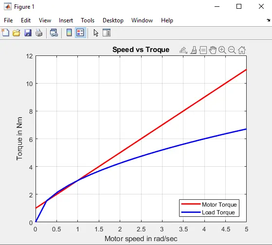
From above plot the curves intersects at two points ie, at 0.25rad/sec and 1rad/sec
At angular speed 1rad/sec the stability condition is not satisfied, hence the induction motor drive is stable at 0.25rad/sec.
It means that the induction motor is stable to operate at that speed.