Structural Modelling using Etabs 2018
Aim:
To model and analyse the given building.
Procedure :
Conceptual plan layout:
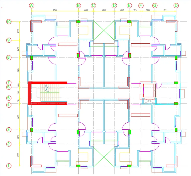
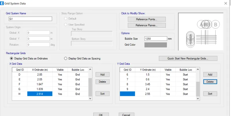
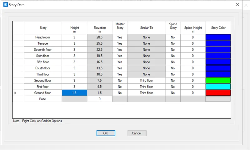
Grids and storey heights:
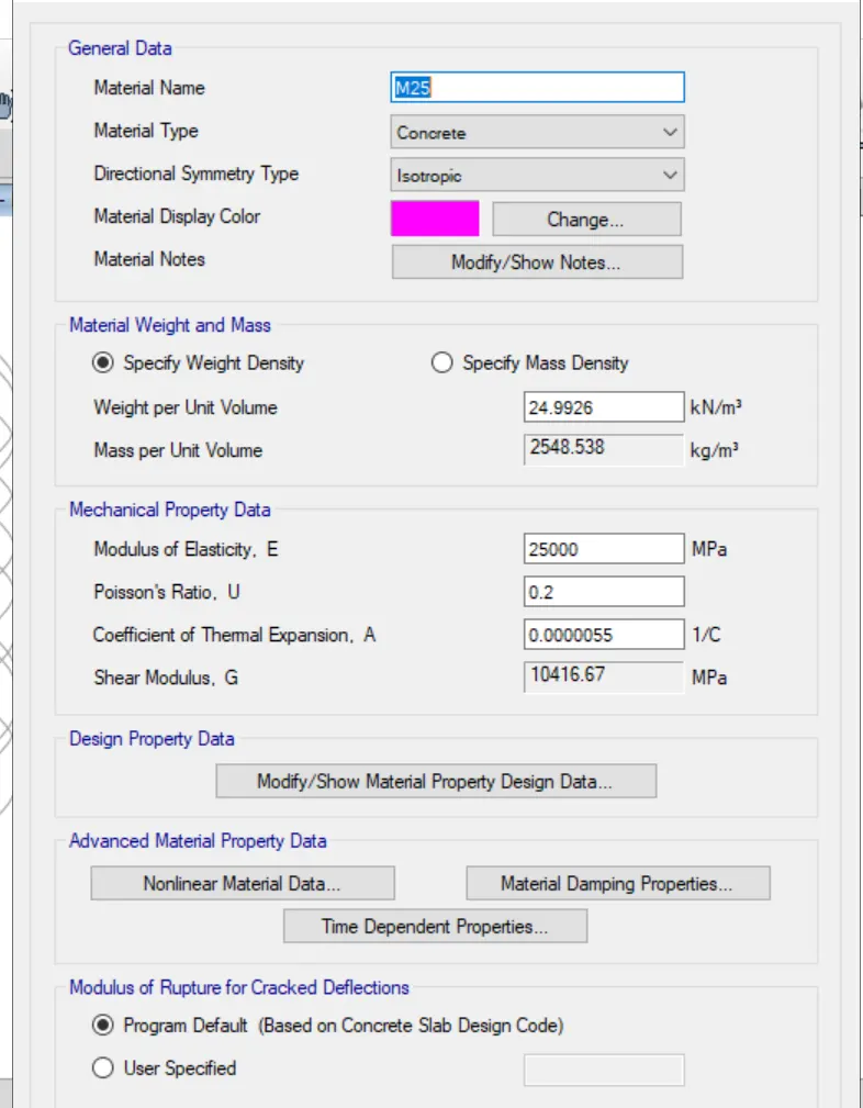
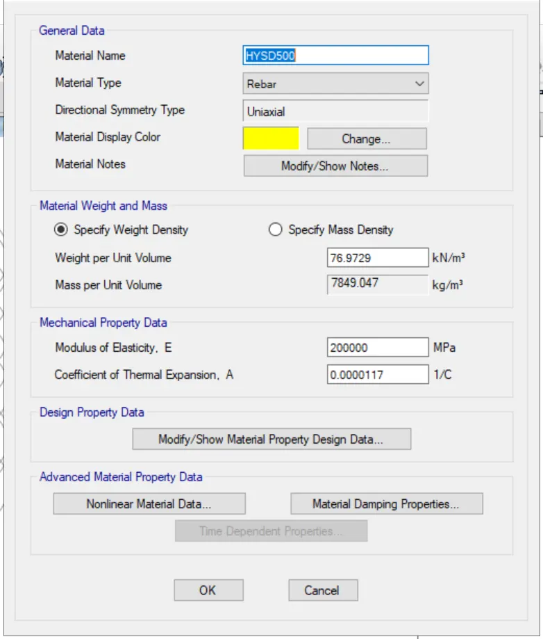
Material property:
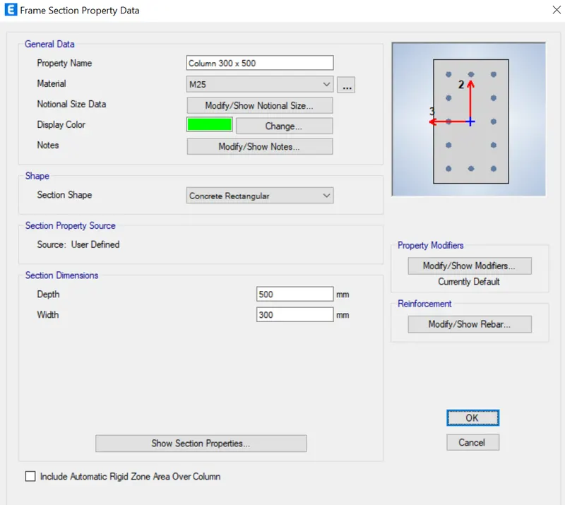
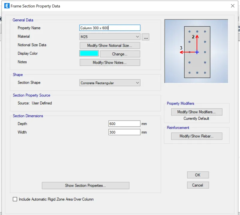
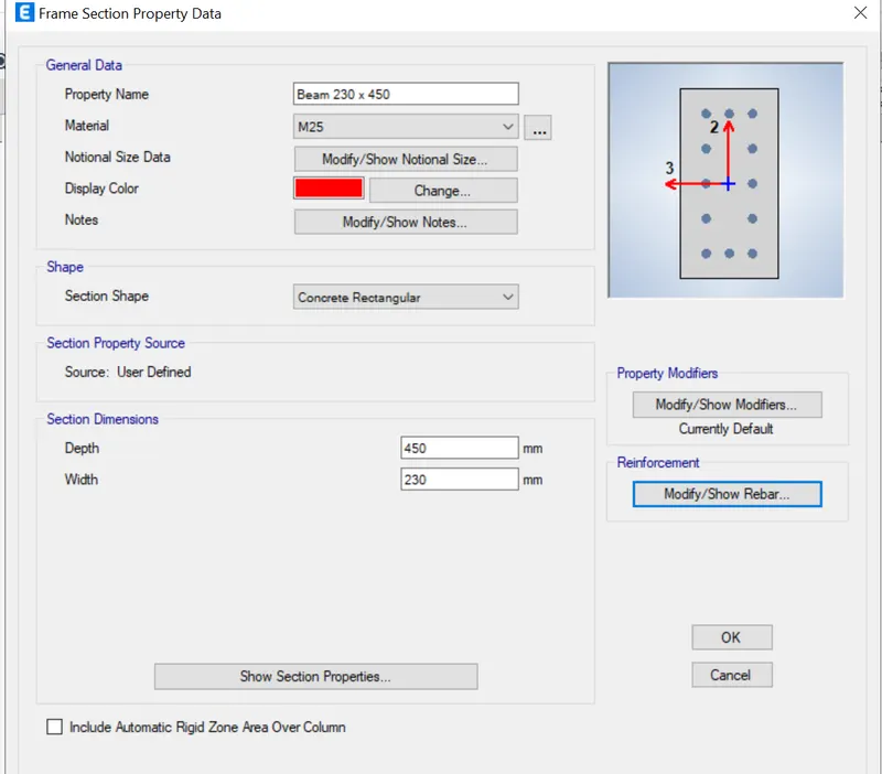
Section property:
Column:
Beam :
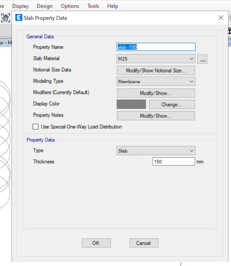
Slab:
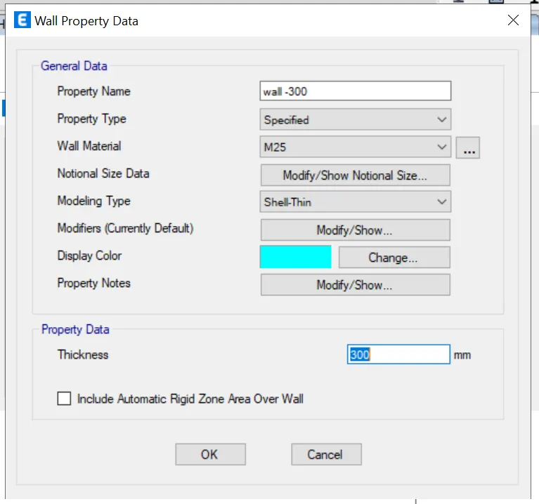
Wall:
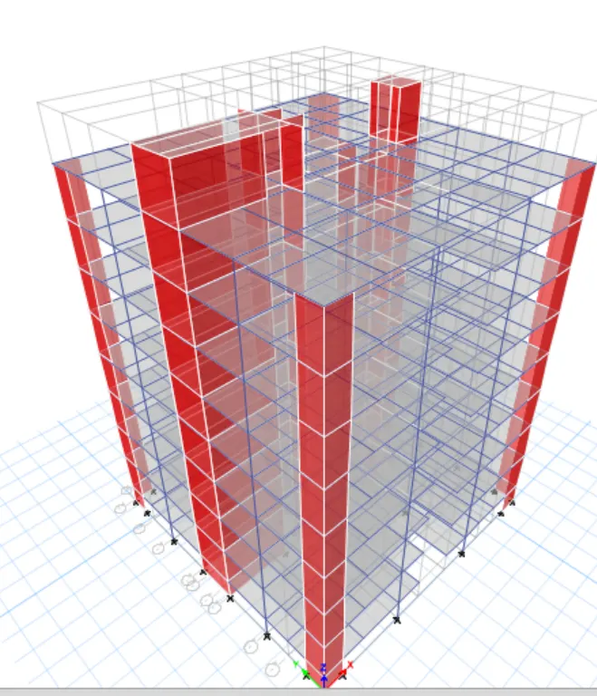
Modelling of beam,column,walls and slabs:
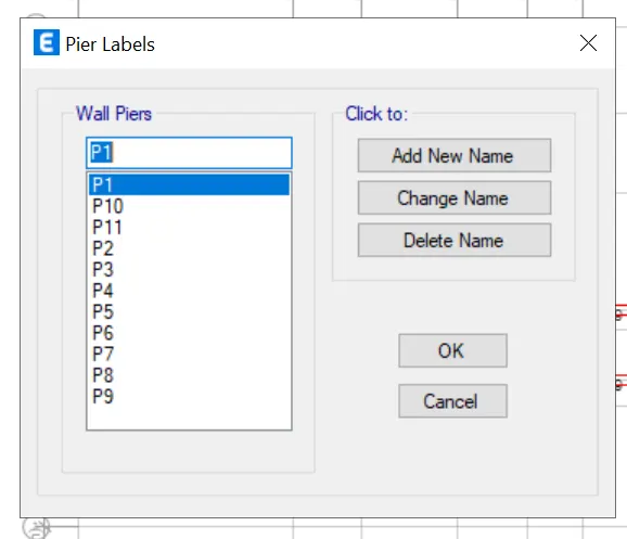
Pier assignments:
Based on the number of shear walls the pier assignments are done
Load pattern:
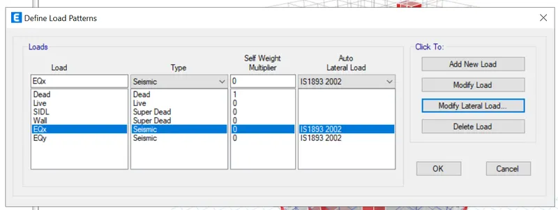
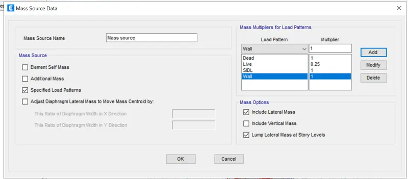
As per IS 1893-2016 live load factor is considered as 0.25 and Dead load factors are consirered as 1.
Mass source:
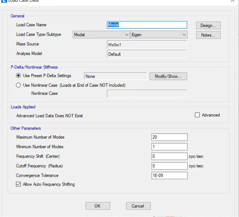
Definition of Modal analysis:
Click ---> define ---> Load case ---> Modal ---> Modify/show case---> change the maximum number of modes to 20
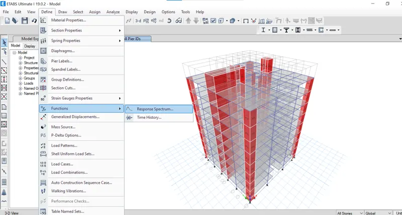
Response spectrum analysis:
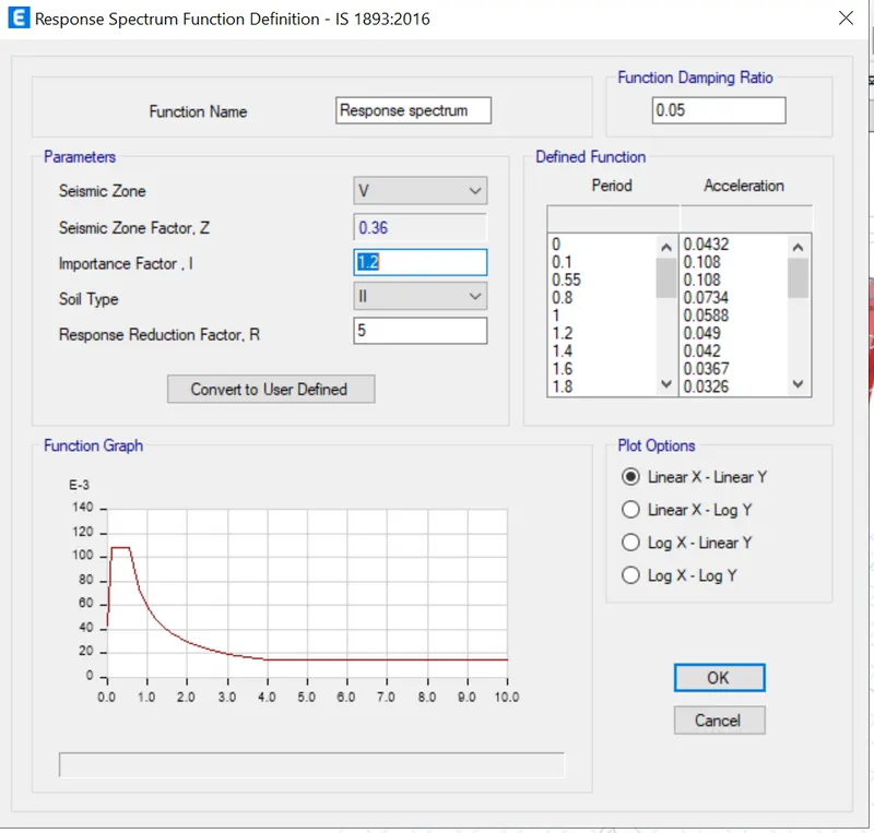
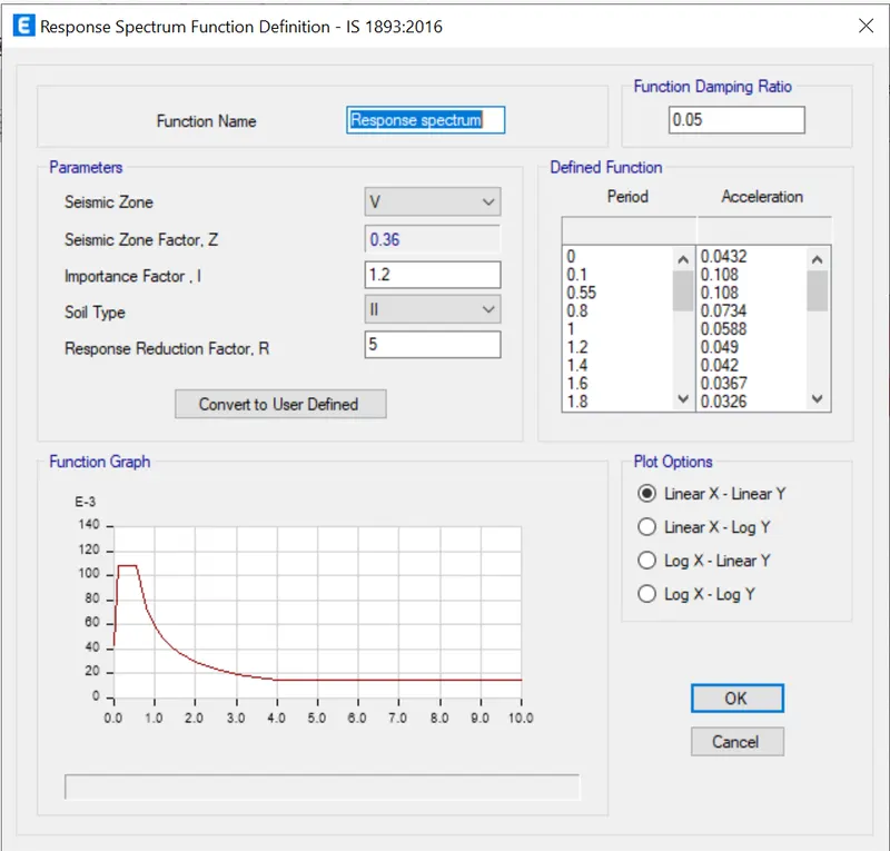
Click --> Define --> function --> Response spectrum --> add new function
Load combinations:
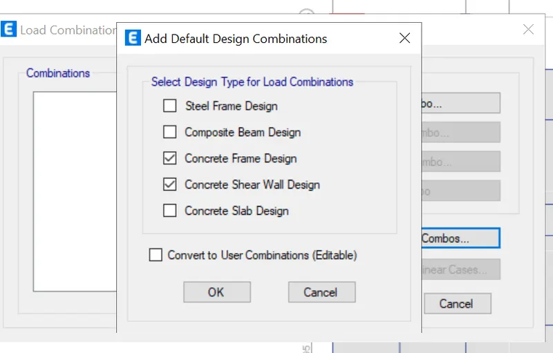
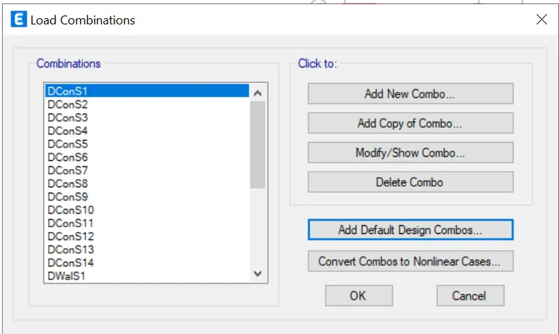
Define --> Load combinations --> Select concrete frame design and concrete shear wall design in load combinations.
Load assignments:
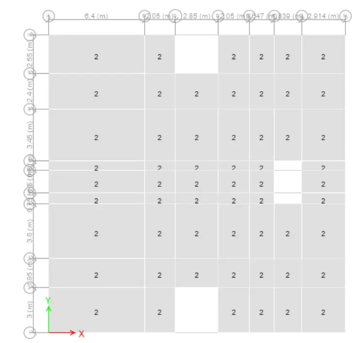
Live load:
Floor Finish:
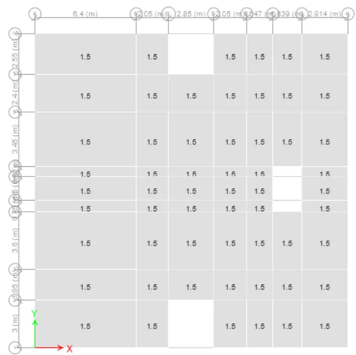
Wall load:
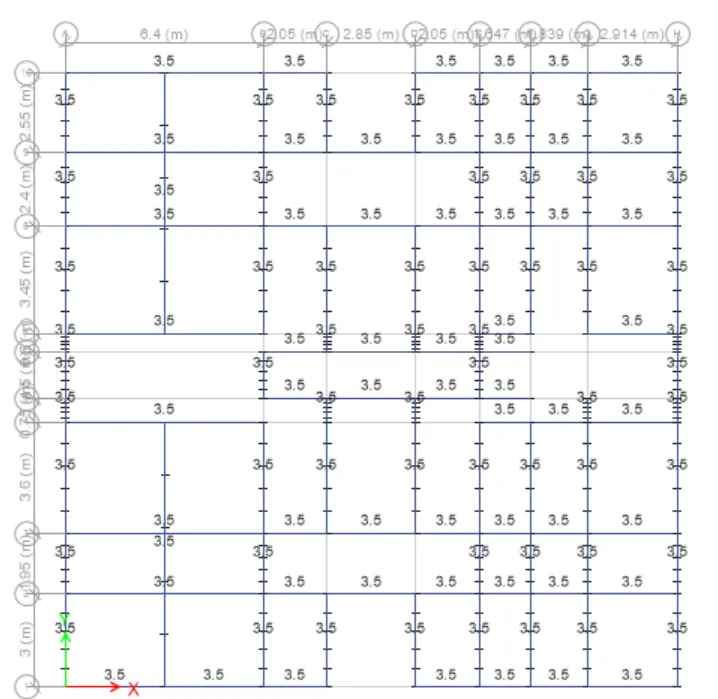
Apply the water tank load and lift room load in the Mumty level.
Assign the restraints at base all the joints are given pinned support.
Analysis:
Check the model for any errors.
If there is no error ---> Run analysis ---> start concrete frame design and slab design.
Results:
Tables --> Analysis results --> structure output --> Modal particpating mass ratio
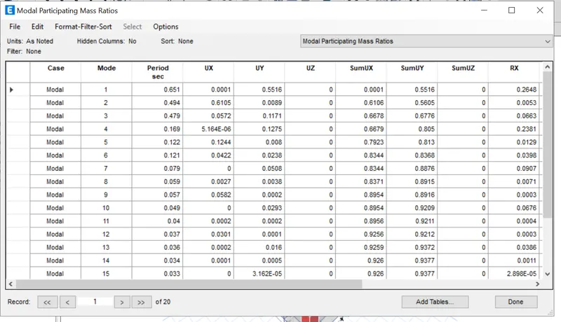
First two fundamental modal mass are greater than third one.
Inter storey drift:
In define --> functions --> response spectrum is defined as per IS1893 zone factor, importance factor are given.
Define --> load case --> Rsx and Rsy and initial scale factor
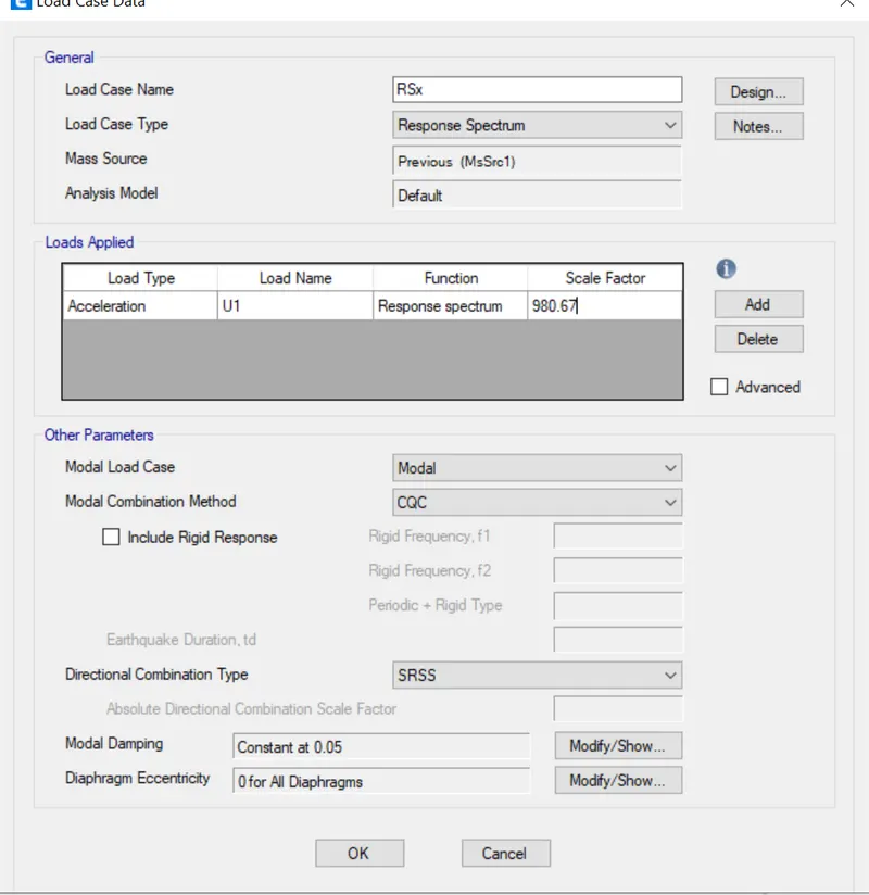
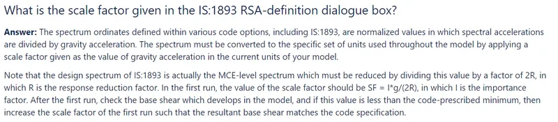
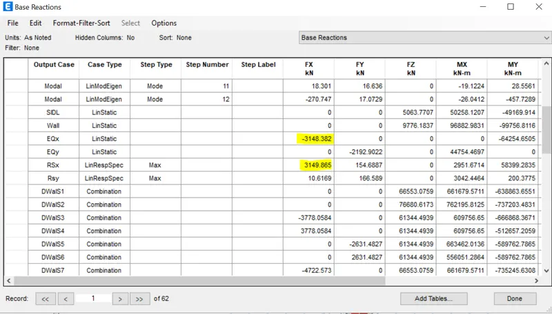
Run analysis and check the base reactions for the scale factor 980.67.
Base shear from equivalent load method and response spectrum method should be equal.
Inorder to make it equal, scale factor is obtained by Eqx/Rsx = Y
Multiply Y with 980.67 in response spectrum load case.
Inter storey drift:
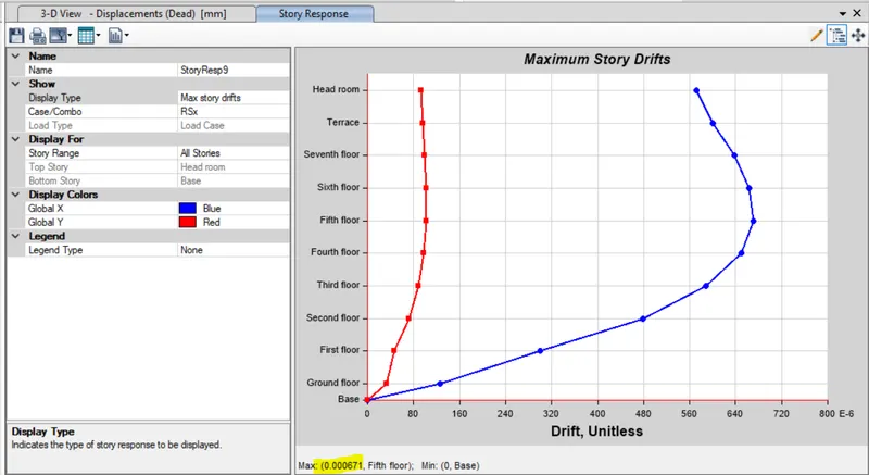
Inter storey drift is less than 0.004mm. Hence it is satisfied.
Column axial force:
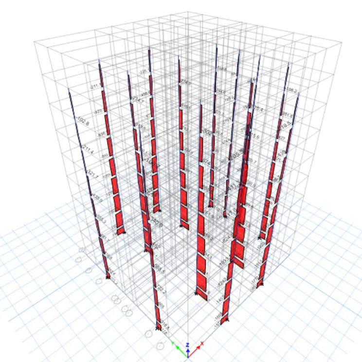
All the column axial forces are in compression.
Wall forces:
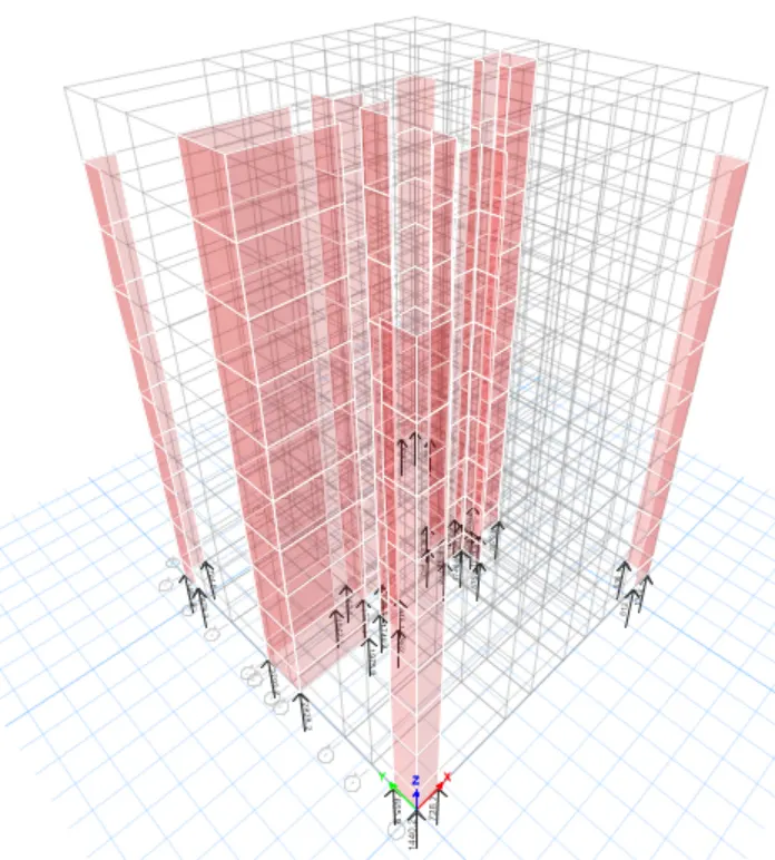
Base compressive stress of walls are checked within the limits 0.28fck.
Conclusion:
Thus conceptual seismic design is done for the given project.