Structural Modelling using Etabs 2018
Objective of this challenge is to model a multistory apartment with all seismic consideration based on IS codes according to the given architectural considerations.
Architectural drawing of a G+7 story building is given with a typical floor detail and parking section plan.
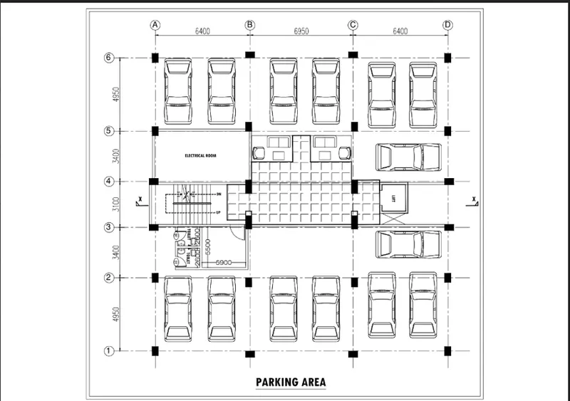
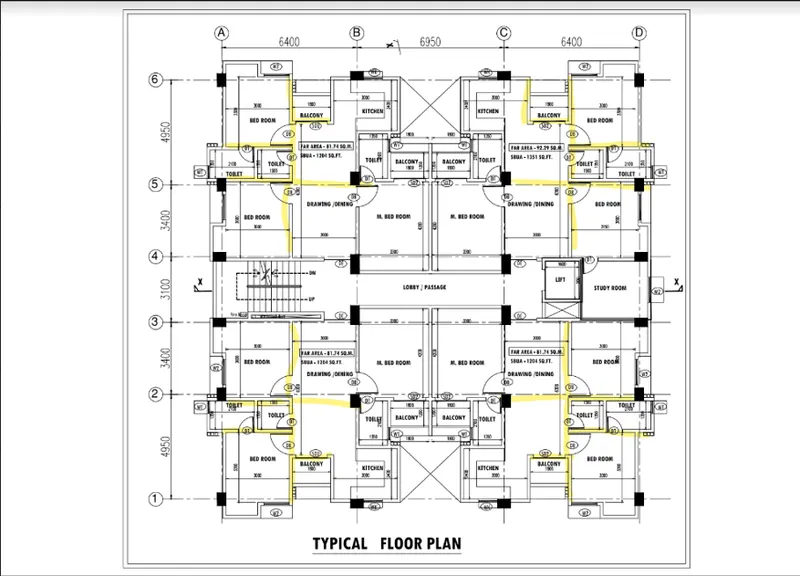
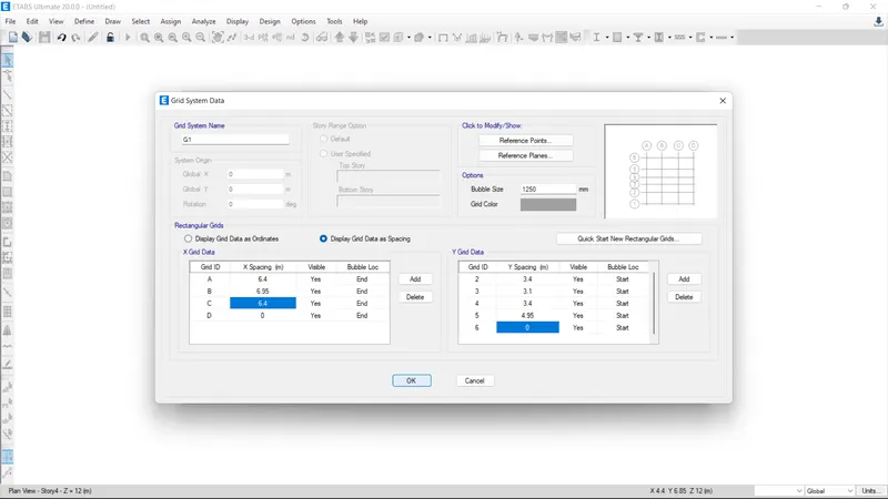
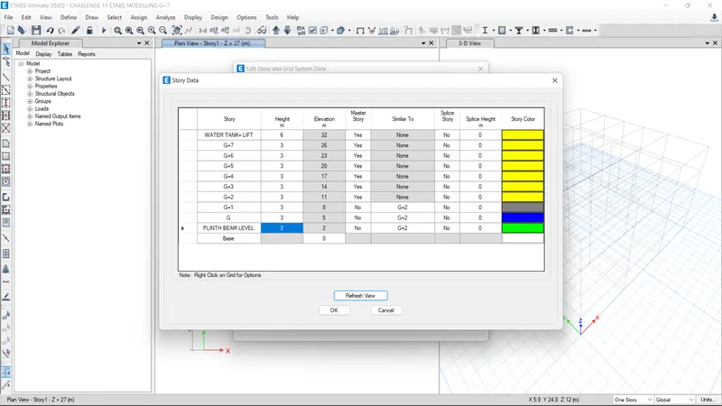
Grid data and storey data is shown in figure
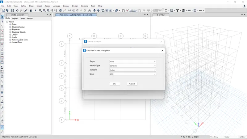
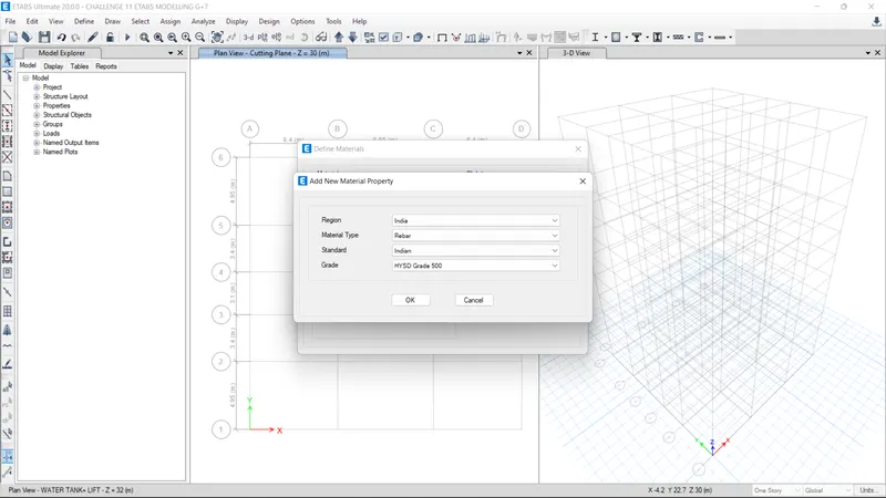
Material properties of steel and concrete ia shown in figure
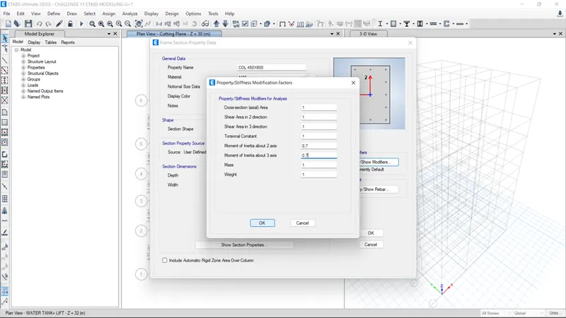
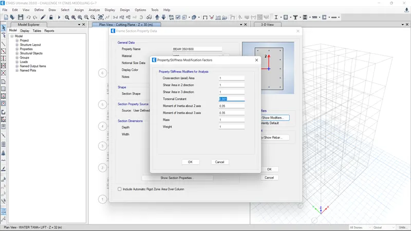
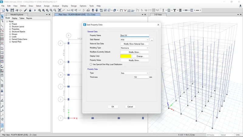
For initial framing plan considered the column size as 450mm x 600mm. Beam size 350mm x 600 mm. Slab Thickness 125 mm for all floors and Shear wall thickness of 300mm.
 .
.
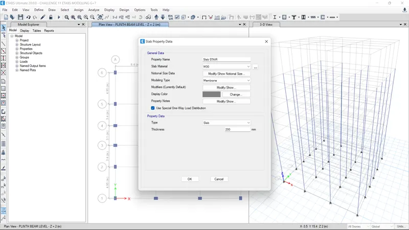
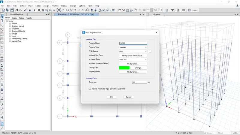
Concrete Grade for columns provided M35 and for Beams, Slabs,Stairs provided as M30.
FRAMING PLAN 1
Shear walls are provided at corners and middle area as shown in figure. Shear walls are not provided in the Lift Duct.
Typical Floor Plan
Plinth Beam Layout
Conceptual design considerations are
1) Re-entrant and cutout check and modification - Some times we have to co-operate with architects with aesthetics. Hence Cot outs and re-entrant corners are often un-avoidable
2)Vertical irregularities - Ground Floor consumes space for parking hence soft story mechanism can be observed
3) Planar irregularities- Symmetrical distribution of framing elemnts, hence the wont be any planar irregularities.
4) At least 2% of shear wall area to the total area ob building - Satisfied (Building area = 115m2, Shear wall area 16 nos x 1.2m x 0.3m = 5.76 m2 area ratio = (5.76/115) x 100 = 5%)
5) Stiffnes modifiers for Columns and beams and Shear walls - Considered 0.7 for vertical elemetns and 0.35 for beams
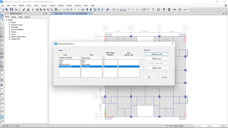
Assumed that all walls contains AAC Blocks with a UDL of 4kN/m. Floor Finishes 1.5 N/m2, Live loads 2kN/m2 and 3 Kn/m2 as per IS 875 part 2 for different usage spaces. Staircase slab is modelled as one way load distribution along longer span with LL 3kN/m2.
Beams and Columns modelled with effective moment of inertia 0.35I and 0.7I respectively in stiffness modifiers. We are not considering any torsion in our beams hence for beams torsional coefficient set very low value as shown
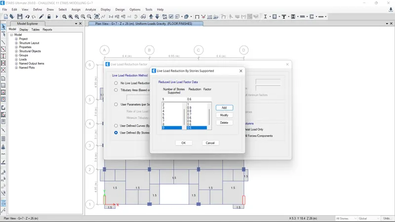
Live load reduction factors for all floors are considered as per Cl 3.2.1 IS 875 Part 2.
Load patterns are defined including both Gravity and Equivalent Lateral Load patters according to their resoective Indian standard codes as shown. For Earthquake loads eccecnticity and Direction id also defined accordingly.
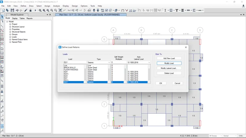
Modified all the EQ Loads with respect to the eccenticity allowed
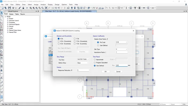
Similarly done for EQX+e EQX-e, EQY, EQY+e,EQY-e
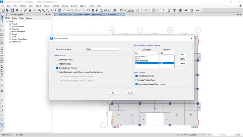
Mass source is defined for seismic weight calculation. For Live loads percentage loads considered for seismic weight as 25% as per Table 20 IS 1893:2016
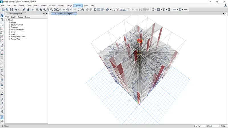
Diaphrams assigned for all slabs
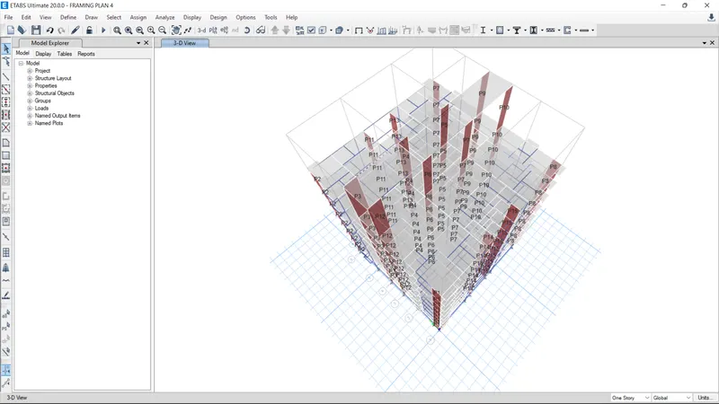
Individual pier labels assigned for all shear wall elements.
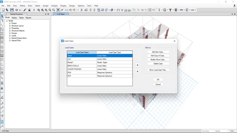
Defined all load cases to be set for the analysis
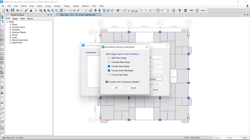
Defined all the load combinations for specified load combinations as per codes for frame and shear wall design.
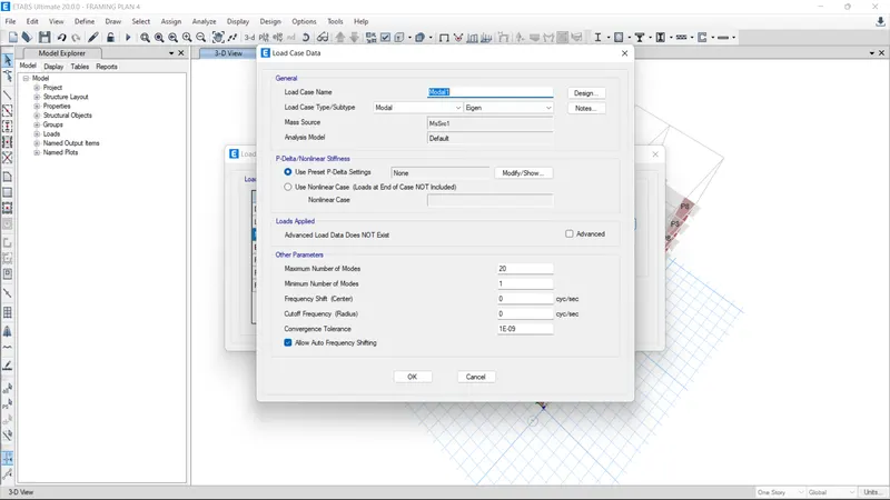
Defined Modal load case with subtype as Eigen. Intial number of modes assigned is 20 for initial framing design.
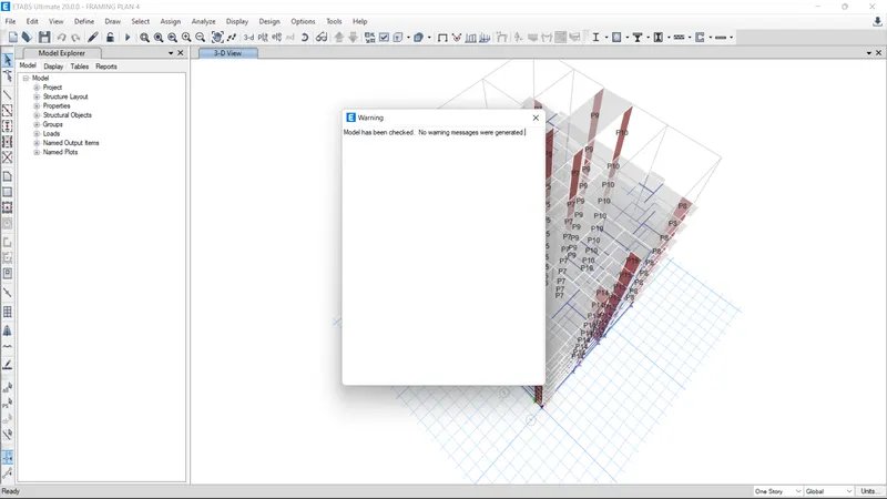
All errors has been solved and model is now ready for the analysis.
Defined Response Spectrum Function with all the data available
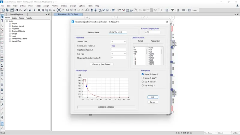
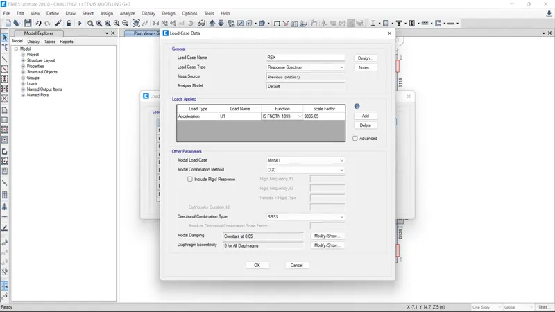
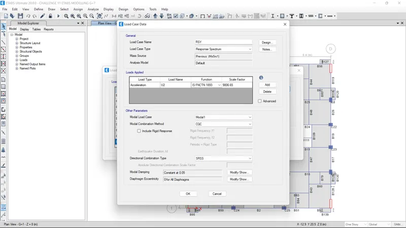
Scale factor = 9806
As per IS 1893:2016 Dynamic analysis may be performed by either THM or RSA, either of the method is used the design base shear VB estimated shall not be less than the design base shear VB' calculated using fundamental time period Ta.
obtained scale factor is multiplied with the value VB/VB'
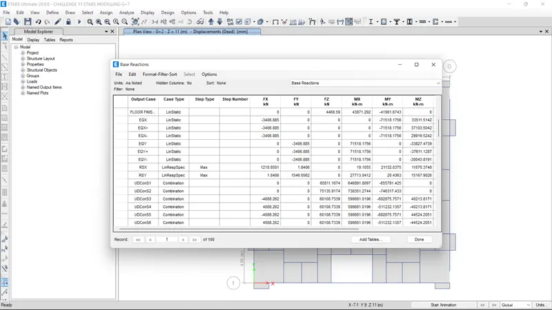
For U1 acceleration scale factor 9806.65 is multiplied with the value (VB/VB') = 3406.885/1218.85 = 2.79
9806.65 x 2.79 = 27411.11 shown in figure
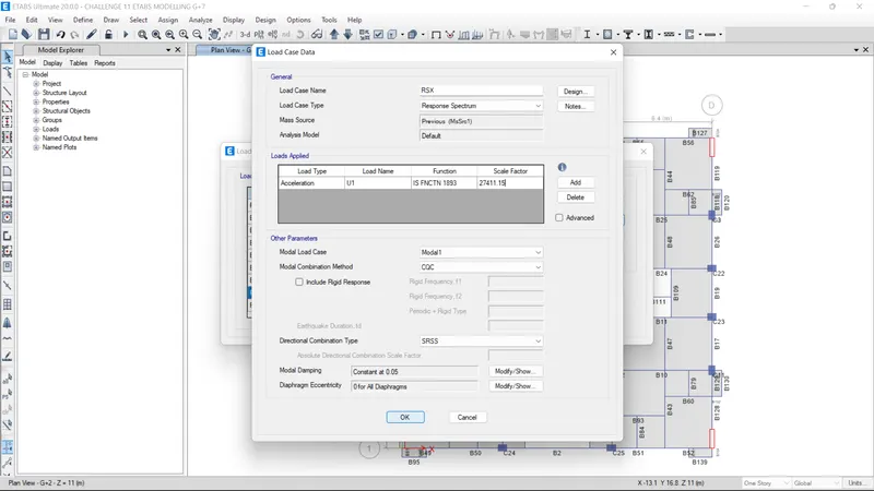
Same is done in the case for RSY
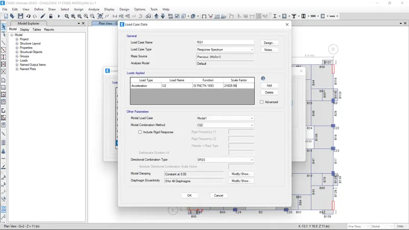
Now Re-run the analyisis and obtain the results
After the analysis some checks have been made
1) Modal mass participation for first three modes should dominates atleast 65% - Satisfied
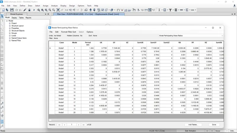
First two modes are dominated by translational modes and only third mode is contributed by rotation. Hence this framing plan can be provided under seismic loads comparing to modal mass partcipation gactores.
2) Time Periods of Mode 1 and Mode 2 differs by 10% - Not Satisfied

3) Time periods Principal modes are greater than Torsion mode - Satisfied
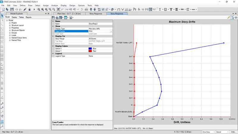
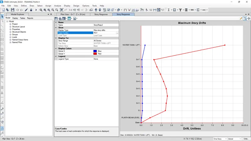
4) Inter story drift ratio limited to 0.004 - Story drift ratio restricted to 0.004 up to water tank level. But it Exceeds 0.004 on top story (Water Tank level)
5) Axial stresses in column and shear wall
Permissible Axial stress at column base is 0.4fck = 0.4x35 = 14 N/mm2
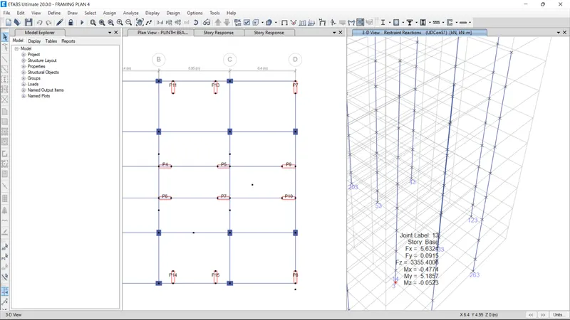
Maximum reaction obtained at base for any column is around is 3360 kN
Area of column = 450 mm x 600 mm = 270000 mm2
stress = 3360 x 10^3 / 270000 = 12.45 N/mm2 . Hence Satisfied
6) Base shear share b/w Shear walls and columns
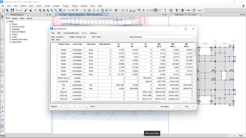
(Fx) total for RSX load case = 3654 kN
Sum of Fx for all shear walls from the modal = 3530 kN
Which is 96% of the total base shear. Major part of the base shear is taken by the shear walls hence it is shear wall system and Not a dual system
FRAMING PLAN 2
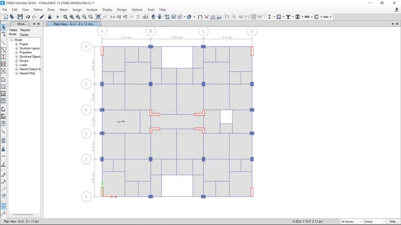
Position of shear walls has been changed towards middle of the building by keeping load cases, load patterns, load combinations, mass source etc the same. Material properties, sectional properties, loading etc are also kept same . exterior beams at cutouts where not removed
Analyisis completed and Results are shown below
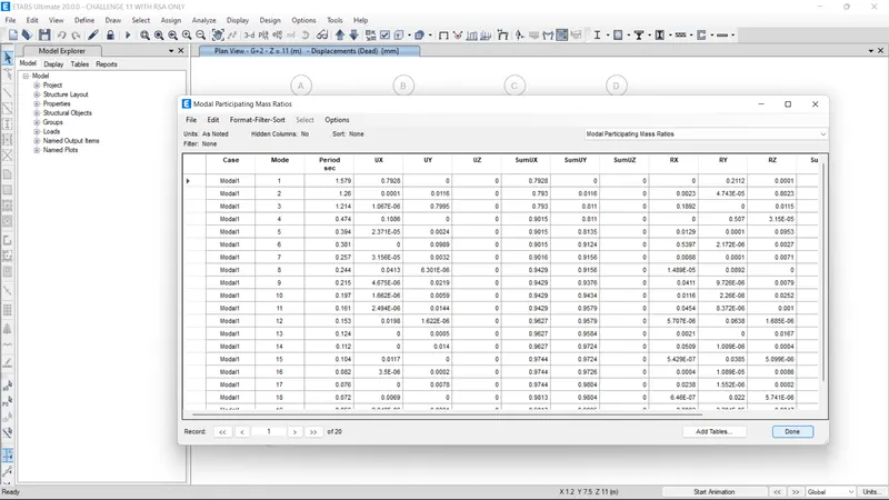
From the Modal mass participation factor table it is very clear that this framing plan is very sensitive in torsion than translation. Torsional mode dominates in Mode 2. More than 80% of the mass is participating in the torsion for the second mode which is not suitable under seismic loading. We need to add more shear walls perpendicular to the Y direction to take the torsion.
FRAMING PLAN 3
Provided Shear walls around the lift core (Common Practice) by keeping load cases, load patterns, load combinations, mass source etc the same. Material properties, sectional properties, loading etc are also kept same . exterior beams at cutouts where not removed
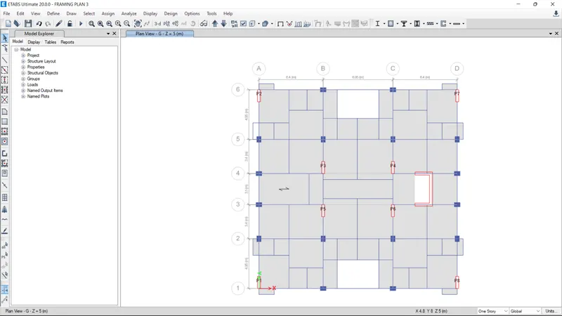
Analysis Results
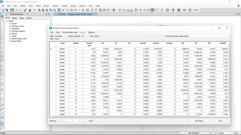
Here also like in framing plan two 2nd mode is dominated by torsion. Also the data is somewhat different from a stable configuration. Hence this framing plan is not safe under seismic loadings. We need to add more shear walls for counter the torsion in Y direction like framing plan 1
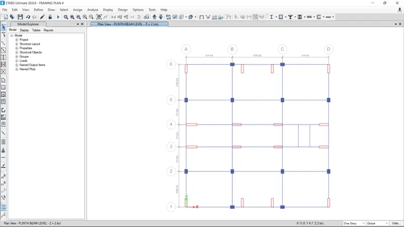
FRAMING PLAN 4
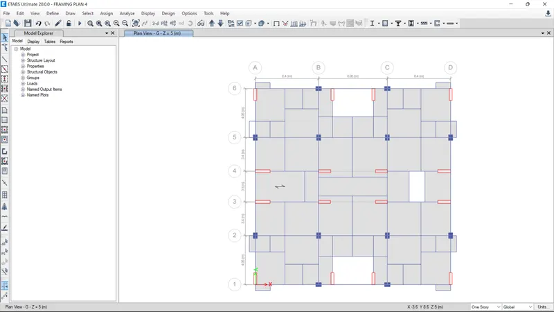
This plan is similar to Framing plan 1 as per the position and amount of shear walls are concerned. The exterior beams of cutouts is removed for the architectural point of view and for checking whether the plan obtaied so can able to prevent the rotation in first two modes. in other words removing the outer beams will reduce the lateral stiffness of the building or not.
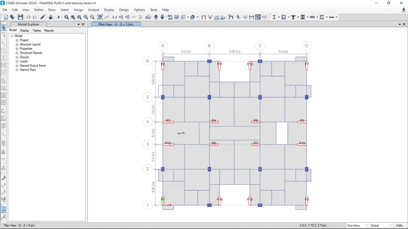
All the data kept same as Framing plan 1 expected the 2 beams removed.
Analysis results
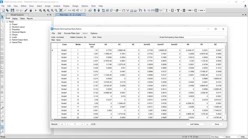
From the results it can be seen that removing the beams did not have an effect on lateral stiffness of the building. Only the third mode comes to rotation and first two modes remains as translational modes. which can be used under seismic loading. Here both structural and architectural features are combined.
CONCLUSIONS OF TASK 11
- For every building plan configurations there can be more one framing plans.
- Providing shear walls around lift core will not always make the building torsionally stable.
- Removing the exterior beams may nof affect the lateral stiffness of the building if we provide enough shear walls in the desired locations
- Shear walls plays a vital role in lateral stability of the buildings