Steering Kinematics - Geometric parameter calculations
AIM:
1. Calculate the following geometric parameters:
(i) Caster
(ii) Mechanical Trail
(iii) Kingpin Inclination Angle
(iv) Kingpin Longitudinal Offset
(v) Scrub Radius
(vi) Kingpin Lateral Offset or Spindle Length
GIVEN DATA:
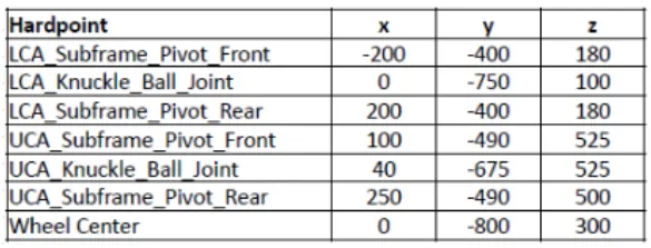
SOLUTION:
Sign Convention:
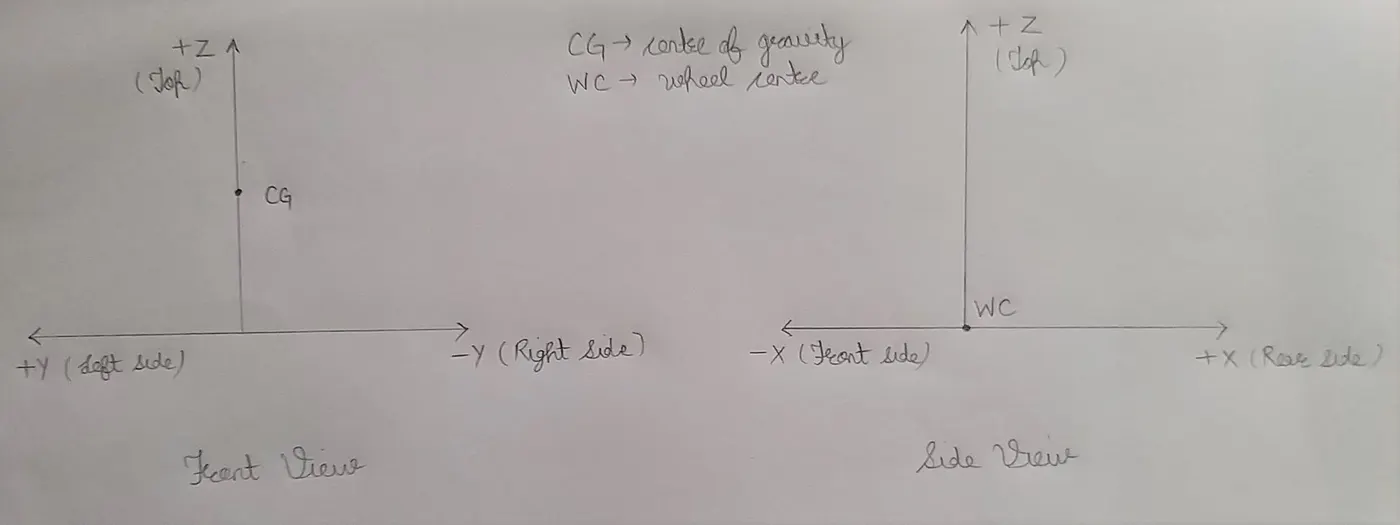
Geometric Representation:
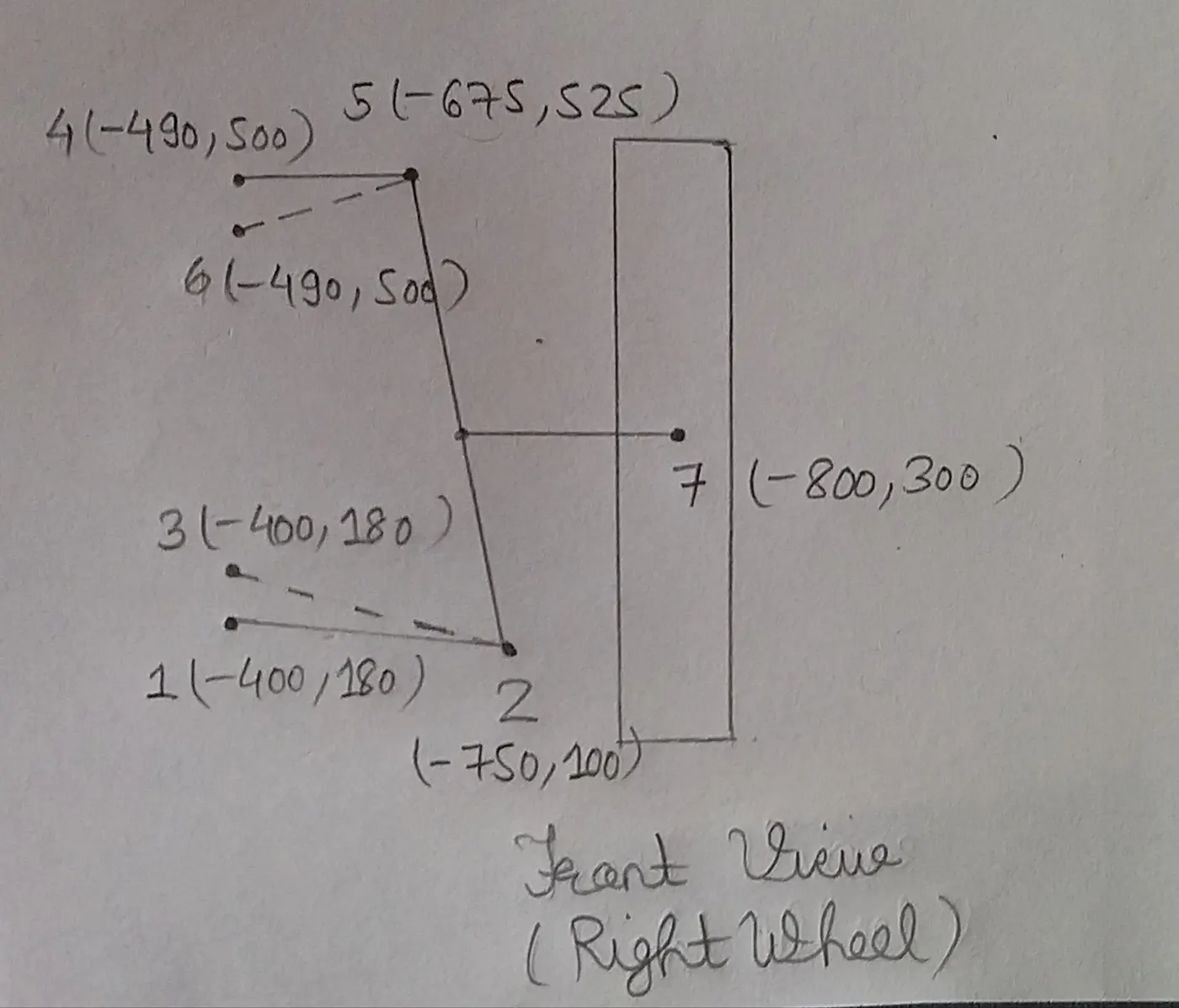 |
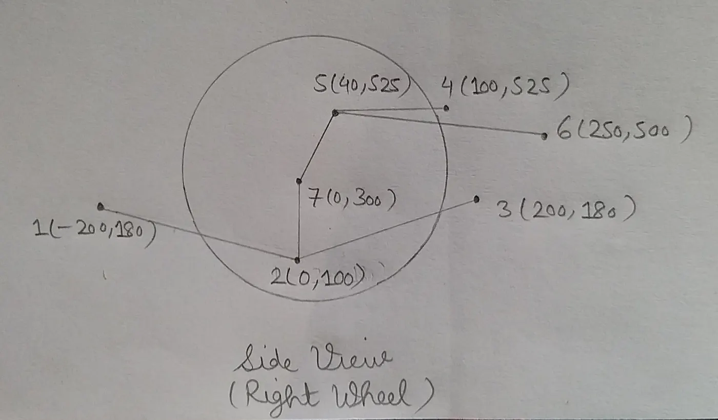 |
|
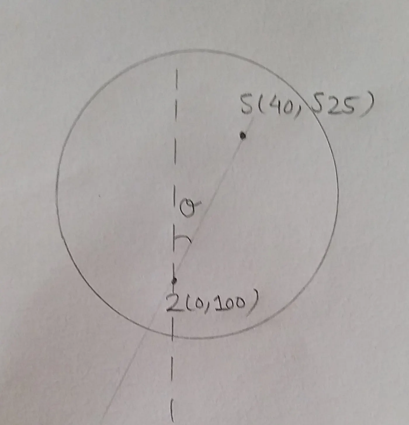
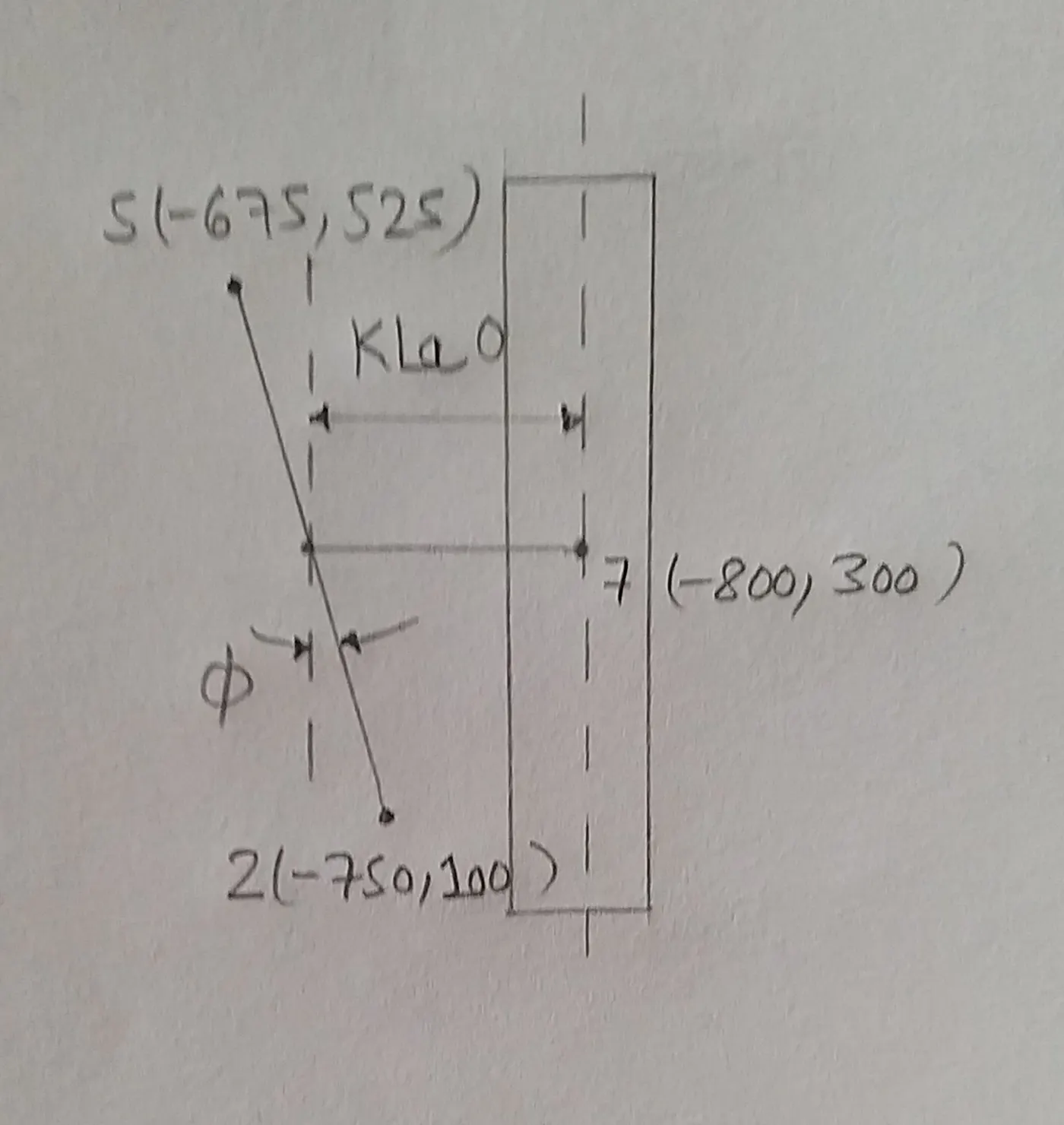
Caster (`theta`) Line 5-2 in Side-View: `theta = tan^-1 (frac[40-0][525-100])` `theta = 5.376^0` |
|
|
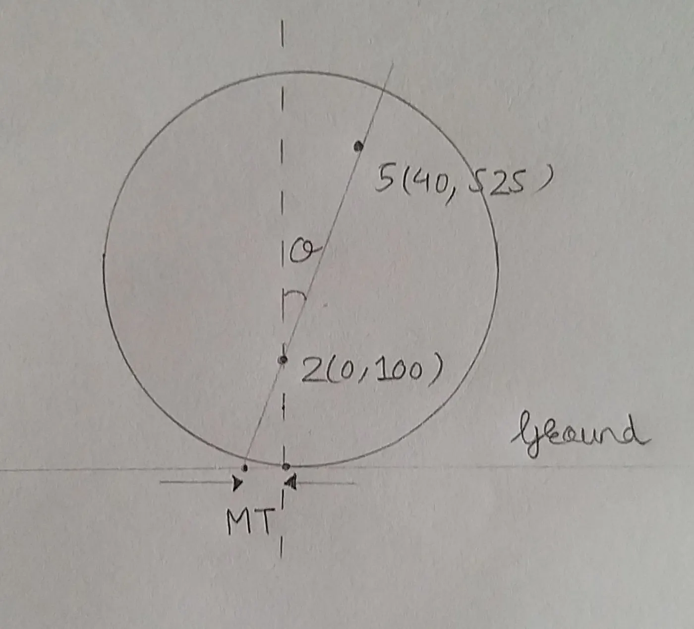
Mechanical Trail (`MT`) Line 5-2 in Side-View: `Slope(m) = frac[525-100][40-0] = 10.625` `z = mx + c rArr 100 = 10.625*0 + c rArr c = 100` At road surface, `z = 0` `0 = 10.625*x + 100 rArr x = - 9.411 mm` `MT = -9.411 mm` Negative sign indicates it is to the left of the vertical Z-axis. |
|
|
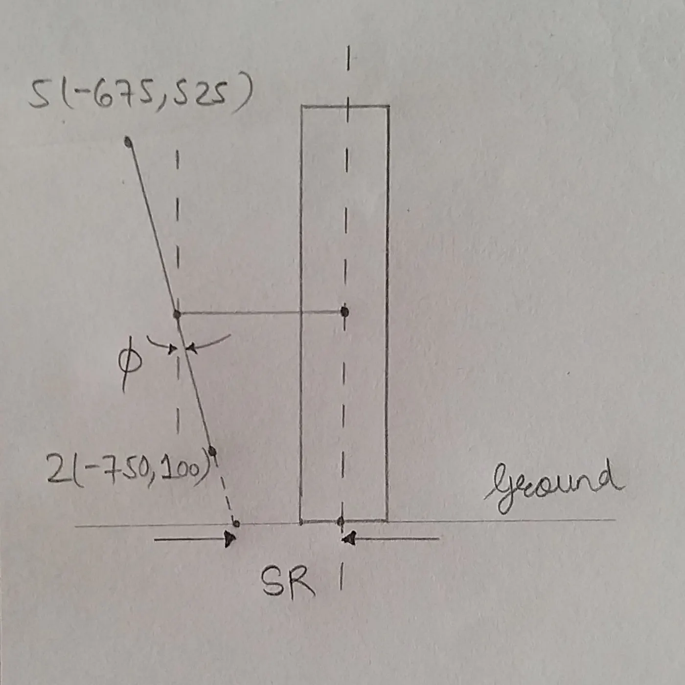
Kingpin Inclination (`phi`) Line 5-2 in Front-View: `phi = tan^-1(frac[-675-(-750)][525-100]) = 10.0079^o` |
|
|
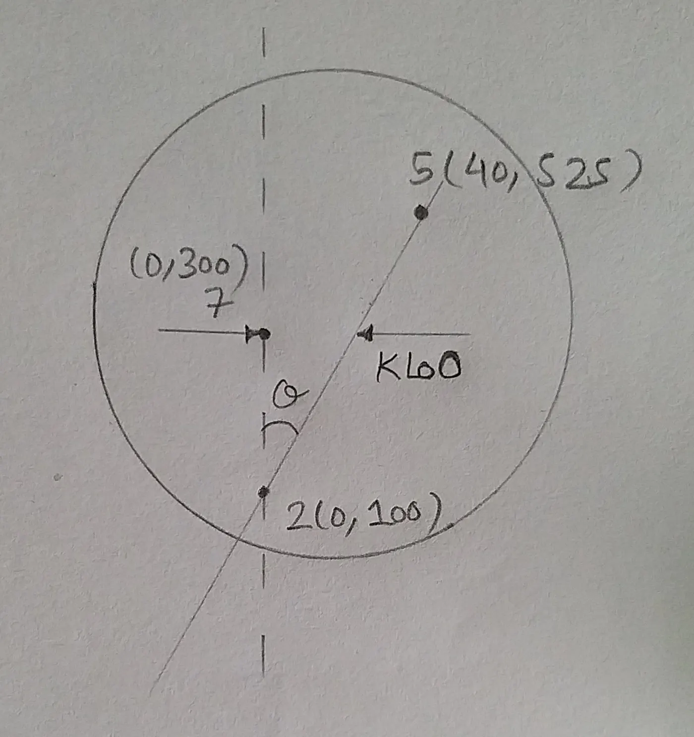
Kingpin Longitudinal Offset (`KLoO`) Line 5-2 in Side-View: `KLoO = (40 - 0) - 225*tan(5.376) = 18.826 mm` |
|
|
Scrub Radius (`SR`) Line 5-2 in Front-View: `Slope(m) = frac[525-100][-675-(-750)] = 5.667` `z = my + c rArr 100 = 5.667*(-750) + c rArr c = 4350.25` At road surface, `z = 0` `0 = 5.667*y + 4350.25 rArr y = - 767.646 mm` `SR = -800 - (-767.646) = -32.354 mm` |
|
|
Kingpin Lateral Offset / Spindle Length (`KLaO`) Line 5-2 in Front-View: `KLaO = (-800 - (-675)) - (-225*tan(10.0079) ) = -85.294 mm` |
|

Excel Output:
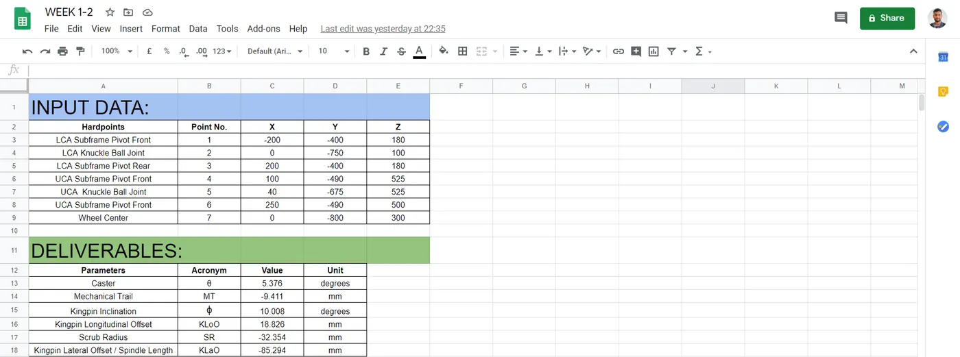
Excel Link: https://docs.google.com/spreadsheets/d/1eFfGHUwRS3SdU_qTGnhZDgpvFyKfgL7fGL-nSH36SzE/edit#gid=0
2. If the pneumatic trail is 25 mm and lateral force is 2000N, Calculate the restoring moment acting at the point where kingpin intersects the ground in side view.
- Lateral Force (`F_y`) = 2000
Pneumatic Trail (`PT`) = 25 mm
Mechanical Trail (`MT`) = 9.411 mm
Restoring Moment = `F_y*(PT+MT) = 2000*(25+9.411) = 68822 N.mm = 68.822 N.m`
3. Suggest a hardpoint recommendation to change the sign of the scrub radius that you calculated.
- Move the UCA Knuckle Ball Joint away from the wheel axis or LCA Knuckle Ball Joint towards the wheel axis so that the slope (tilt) of line 5-2 increases and we obtain an intersection on the other side of the axis.
4. Calculate the following geometric parameters:
(i) Instantaneous centre location (coordinates)
(ii) Roll centre height
GIVEN DATA:
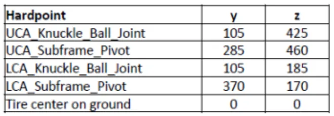
Assume the tire radius to be 300mm and the track to be 1600mm.
SOLUTION:
Geometric Representation:
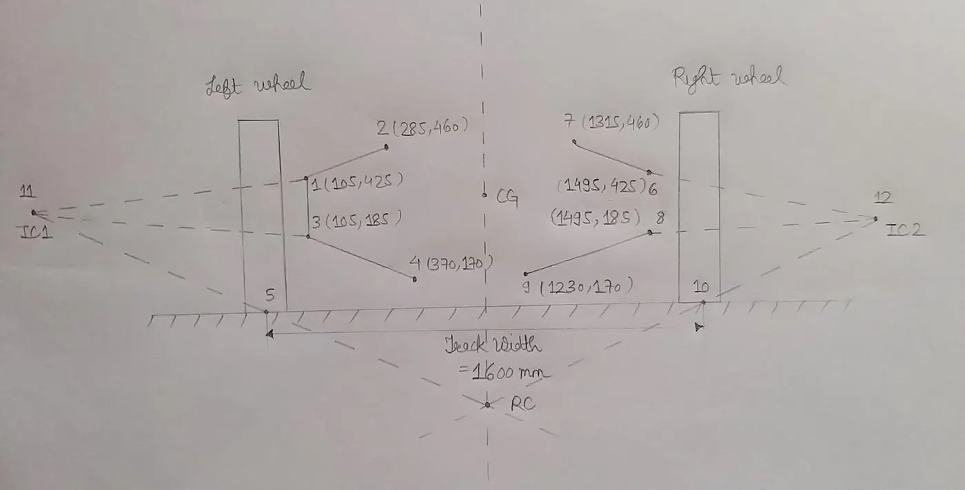
LEFT SIDE:
|
UCA of Left Wheel: Line 1-2 `Slope(m) = frac[460-425][285-105] = 0.1945` `z = my + c rArr 425 = 0.1945*105 + c rArr c = 404.5775` `z = 0.1945y + 404.5775` .... (A) |
LCA of Left Wheel: Line 3-4 `Slope(m) = frac[185-170][105-370] = -0.0566` `z = my + c rArr 185 = -0.0566*105 + c rArr c = 190.943` `z = -0.0566y + 190.943` .... (B) |
|
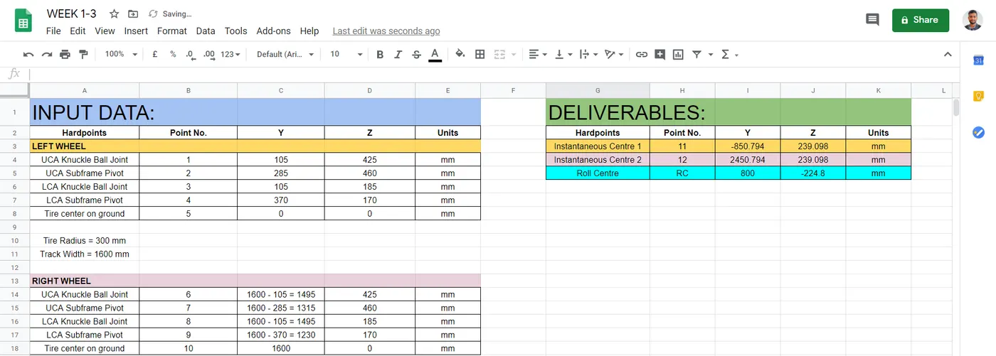
Instantaneous Centre 2 (Left): Solving equations A and B; we get IC Left coordinates `z = 239.098 mm` `y = -850.794 mm` |
IC1 and Tire Center: Line 11-5 `Slope(m) = frac[239.098-0][-850.794-0] = -0.281` `z = my + c rArr 0 = -0.281*0 + c rArr c = 0` `z = -0.281y + 0` .... (C) |
RIGHT SIDE:
|
UCA of Right Wheel: Line 6-7 `Slope(m) = frac[460-425][1315-1495] = -0.1945` `z = my + c rArr 425 = -0.1945*1495 + c rArr c = 715.7775` `z = -0.1945y + 715.7775` .... (D) |
LCA of Right Wheel: Line 8-9 `Slope(m) = frac[185-170][1495-1230] = 0.0566` `z = my + c rArr 185 = 0.0566*1495 + c rArr c = 100.383` `z = 0.0566y + 100.383` .... (E) |
|
Instantaneous Centre 2 (Right): Solving equations D and E; we get IC Right coordinates `z = 239.098 mm` `y = 2450.794 mm` |
IC2 and Tire Center: Line 12-10 `Slope(m) = frac[239.098-0][2450.794-1600] = 0.281` `z = my + c rArr 0 = 0.281*1600 + c rArr c = -449.6` `z = 0.281y - 449.6` .... (F) |
Roll Centre:
Solving equations C and F; we get Roll Centre
`z = - 224.8 mm`
`y = 800 mm`
Roll Centre Height, `RC = 224.8 mm` in downward direction.
Excel Output:
Excel Link: https://docs.google.com/spreadsheets/d/1kkcpjJbORyuMCtr1oc5UbTkA_PErFGRs0T2sDSN3DQ4/edit#gid=0