Spring and Anti-roll bar Selection based on Vehicle Targets for a 4WD Sedan
AIM: To select springs and anti-roll bars, and set up swing arm geometry to meet targets for ride frequency, roll gradient and pitch gradient, while staying within certain constraints.
OBJECTIVE: You are a part of the chassis development team for a 4WD sedan with a McPherson strut suspension in the front and a multilink setup in the rear. The program is in its early stages and you currently need to select baseline springs and anti-roll bars based on some vehicle level targets.
Deliverables:
• Spring rates (front and rear)
• Roll bar diameters (front and rear)
• Rear ride frequency and flat ride plot (at 65 mph)
• Anti characteristics (front and rear - in terms of percentages and instant center locations)
Target values:
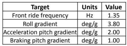

GIVEN DATA:
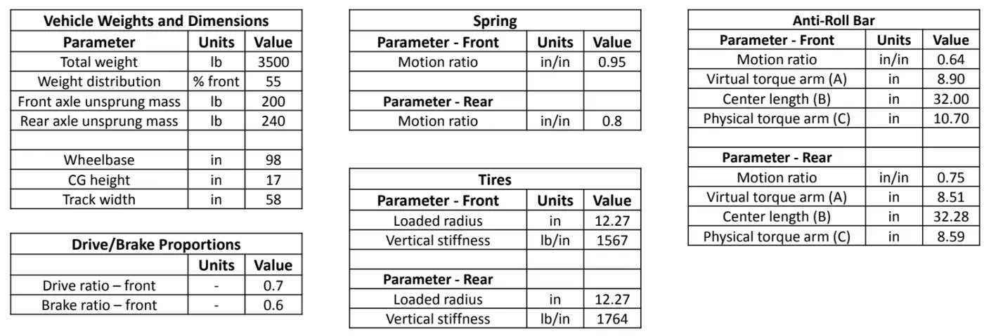
Additional Information and Assumptions:
- You will need to do this project in excel/octave. Excel is preferred. Do not attempt to due it through pen and paper calculations. It will become very tedious. Remember this is an iterative process. For example, spring rates that satisfy one target might not work for the others. You will be going back and forth. So you will need a tool like excel. A good suggestion is to use multiple sheets within a workbook (for ride frequency, pitch and roll).
- The spring rates will have to be reported in lb/in, roll bar diameter in mm, ride frequency in Hz and swing arm height/length in inches.
- Assume that spring rates and roll bar diameters are available only in increments of 0.25. So select the best available options. For example, if you calculate spring rate to be 125.67 lb/in, you will report 125.75 lb/in.
- Assume the roll bar to be solid (inner diameter = 0).
- We want a 5% higher load transfer in the front to get understeer. So if you get x lb/g of load transfer in the front, add 5% of the total load transfer to this number to get the desired front load transfer.
- A 5% deviation in all targets is allowed.
- The percentages of anti characteristics cannot be negative or greater than 100.
- For swing arm horizontal distance, 70 to 120 inches is a reasonable starting point. From there on, optimize for pitch gradients.
- A diagram in the side view showing sprung CG location, roll center location, sprung mass roll moment arm, etc. would be valuable.
SOLUTION:
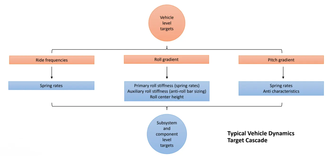
A typical Vehicle Dynamics Target Cascade is shown below which depicts the workflow of our problem.
Stage I: Ride analysis
The aim of this stage is to calculate the ride frequencies (front and rear) based on the wheelbase and speed of the vehicle. Using this, the ride rates, wheel rates and ultimately the spring rates were found out.
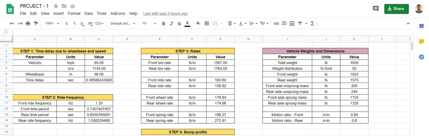
STEP 1: Time delay due to wheelbase and speed
The time lag (time delay) resulting in the hitting of front and rear wheels to the bump results in an out of phase motion. This is called as Pitching motion.
Time delay (sec) is given by:
`t_d = frac(WB)(v)`
where;
`WB` = wheelbase (in)
`v` = velocity (in/sec)
STEP 2: Ride frequency
A ride frequency is the undamped natural frequency of the body in ride. The higher the frequency, the stiffer the ride. So, this parameter can be viewed as normalized ride stiffness. If the frequency is less, the stiffness is less that provides comfort and usually found in passenger vehicles.
Ride frequencies for different vehicle classes are as follows:
Passenger cars - 0.5 to 1.5 Hz
Sedan cars - 1.5 to 2 Hz
Race cars - 3 to 5 Hz
Front time period (sec) is given by:
`t_f = frac(1)(f_f)`
Rear time period (sec) is given by:
`t_d = t_f - t_r rArr t_r = t_f - t_d`
Rear ride frequency (Hz) is given by:
`f_r = frac(1)(t_r)`
Rear frequency should be higher than the front frequency so that the rear suspension catches up with the front suspension and a Flat Ride condition is maintained. This means that the rear amplitude catches up with the front amplitude at a particular instant.
Rear frequency is almost 1.13 times the front frequency.
STEP 3: Determining the rates
Ride rate is defined as vertical force per unit vertical displacement of the tire ground contact with respect to chassis.
Ride rate (lb/in) is given by:
`f = frac(1)(2 pi) sqrtfrac(k_r)(m_s)`
`k_r = frac(4 pi^2 f^2 m_s)(386.4)`
where;
`f` = Ride frequency (Hz)
`m_s` = Sprung mass per corner (lb)
386.4 = Conversion factor from N/m to lb/in considering mass in lb
Wheel rate is a measure of the effective stiffness of the suspension system measured at the wheel center.
Wheel rate (lb/in) is given by:
`k_w = frac(k_t . k_r)(k_t - k_r)`
where;
`k_r` = Ride rate (lb/in)
`k_t` = Tire rate (lb/in)
Spring rate refers to the amount of weight that is needed to compress a spring by one inch.
Spring rate (lb/in) is given by:
`k_w = k_s . MR^2 rArr k_s = frac(k_w)(MR^2)`
where;
`k_s` = Spring rate (lb/in)
`MR` = Motion ratio (in/in)
STEP 4: Bump Oscillation profile
An accurate representation of the pitching can be made using a Bump Oscillation profile. To construct this, we need the front and rear amplitudes and they are given by:
`A_f = e^(-t) sin(2 pi f_f t)`
`A_r = e^(-t) sin(2 pi f_r (t - t_d))`
where;
`A_f` = Front amplitude (in)
`A_r` = Rear amplitude (in)
`f_f` = Front ride frequency (Hz)
`f_r` = Ride ride frequency (Hz)
`t` = Time at a particular instance (sec)
`t_d` = Time delay (sec)
Code: A MATLAB program to plot a Bump Oscillation profile for Flat Ride condition is shown below.
% Bump Oscillation profile.

% Inputs:

Ws_front = 1725; Ws_rear = 1335;  % Sprung mass (lb/corner)
Wus_front = 200; Wus_rear = 240;  % Unsprung mass (lb/corner)

kt_front = 1567; kt_rear = 1764;  % Tire rate (lb/in)
kw_front = 178.94; kw_rear = 174.66;  % Wheel rate (lb/in)
kr_front = 160.6; kr_rear = 158.92;   % Ride rate (lb/in)

t_d = 0.08566433566;   % Time Delay (sec)


% Solution:

fs_front = sqrt(kr_front*1000/Ws_front)/(2*pi);  % Sprung mass frequency (Hz)
fs_rear = sqrt(kr_rear*1000/Ws_rear)/(2*pi);

fus_front = sqrt((kt_front + kw_front)*1000/Wus_front)/(2*pi);  % Unsprung mass frequency (Hz)
fus_rear = sqrt((kt_rear + kw_rear)*1000/Wus_rear)/(2*pi);

time = linspace(0,3.5,350);  % Time period

for i = 1:length(time)
    amp_s_front(i) = exp(-time(i))*sin(2*pi*fs_front.*time(i));
    amp_s_rear(i) = exp(-time(i))*sin(2*pi*fs_rear.*(time(i)-t_d));
    amp_us_front(i) = exp(-time(i))*sin(2*pi*fus_front.*time(i));
    amp_us_rear(i) = exp(-time(i))*sin(2*pi*fus_rear.*(time(i)-t_d));
end


% Plot:

subplot(2,1,1)
plot(time,amp_s_front,'linewidth',3);
hold on
plot(time,amp_s_rear,'linewidth',3);
title('Bump Oscillation (Sprung)')
xlabel('Time (sec)')
ylabel('Amplitude (in)')
grid on

subplot(2,1,2)
plot(time,amp_us_front,'linewidth',3);
hold on
plot(time,amp_us_rear,'linewidth',3);
title('Bump Oscillation (Unsprung)')
xlabel('Time (sec)')
ylabel('Amplitude (in)')
grid on
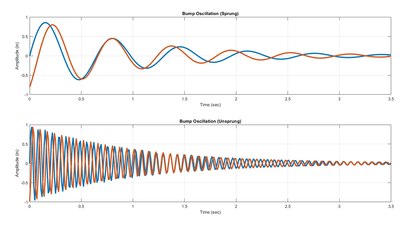
Plot: After a span of 0.5 secs, the amplitudes match. Usually, beyond one complete cycle i.e. 1 sec, the amplitude reduces and the damper takes care to nullify the remaining oscillations thus eliminating the pitching.
Stage II: Roll analysis
The aim of this stage is to calculate the roll stiffness contribution in the front and rear which keeping the given roll gradient within the specified limits.
The auxiliary roll stiffness also needs to be constrained within a certain mark for which the spring rates play a primary role. This is used to determine the primary roll stiffness. If they are beyond the prescribed limits, the spring rates are altered (by an increment/decrement of 0.25 lb/in). During this process, make sure that the front ride frequency is within 5% tolerance of the suggested value.
After this, the roll bar is designed in compliance with the target roll gradient. An appropriate anti-roll bar selection must be done in order to avoid the roll.
|
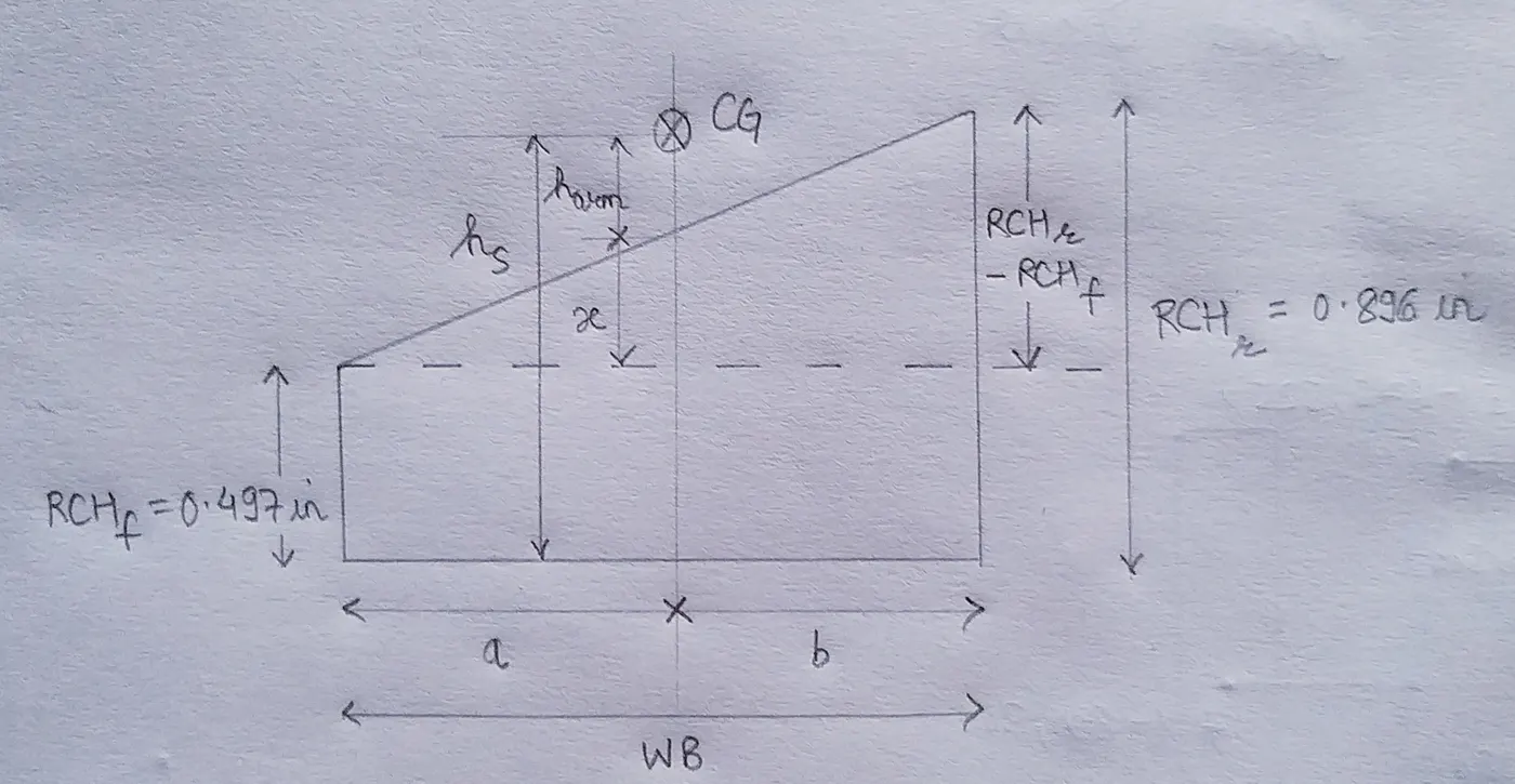
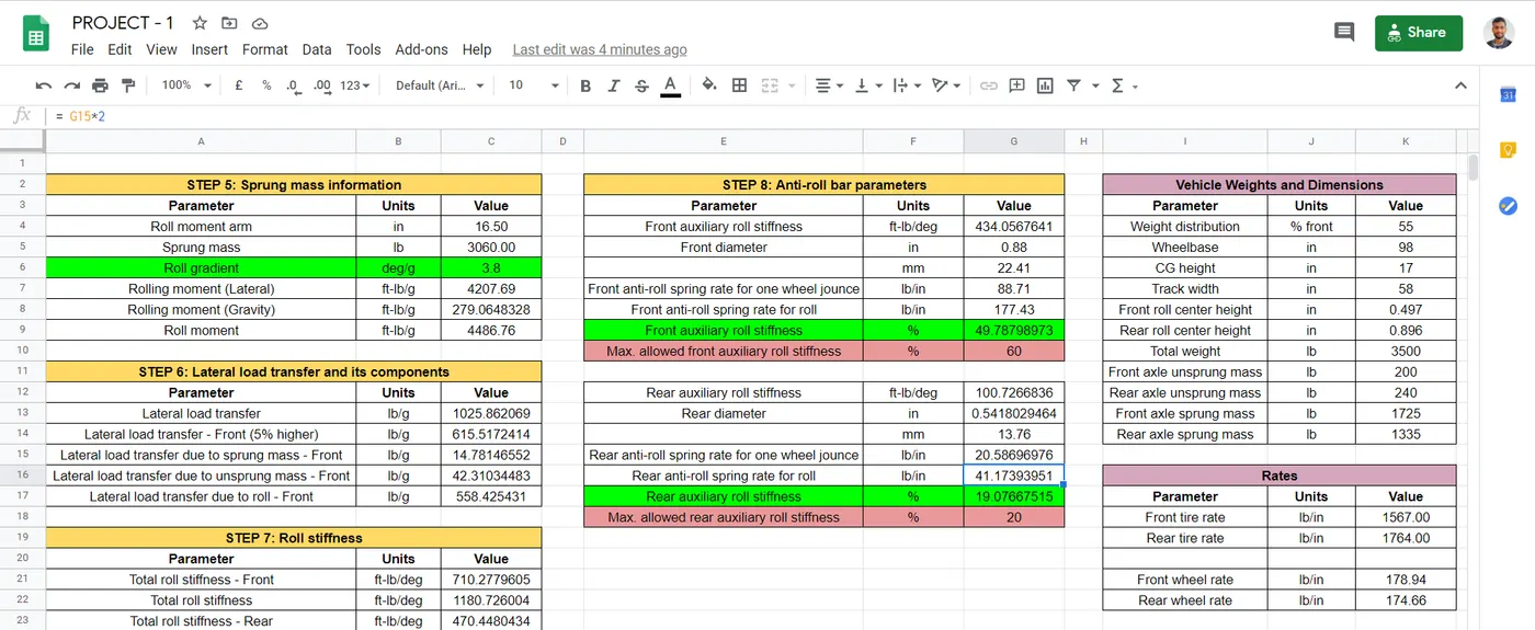
STEP 5: Sprung mass information The height of roll moment arm (in) is given by: `h_(arm) = h - frac(RCH_f . b + RCH_r . a)(WB)` where; `h` = CG height (in) `RCH_f` = Front roll center height (in) `RCH_r` = Rear roll center height (in) `a` = Distance between front roll center and CG (in) = `frac(W_f . WB)(W)` `b` = Distance between rear roll center and CG (in) = `frac(W_r . WB)(W)` Roll moment that tends to cause a vehicle to roll, that is to rotate about its longitudinal axis. Roll moment (ft-lb/g) is given by: `M_(phi Lateral) = m_s . h_(arm)` ... (Lateral component) `M_(phi Gravity) = m_s . h_(arm) . frac(phi)(A_y) . frac(pi)(180)` ... (Gravity component) `M_(phi) = M_(phi Lateral) + M_(phi Gravity)` where; `M_(phi)` = Roll moment (ft-lb/g) `frac(phi)(A_y)` = Roll gradient (deg/g) |
|
|
STEP 6: Lateral load transfer and its components Lateral load transfer occurs during cornering and is the shift of mass across the wheels due to the centrifugal force and the lateral acceleration. Lateral load transfer (lb/g) is given by: `LT_(Lateral) = frac(W . h)(TW)` where; `W` = Total weight (lb) `TW` = Track width (in) In order to achieve the understeer effect, the load transfer at front needs to be higher than rear. Usually, 5% margin can suffice this requirement. `LT_f = LT_(Lateral) . frac(% Front + 5)(100)` `LT_s = frac(W_s . RCH)(TW)` `LT_(us) = frac(W_(us) . R_t)(TW)` where; `W_s` = Sprung mass (lb) `W_(us)` = Unsprung mass (lb) `R_t` = Tire radius (in) |
|
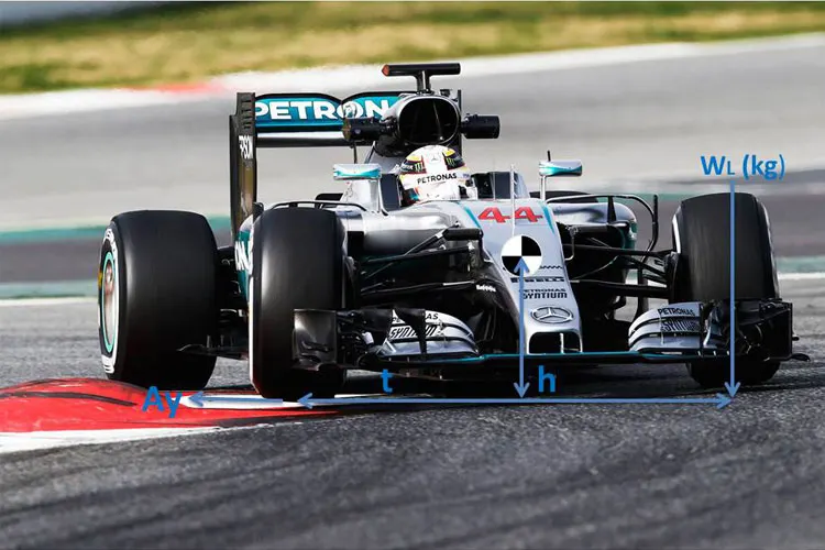
To compute lateral load transfer due to roll, we need to exclude the effects arising due to sprung and unsprung mass.
`LT_(phi) = LT_f - LT_s - LT_[us]`
STEP 7: Roll stiffness
Roll stiffness is the torque on the chassis to cause a certain roll angle.
|
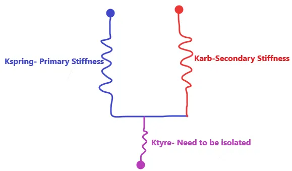
Roll stiffness at the front is given by: `k_(phif) = frac(LT_(phi))(phi)` Total roll stiffness is given by: `k_(phi) = frac(M_(phi))(phi)` Roll stiffness at the rear is given by: `k_(phir) = k_(phi) - k_(phif)` Roll stiffness due to tire rate is given by: `k_(phit) = k_t . frac(TW^2)(2)` Roll stiffness due to wheel rate is given by: `k_(phiw) = k_w . frac(TW^2)(2)` Roll stiffness at wheel center level is given by: `k_(phiWC) = frac(k_(phit) . k_(phi))(k_(phit) - k_(phi))` Auxiliary roll stiffness is given by: `k_(phiarb) = k_(phiWC) - k_(phiw)` |
 |
STEP 8: Anti-roll bar parameters
An anti-roll bar (roll bar, anti-sway bar, sway bar, stabilizer bar) is a part of automotive suspensions that helps reduce the body roll of a vehicle during fast cornering or over road irregularities. It connects opposite (left/right) wheels together through short lever arms linked by a torsion spring.
The stiffness of solid anti-roll bar is given by Fred Puhn's Sway Bar relation:
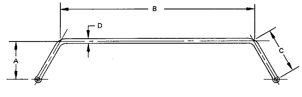
`k_(arb) = frac(500000 . D_o^4)(0.4422 . A^2 B + 0.2264 . C^3)`
Anti-roll spring rate for one wheel jounce = `frac(500000 . (D_o^4 - D_i^4))(0.4422 . A^2 B + 0.2264 . C^3) . MR^2 . frac(TW^2)(2)`
|
where; `D_o` = Outer diameter (in) `D_i` = Inner diameter (in) = 0 ... (For solid bar) `A` = Virtual torque arm (in) `B` = Center length (in) `C` = Physical torque arm (in) |
 |
Anti-roll spring rate for roll = `2 . k_(arb)`
Auxiliary roll stiffness = `frac(k_(aux))(k_(WC)`
where;
`k_(aux)` = Auxiliary roll stiffness (ft-lb/deg)
`k_(WC)` = Roll stiffness at wheel center level (ft-lb/deg)
Stage III: Pitch analysis
The aim of this stage is to calculate the pitch parameters during acceleration and braking while keeping the given pitch gradient within the specified limits.
Pitching is the shift in vehicle weight forward or backward due to acceleration or braking due to the longitudinal load transfer.
|
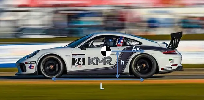
STEP 9: Longitudinal load transfer and its components When a car is accelerating or braking, a reaction force is generated similar to the centrifugal force generated when cornering. Longitudinal load transfer (lb/g) is given by: `LT_(Longitudi nal) = frac(W . h)(WB)` where; `W` = Total weight (lb) `WB` = Wheelbase (in) |
 |
STEP 10: Deflection and Pitch angle
Deflection is given by:
`z = frac(LT_(Longitudi nal))(2 . k_w)`
Pitch angle is the angle of the vehicle body that it makes with the horizontal in the longitudinal direction.
Pitch angle is given by:
`theta = tan^-1(frac(z_f + z_r)(WB))`
STEP 11: Swing arm geometry
The instantaneous center lengths from the contact patch are altered and tuned to optimize he pitch gradient as per the target value. They are as follows:
Front IC Vertical distance = 12.3 in
Front IC Horizontal distance = 70 in
Rear IC Vertical distance = 12.5 in
Rear IC Horizontal distance = 73 in
STEP 12: Pitch analysis - Acceleration
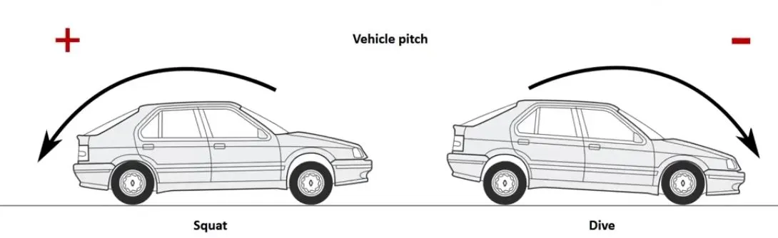
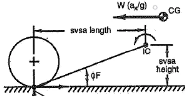
Anti characteristics can be defined as a geometry used to eliminate the deflection caused due to load transfer with the help of horizontal forces.
|
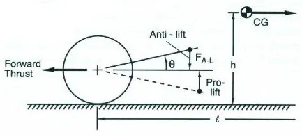
Anti-lift is the reduction of rebound effect in the front suspension during acceleration and rear suspension during braking. Front anti-lift angle is given by: `theta_(AL) = tan^-1(frac(FV_(IC) - R_t)(FH_(IC)))` |
 |
|
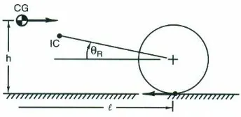
Anti-squat is the reduction in compressive effect in the rear suspension during braking. Rear anti-squat is given by: `theta_(AS) = tan^-1(frac(RV_(IC) - R_t)(RH_(IC)))` |
 |
|
Swing arm angle is given by: `theta_(S) = tan^-1(frac(h)(WB))` where; `FV_(IC)` = Front IC vertical distance from contact patch (in) `FH_(IC)` = Front IC horizontal distance from contact patch (in) `RV_(IC)` = Rear IC vertical distance from contact patch (in) `RH_(IC)` = Rear IC horizontal distance from contact patch (in) |
 |
The fraction of anti-characrteristics during acceleration is given by:
`Anti-li ft % = frac(theta_(AL) . phi_d . 100)(theta_S)`
`Anti-squat % = frac(theta_(AS) . (1 - phi_d) . 100)(theta_S)`
where;
`phi_d` = Drive ratio
STEP 13: Pitch analysis - Braking
Front anti-dive angle is given by:
`theta_(AD) = tan^-1(frac(FV_(IC))(FH_(IC)))`
Rear anti-squat angle is given by:
`theta_(AS) = tan^-1(frac(RV_(IC))(RH_(IC)))`
The fraction of anti-characrteristics during braking is given by:
`Anti-d ive % = frac(theta_(AD) . phi_b . 100)(theta_S)`
`Anti-squat % = frac(theta_(AS) . (1 - phi_b) . 100)(theta_S)`
where;
`phi_b` = Brake ratio
Deflection with compensation is given by:
`z_(pc) = z . frac(100 - Anti-li ft %)(100)`
Excel Output:
Inputs and Targets:

Ride analysis:
Roll analysis:
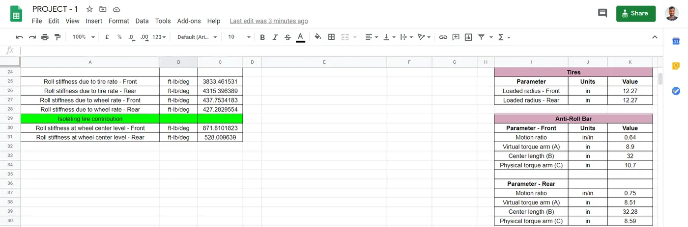
Pitch analysis:
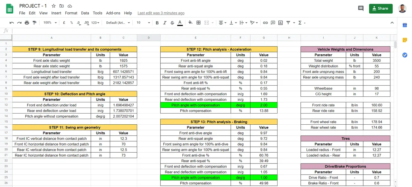
Excel Link: https://docs.google.com/spreadsheets/d/1VXaCrOOMixlEECnb_Vwk8DPFW0ItASftK6l-NXsYNh4/edit#gid=2040716608
CONCLUSION: The spring and anti-roll bar parameters were selected to achieve the following targets;
| Spring rate |
Front: 198.27 lb/in Standard: 198.25 lb/in |
Rear: 272.91 lb/in Standard: 273.00 lb/in |
| Anti-roll bar diameter | Front: 0.88 mm | Rear: 0.54 mm |
| Auxiliary roll stiffness |
Front: 49.78 % Allowed: 60 % |
Rear: 19.07 % Allowed: 20 % |
| Pitch gradient | Acceleration: 2.00 deg/g | Braking: 1.00 deg/g |
REFERENCES:
1. Race Car Vehicle Dynamics by William F Milliken
2. Fundamentals of Vehicle Dynamics by Thomas D Gillespie