SOLID MESHING
TITLE: Solid meshing of Rear view mirror component.
SUMMARY: A vehicle's rear view mirror component is consider here, we perform a solid meshing on it. Initially the solid geometry is consider, which is checked and certain errors, abnormalities are fixed followed by its mesh execution. Here, after regular mesh execution we deployed a volume mesh on given component which allows to fill the gap between unmesh closed volume space with unstructued 3D elemental type. Followed by checking quality criteria such as Max, Min length for 2D elements while Tet collapse for 3D elements.
INTRODUCTION: Generally,a rear-view mirror is a flat mirror in automobiles and other vehicles, designed to allow the driver to see rearward. Here, we are suppose to mesh its geometry using solid meshing method. The solid meshing itself allow to mesh the entire component without taking any mid surface. Later Volume Mesh methodology allows to fill the empty gaps between the component's surface with unstructured 3D elements. The Tetra Rapid algorithm is used later to do so.
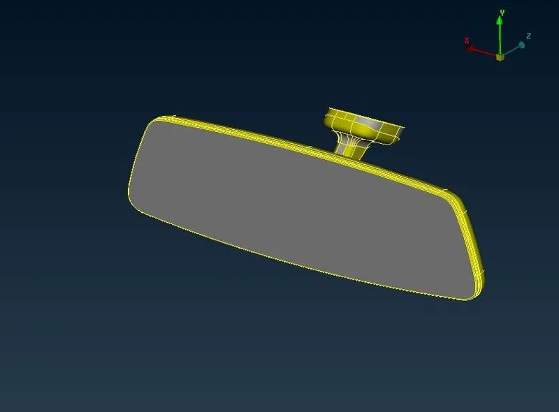 Fig 1.1 Rear View Mirror
PROCEDURES:
- The rear view mirror solid geometry is execute under geometry check manager for any triple cons, cracks or other unwanted abnormalities and are later fixed.
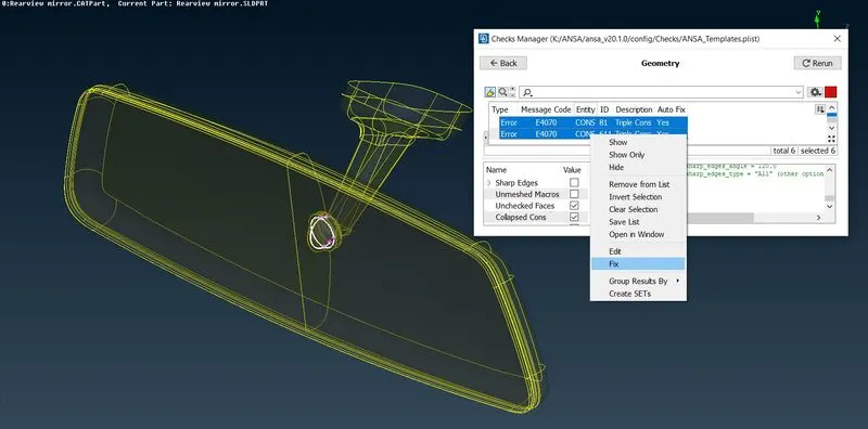 Fig 1.2 Check Manager
- The model under mesh module is provided length for both perimeter and macros as 1mm each in order to get fine visibility purpose.
- First things first, we assign the required quality criteria values which are as follows,
S.No Quality Criteria Values 1 Target/Average length 1 2 Minimum Length 0.5 3 Maximum Length 2 4 Tet collapse 0.2 - Here, we gonna be checking the quality for 2D elements are its minimum and maximum length while, tet collapse error for 3D elements only.
- Our aim is to mesh the features containing parts using ortho-tria mesh however, its has more feature capturing ability. Meanwhile the normal parts or features excluding parts can be meshed using regular tri mesh methodology. Both can be used and deploy manually.
- Now, geometric model is meshed using Batch mesh manager module. The Batch mesh manager itself allow the geometry to execute proper as well as desired mesh followed by performing deafeaturing by itself. Batch mesh executes proper mesh along with required defeaturing methodology which results is good feature capturing ability.
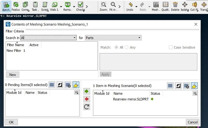 Fig. 1.3 Batch Mesh Execution
- Now Batch Mesh is deployed, we can use its ability of defeaturing in order to get more desired mesh flow on complex, feature containing parts without any kinks and dips.
- Here, we erase the batch mesh and manually deployed ortho-tria mesh on features and tria mesh on regular parts.
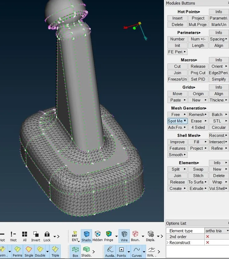
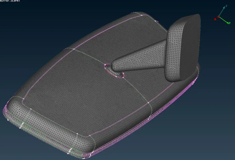 FIG 1.5 Ortho-tria mesh
- We perform Spot mesh module button under mesh module which deploys manually either tria elements or orth tria elements as per requirements. Since the ortho tria mesh captures feature more precisely so,we execute , followed by tria mesh on remaining parts. One can always use reconstruction option if error occurs, it can overcome or can be used other methodology such as moving grids to clear quality
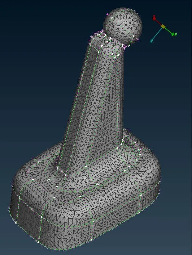
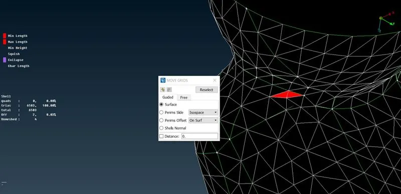 FIG.1.6. Mesh execution & Quality resolving
- We assign PID as PSolid for individual part as per required.
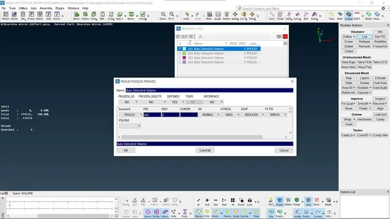 FIG. 1.7 PID
- By Performing these procedures we were able to deploy a full mesh containing both ortho-tria as well as trias elements. Once the meshing is fully executed and deployed, we can switch to Volume mesh module to fill the elements inside the closed volume.We do so, by defining the closed volume in it by simply selecting the part, the ANSA will auto detect volume and later once detected it will visible an unmesh warning on GUI, then we perform remesh using Tetra Rapid method. This allow us to capture a solid meshed geometry which are mostly arranged in an unstructured elemental type.
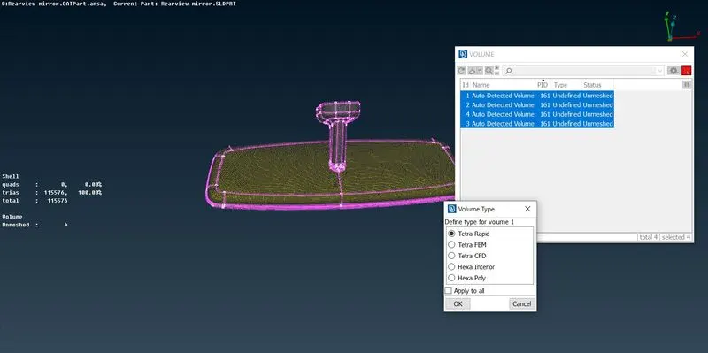 FIG.1.7 Volume Mesh
- Execution of Tetra Rapid takes a bit of time, basically it mesh the closed empty volume with unstructured 3D elements. Once deployed, if we cut its cross section the solid geomtry along with unstructured mesh can be visualize.
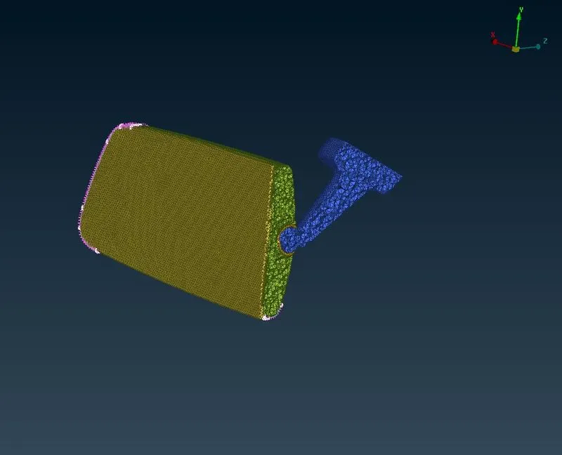 FIG.1.8 Unstructured Mesh
- We switch to Bounds module to control visibility of geometry. The meshed model is free from errors, off elements collapse .
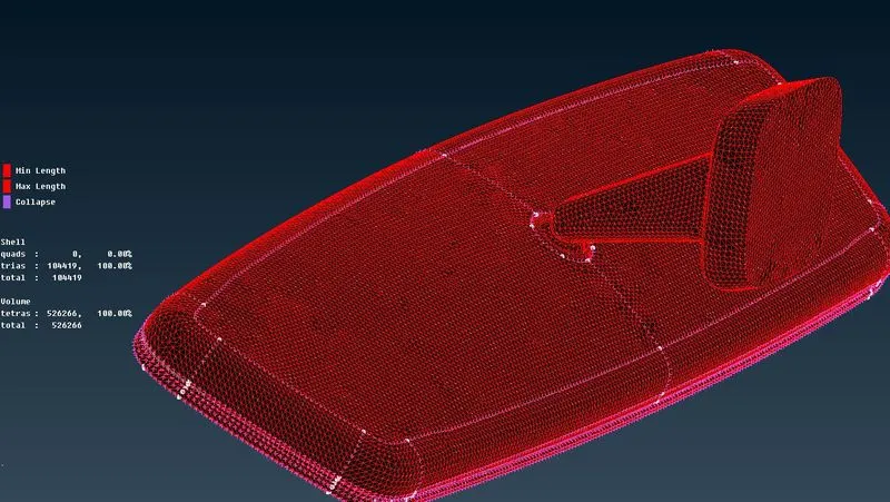 FIG.1.9 Bounds Visibility
CONCLUSION:
Rear View Mirror is Meshed using solid meshing methodology. The desired mesh executed well with good mesh flow. The closed volume is filled with unstructured 3D elements, many of them follows a structured path upto two rows however, once they overcome the second row they do follow unstructured pattern flow.
LEARNING OUTCOMES:
- Batch mesh allows to deploy a good mesh flow, followed by defeaturing capabilities in order to capture more features.
- Defeaturing methodology deployed by batch mesh can be used as an alternative to execute individual's desired mesh flow more precisely with more feature capturing ability
- Volume mesh allows to execute a auto detected closed volume which can be later mesh using Tetra FEM, Tetra Rapid algorithm.
- Clearing quality issues.
- Able to deployed the required type of mesh elements on features or non-featuere parts.