Sketch-Base Features and Dess-Up Feature in Catia.
Objective:- To create a 3D part model using Sketch-Based Features and the Dress-Up Features in CatiaV5 software.
Procedure:-
Open CatiaV5 Software and go to file-New-Part.
Create a point at the center axis with coordinates x=0, y=0, and z=0.
Go to Toolbar-Insert-Sketcher-Positioned sketch.
In Sketcher Positioning select yz-plane and in the projecting point select the center point of the origin.
Sketch the geometry with the Profile toolbar.
Exit the sketch workbench and go to sketch-based Features.
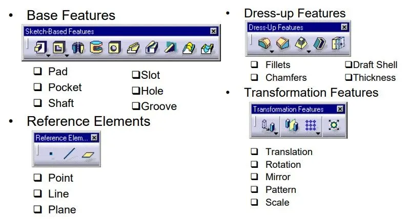
Sketch-Based Features:-
- Rib
- Slot
- Stiffener
- Solid Combine
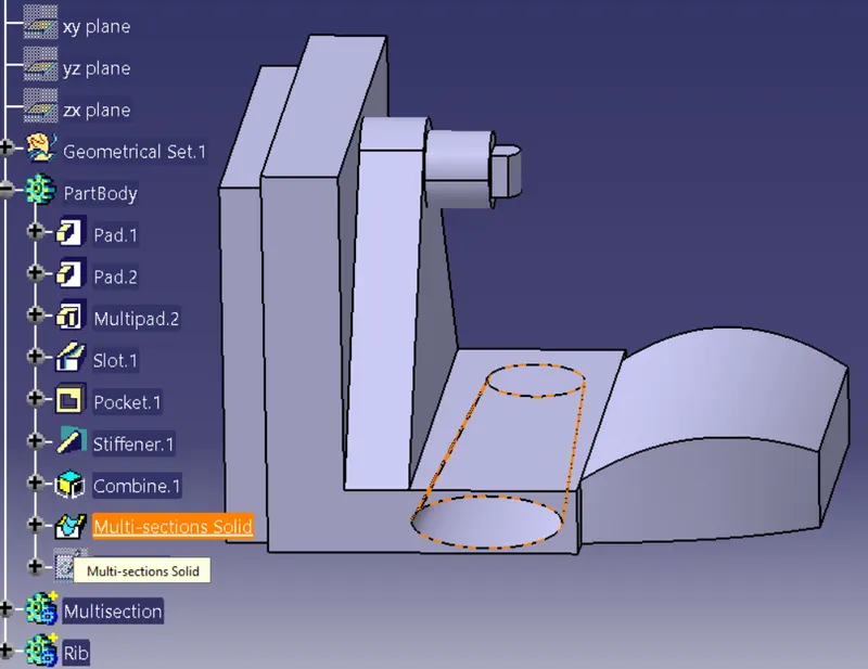
- Multi-Section Solid
- Remove Multi-Section
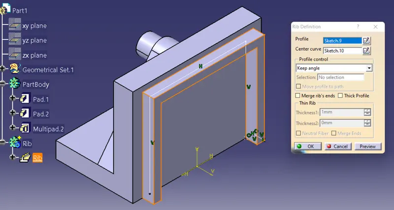
Rib:-
The rib sweep a profile along a center curve to create material. To define a rib, you need a center curve, a planar profile, and possibly a reference element or a pulling direction. To create ribs you can combine the different elements. 3D center curves must be continuous in tangency. If the center curve is planar, it can be discontinuous in tangency.
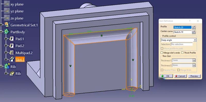
Slot:-
The Slot sweeps a profile along a center curve to remove material. To define a slot, you need a center curve, a planar profile, a reference element, and optionally a pulling direction. To create slots you can combine the different elements.
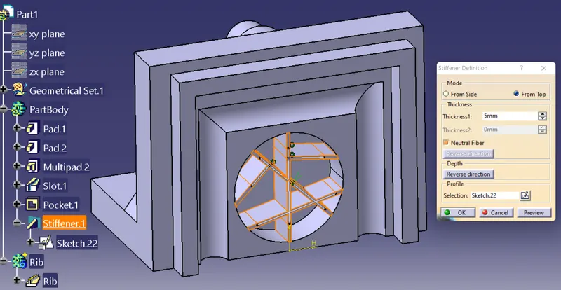
Stiffener:-
Stiffeners are the members which are connected to the thin webs to prevent loss of strength due to web buckling. Stiffeners are added to something in order to stiffen it, such as a support beam, or starch for a collar.
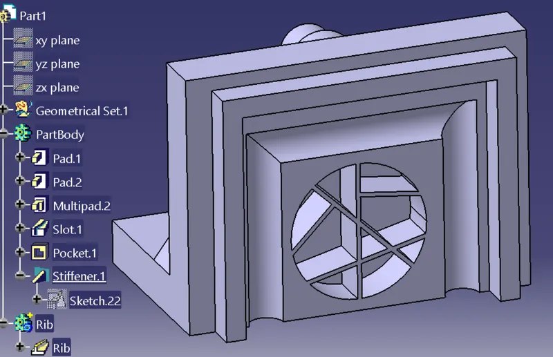
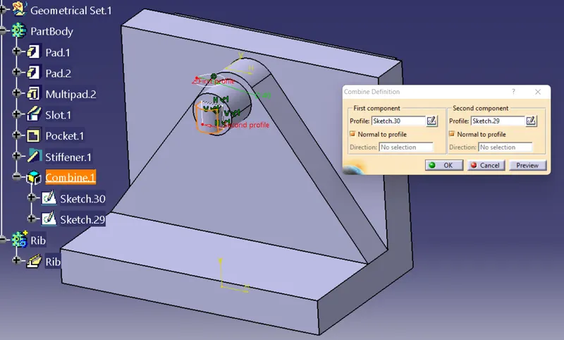
Solid Combine:-
The Solid Combine capability computes the intersection between the profiles virtually extruded. By default, each component is extruded in a plane normal to its sketch plane. There are certain times whereby we need to create a model that involves geometry that has a certain shape that can be divided into two specific views.
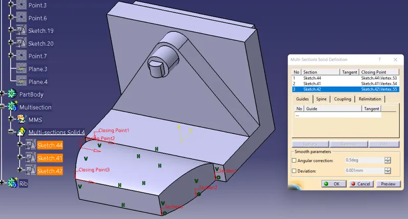
Multi-Section Solid:-
Multi-Section Solid can be generated by sweeping one or more planar section curves along a computed or user-defined spline. The feature can be made to respect one or more guide curves.
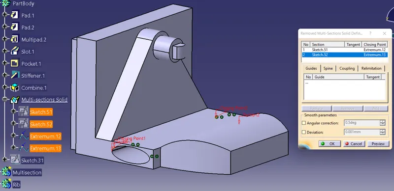
Remove Multi-Section:-
The Remove Multi-sections Solid capability generates lofted material solid by sweeping one or several planar section curves along a computed or user-defined spine then removes this material. The material can be made to respect one or more guide curves.
Dress-Up Features:-
- Thickness
- Edge Fillet
- Variable Fillet
- Face-Face Fillet
- Tritangent Fillet
Thickness:-
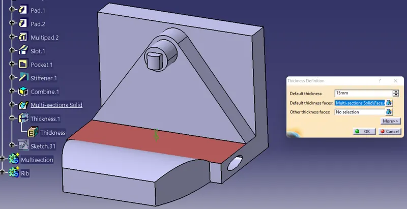
Sometimes, some thicknesses have to be added or removed before machining the part. This feature will add as well as remove the thickness from the surface.
Edge Fillet:-
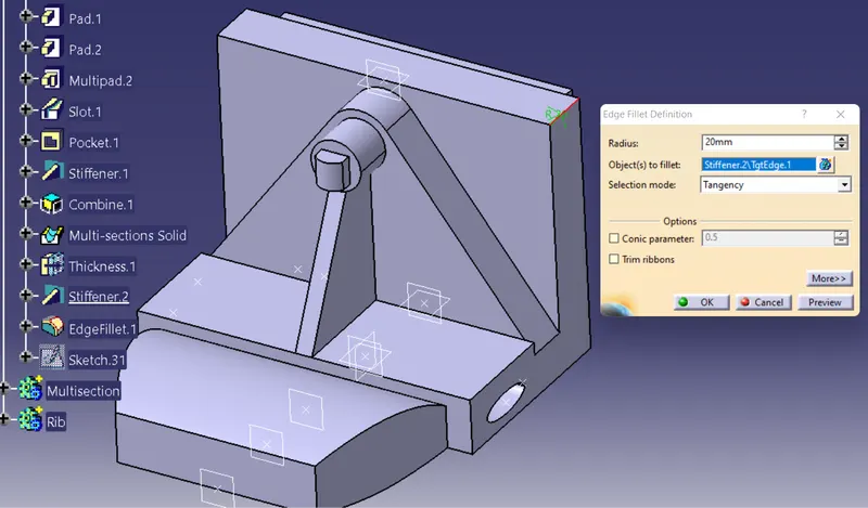
Edge fillets are smooth transitional surfaces between two adjacent faces. Together, these three surfaces form either an inside corner or an outside corner.
Variable Fillet:-
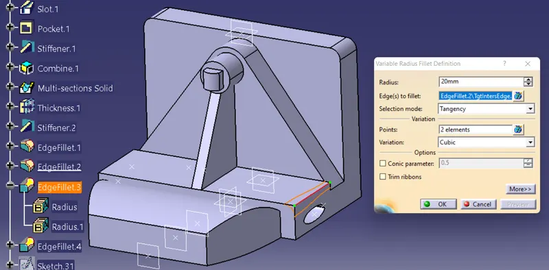
Variable radius fillets are curved surfaces defined according to a variable radius. A variable radius corner means that at least two different constant radii are applied to two entire edges.
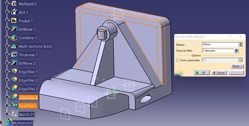
Face-Face Fillet:-
The Face-Face Fillet command is used when there is no intersection between the faces or when there are more than two sharp edges between the faces.
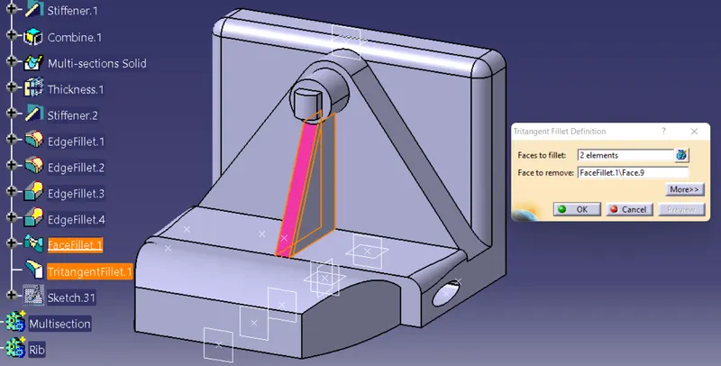
Tritangent Fillet:-
The creation of tritangent fillets involves the removal of one of the three faces selected, as the fillet surface is obtained by rolling a sphere, whose radius is automatically computed to be tangent to the removed surface, between the selected surfaces.
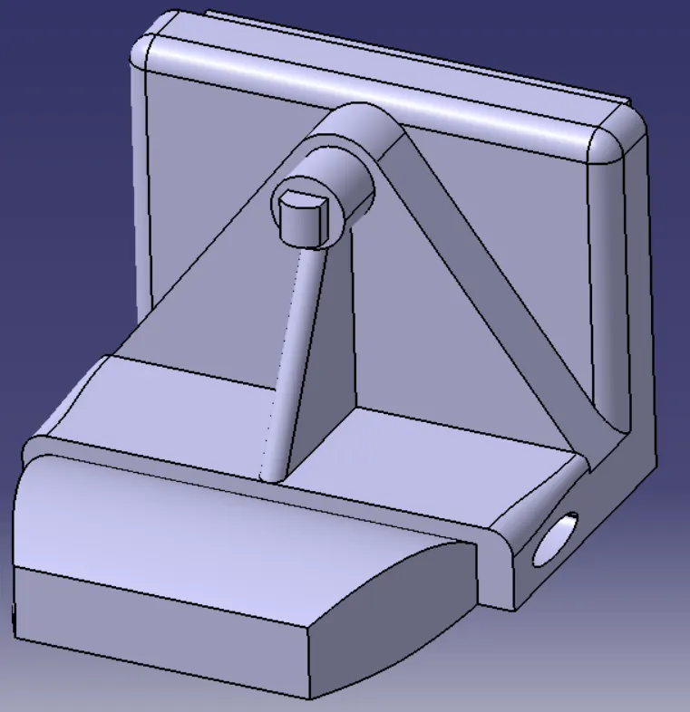
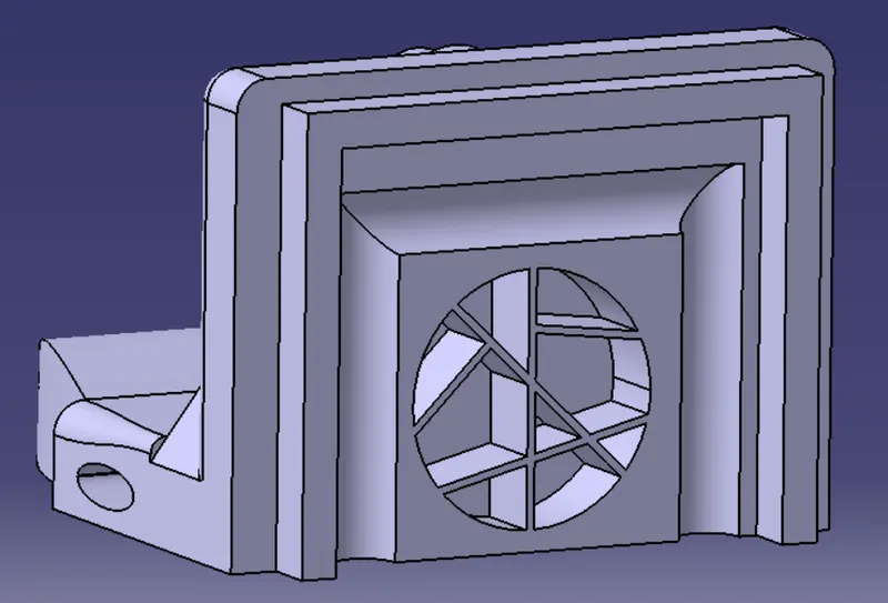
Final PART Model:-
Conclusion:
Hence, we have studied to create a 3D part modeling using the Sketch-Based Features and the Dress-Up Features.
- Vinaykumar Ambadapudithere is a mistake in the process