Sketch a G+1 residential plan according to Vaastu Shastra and Calculation of Loads as per IS code
Ans:Aim : To Sketch a G+1 residential building
Introduction :
Different types of drawings is used in construction such as architectural drawings, structural, electrical, plumbing and finishing drawings. These drawings provides layout plans and details for construction of each and every part of the building. Drawings plays an important role in the construction field to convey the ideologies and perspective of the designer to the layman at site. The drawings may be used to indicate the overall appearance, inside or outside the structure, or they may be used to indicate precise measurements and other details for construction
Types of Construction Drawings
1. Architectural Drawing
1.1 Site Plan
This is primary drawing used for marking out the plan on the ground. It represents the location, orientation and information about the site’s topography, landscaping utilities ,and site work.
1.2 Working Plan
1.3 Section Drawings
1.4 Elevation Drawing
2. Structural Drawing
2.1 General Note
This is more of a codes and by laws of the buildings. No drawing is found in this, but the details of all the structural drawings are mention in this such as concrete mix, lapping length, curing time, abbreviation, codes and other work procedures.
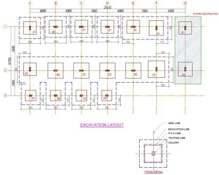
2.2 Excavation Drawing
This drawing represents the footing excavation dimension, column position, footing plan and grid lines of column.
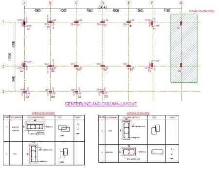
2.3 Column Layout
This drawing represents the position and orientation of columns and column reinforcement details.
2.4 Plinth Beam Layout
This drawing represents the dimensions, position and section of plinth beam and the details of reinforcement in plinth beam.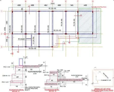
Fig 5: Plinth Beam Layout
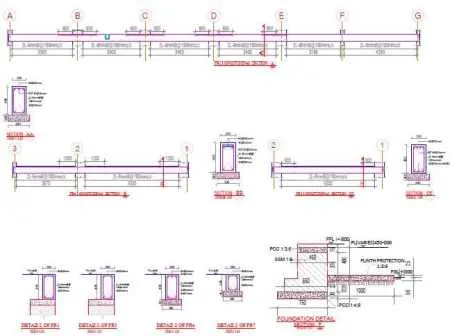
Fig 6: Plinth Beam Details
2.4 Lintel Beam Layout
This drawing represents the dimensions, position and section of lintel beam and the details of reinforcement in lintel beam.
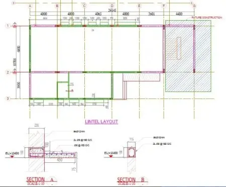
Fig 7: Lintel Beam Layout and Details
2.5 Roof Beam and Shuttering Layout
This drawing represents the details of reinforcement of roof beam, its section and shuttering details.
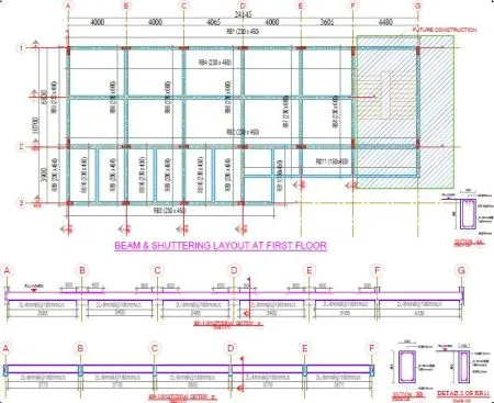
Fig 8: Roof Beam and Shuttering Layout
2.6 Roof Slab Layout
This drawing represents the details of reinforcement of roof slab, its section and openings in the roof for various purpose such as stairs or skylight.
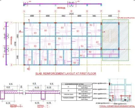
Fig 9: Roof Slab Layout
3. Electrical Drawing
Electrical drawing represent the details of electrical fixtures, location of switches, fan, light and others. It also represents the load calculation, tapping for electricity, wiring path and other interventions such as AC and UPS and its components.
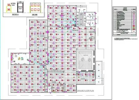
Fig 10: Electrical Drawing
4. Plumbing Drawing
Plumbing drawings give the location of sanitary, piping for water supply system, fixture, and the process to connect every fixture.
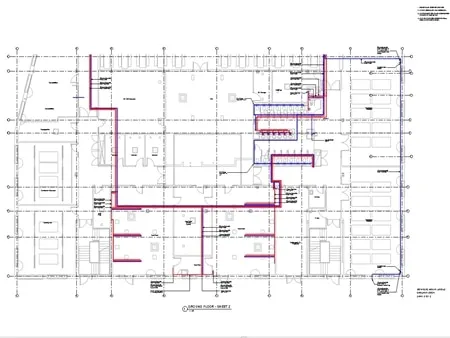
Fig 11: Plumbing Drawing
5. Finishing Drawings
Finishing drawings represents the finish type of every component of the building such as flooring pattern, painting color, false ceiling shape, plastering texture and elevation design. These details are sometime given in elevation drawings also. There is no standard rule of drawings required for a project. Depending upon the type of building and requirement, types of drawings are made and issued .
Detail drawings provide a detailed description of the geometricc form of a part of an object such as a building, bridge, tunnel, machine, plant, and so on. They tend to be large-scale drawings that show in detail parts that may be included in less detail on general arrangement drawings.
Detail drawings may be used to demonstrate compliance with regulations and other requirements, to provide information about assembly and the junctions between components, to show construction details, detailed form, and so on, that would not be possible to include on more general drawings.
They may include dimensions,tolerances,notation,symbols and specificationn information,but this should not duplicate information included in separate specifications as this can become contradictory and may cause confusion.
They may consist of two-dimensional orthogonal projections showing plans, sections and elevations and may be drawn to scale by hand, or prepared using Computer Aided Design (CAD) software.However,increasingly,building information modelling (BIM) is being used to create detailed three-dimensional representations of buildings and their components.
Detail drawings may be confused with detailed design drawings,which might describe the drawings produced during the detailed design stage,(sometimes referred to as 'developed design' or 'definition'). Detailed design is the process developing the design so that it is dimensionally correct and co-ordinated, describing all the main components of the building and how they fit together. Not all drawings produced during this stage will necessarily be detail drawings.
They are also distinct from the definition of ‘working drawings’ which provide dimensioned, graphical information that can be used by a contractor to construct the works, by suppliers to fabricate components of the works or to assemble or install components.Again,not all working drawings will necessarily be detail drawings.
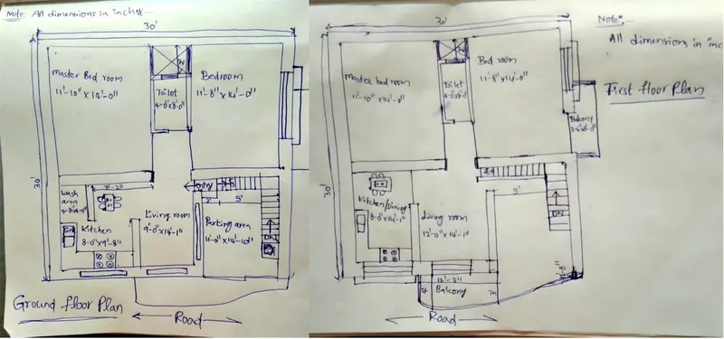
assumed beam size 225 mm x 300 mm
dead load of the beam = 0.25x0.3x25 = 1.875 kN/m
assumed column size 230 mm x 230 mm,height of the column is 3m
dead load of the column = 0.23x0.23x3x25 = 3.9675 kN
assumed slab thickness = 150 mm
dead load of the slab = 0.15x25 = 3.75 kN/m^2
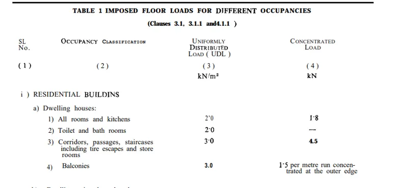
As per IS 875 part-3 since the building height is less than 10m wind load shall not be considered.