Sketch a G+1 residential plan according to Vaastu Shastra and Calculation of Loads as per IS code
AIM:
- Sketch a G+1 floor residential plan, according to Vaastu Shastra, and list down the names of the structural drawings required to be provided to the site for construction.
- Also, assume the sizes of the structural elements (Column, Beam, Slab, etc.,) and accordingly calculate the individual corresponding loads from the members as per IS code.
INTRODUCTION:
Vastu Shastra:
- Vastu Shastra is the ancient Indian science of architecture and acts as a guideline to design your home in the way that enhances positive energy.
- Our nature is abundant with powerhouses of energy sources like the sun, wind, moon, water, earth and fire.
- Effect of sunrays, flow of winds, pull of earth's magnetic field and other such cosmic energies.
- A good home needs to radiate the right kind of energy.
- A person dwelling in a house comes under the influence of a specific energy field which comes under the influence of specific energy field.
- Architectural changes are not possible for a ready to move in house.
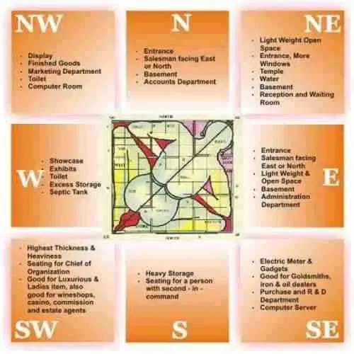
- Significance of Eight direction:
- Four cardinal direction North, South, East and West.
- Four intercardinal direction North-east, North-west, South east and South-west.
- Each direction signifies as aspect of life and is governed by various gods.
- North - Wealth
- South - Dharma
- West and East - Overall prosperity
- Basic principles of Vastu Shastra:
- Shape: Rooms Should be preferably be square or rectangle.
- Room Basics: Rooms should be airy, well lit, bright and clean.
- Home centre: Centre of the house should be an empty space.
- Stairs and Furniture: Heavy furniture should be kept in the south-west direction.
- Water: Avoid keeping plants and water features in the beadroom.
- Dining Table: Dining space should be near the kitchen and not near the main door.
- Mirror placement: Mirror facing the bed is strictly not allowed. Mirrors in the bedroom need to be placed in such a way that the bed cannot be seen.
- Auspicious directions as per Vastu Shastra:
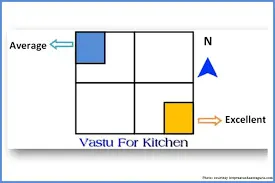
- Kitchen: South-east is the best and North-east to be avoided
- Staircase: South-west is the best and North-east to be avoided
- Toilet: North-west is the best and North-east to be avoided
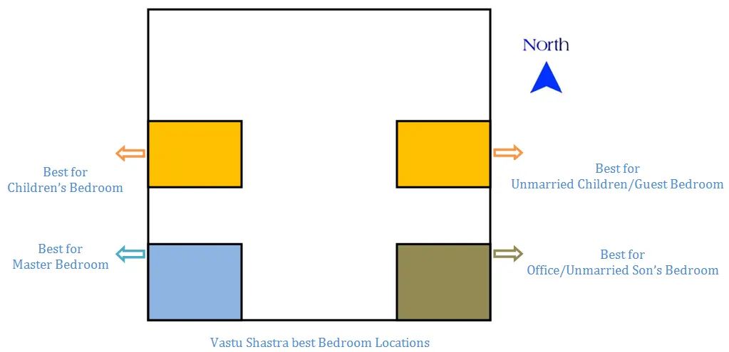
- Master Bedroom: South-west is the best
- Guest Room: North-west is the best
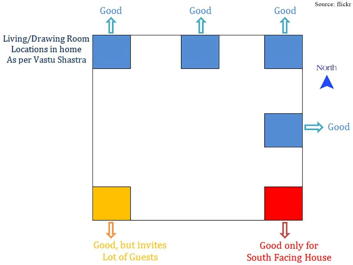
- Living Room: North-west is the best
- Over Head Tanks: West is the best
- Under ground Tanks: South-west to be avoided
Procedure:
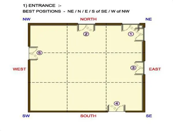
- Gateway (Entrance) of the house:
- Main entrance is not only the entry point for the family but also for energy.
- Main door should be stronger and bigger than other doors in the house and made of superior quality wood preferably teak wood.
- Main door should not be dark because good energy is associated with bright and cheery places.
- Garbage bags, unwanted things and shoes should be kept away from the main door.
- Main door should open inward and avoid creaky sounds.
- The main door should be constructed in a way to ensure that when you step out, you face the North, East or in the North-east direction.
- Avoid painting the main door black and placing of animal statues near the door.
- Entrance Best Positions: NE/N/E/S of SE/W of NW
- Living Room:
- Living room should be cluster free and it is the place where the family spends most time together.
- Living room should face East, North or North-east. North-west facing living room is also favourable.
- Heavy furniture should be kept in the West or South-west direction of the living room.
- Electronic appliances should be installed in the South-east section of the living room.
- If planning for a mirror in this room, ensure you place in the North wall.
- An aquarium on the North or East wall for prosperity.
- A bright picture of sunrise in the southern wall.
- Shades of Yellow, Green, Beige or Blue on walls to infuse liveliness and vibrancy.
- Bed Room:
- Bedroom in south-west direction brings good health and prosperity.
- Avoid bedroom in North-east as it may cause health issues.
- Avoid in south-east zone as it may cause quarrel among couples.
- Bed should be placed in the South-west corner of the bedroom with head facing west.
- Avoid placing a mirror or television in front of the bed, because reflection causes fight and other domestic disruptions.
- Avoid having paintings depicting water or a fountain as it could cause emontional outbrusts.
- Using of aromatic oils create an oisis of calm.
- Never sleep with your head in the North.
- Avoid overhanging beams in the room to enjoy good health.
- Use solid wooden beds instead of hollow wrought-iron beds.
- Paint the bedroom walls in neutral or earthy shades that radiates positive energy.
- Bedrooms are the place for rest and repose and it's good to have soothing wall colours for a paceful aura.
- Pooja Room:
- Rooms in a house for meditation and prayers will ensure spiritual growth.
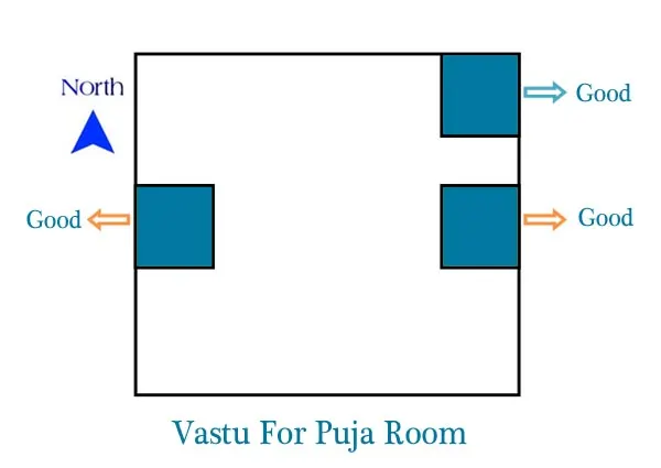
- East or North-east part of your home is perfect for meditation, Yoga and spiritual pursuits.
- Facing East when you meditate will increase positivity.
- White, beige or a light yellow or Green are great colou options for meditation room.
- Create a sacred alter and decorate with candles or incense sticks.
- Kitchen:
- Following Vastu for kitchen ensures a healthy life for your family growth.
- Keep water sink away fom the gas stove.
- Fridge needs to be placed at South-west corner.
- Never let your kitchen face a washroom wall nor share a common wall with it.
- StudyRoom:
- Select a square or rectangle shape for the study table.
- Don't place the table facing a blank wall or window.
- Placing a table in the North-east, East or West direction is ideal.
- Hanging book shelves are best avoided.
- Courtyard:
- Brahmasthan is a unique feature of ancient Architecturebased on Vastu Shastra.
- It is the center of your residence and the holiest and most powerful zone.
- A traditional home in kerala, the courtyard is always at the center of the house.
- This part should be perfect and clutter-free.
- The placement of kitchen, bathroom or pillar/bathroom or pillar/beam attracts negative energy.
- Sketch of G+1 Residential plan, according to Vastu Shastra:
- Sketch of Ground Floor and First Floor Plan.
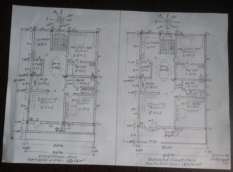
Note: (All Dimension are in Meter)
- Dimension of Ground Floor Plan.
| Drawing/Living Room | = 5.5m * 6m |
| Dining Room | = 3.5m * 5m |
| Master Bed Room | = 3.5m * 5m |
| Kids Bed Room | = 3.5m * 5m |
| Store Room | = 2m * 2m |
| Wash Room | = 1.5m * 1m |
| Toilet Room | = 3.5m * 2m |
| Toilet Rom | = 1m * 1m |
| Bath Room | = 1.5m * 2.5m |
| Kitchen | = 2.3m * 5m |
| Pooja Room | = 2.5m * 2.5m |
| Portico Area | = 9.31m * 2.5m |
- Dimension of Firat Floor Plan.
| Drawing/Living Room | = 5.5m * 6m |
| Dining Room | = 3.5m * 5m |
| Master Bed Room | = 3.5m * 5m |
| Kids Bed Room | = 3.5m * 5m |
| Store Room | = 2m * 2m |
| Wash Room | = 1.5m * 1m |
| Toilet Room | = 3.5m * 2m |
| Toilet Rom | = 1m * 1m |
| Bath Room | = 1.5m * 2.5m |
| Kitchen | = 2.3m * 5m |
| Pooja Room | = 2.5m * 2.5m |
| Balcony Area | = 9.31m * 2m |
- Assume, Dimension of Structural Element.
| Dimension of all Column | = 0.3m * 0.3m |
| Dimension of all Beam | = 0.3m *0.45m |
| Thickness of External Wall | = 0.230m (230mm) |
| Thickness of Internal Wall | = 0.150m (150mm) |
| Thickness of Slab | = 0.125m (125mm) |
| Height of the wall | = 4.5m |
| Height of wall from Ground level to First Floor | = 4.625m (4.5 + 0.125 ) |
| Total Height of wall From Ground Level to Top First Floor | = 9.25m (4.625 + 4.5 + 0.125) |
- List of Structural drawings that is mandatory to be provided to the site for Construction are:
- Centre line drawing.
- Footing and Column layout with reinforcement details.
- Column Schedule with reinforcement details.
- Plinth beam layout with reinforcement details
- First floor beam layout with reinforcement details.
- First floor Slab layout with reinforcement details.
- Lift pit and Headroom reinforcement details.
Now, there brief Explanation of these listed drawing are:
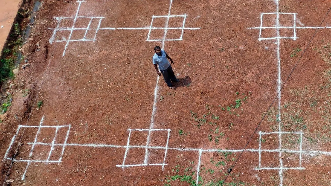
- Centre line drawing:
-
Center Line is a line that passes through the center of a column. Grid of similar lines for a number of columns form a centre line plan. Centre line plans helps you understand the exact positioning of a column on site.Column may be of different dimensions and but may have same center line. Centre line grid for columns are plotted on a land before beginning excavations. Checking for center line of a column grid ensures that columns are located at exact locations as per drawings.
Total Station Surveys are conducted to plot the center line marking over the plot.
- Footing and Column layout with reinforcement details:
- According to IS 456-2000, the minimum thickness to main reinforcement in footing should not be less than 50mm if footing is in contact with earth surface directly, and 40mm for external exposed face such as surface levelling PCC. If surface levelling is not used, then it is required to specify a cover of 75mm to cover uneven surface of excavation.
- Minimum reinforcement shall not be less than 0.12 percent of the total cross sectional area.The minimum diameter for main reinforcement should not be less than 10 mm.
- In one-way RCC footing, the reinforcement is distributed uniformly across the full width of footing. In two-way square footings, the reinforcement extending in both directions is distributed uniformly across the full width of the footing. But in the case of two-way rectangular footings, reinforcement is distributed across the full width of footing in long direction. However for short direction, the reinforcement is distributed in the central band as per calculations below. The rest reinforcement in short direction is distributed equally on both sides of the central band.
- The column is a very important part of buildings. Generally, they are used to transfer the load of the beams and slabs to the footing of the buildings. Therefore, it is very important to make it in a proper way that it can easily bear all loads which act over it
-
Based on shape & size column may be different types, such as rectangular, square, circular, etc.
- Column Reinforcement detail are:
- In case of square column, the minimum longitudinal reinforcement should be 4 nos. As per IS code, the minimum dia of the longitudinal bar should not be less than 12 mm, and the dia of a stirrup should not be less than 8 mm. Stirrup should be placed at a distance of 150 mm (centre to centre distance).
- In case of rectangular column, the minimum longitudinal reinforcement should be 4 nos. The minimum dia of bars should be same as the above mentioned.
- In case of circular column, the minimum longitudinal reinforcement should be 6 nos. Dia of bars should be same as the above mentioned.
- Column Schedule with reinforcement details:
- The column is a very important part of buildings. Generally, they are used to transfer the load of the beams and slabs to the footing of the buildings. Therefore, it is very important to make it in a proper way that it can easily bear all loads which act over it
-
Based on shape & size column may be different types, such as rectangular, square, circular, etc.
- Column Reinforcement detail are:
- In case of square column, the minimum longitudinal reinforcement should be 4 nos. As per IS code, the minimum dia of the longitudinal bar should not be less than 12 mm, and the dia of a stirrup should not be less than 8 mm. Stirrup should be placed at a distance of 150 mm (centre to centre distance).
- In case of rectangular column, the minimum longitudinal reinforcement should be 4 nos. The minimum dia of bars should be same as the above mentioned.
- In case of circular column, the minimum longitudinal reinforcement should be 6 nos. Dia of bars should be same as the above mentioned.

- Plinth beam layout with reinforcement details:
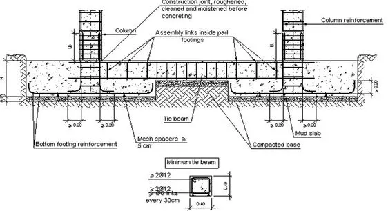
- It is a foundation or platform that holds another structure, column, or plinth in place. In construction, the plinth disperses weight and pressure uniformly down a column over a larger area. You can raise buildings above the ground to shield structures from the elements or water.
- The primary purpose of the plinth height is to shield the superstructure from moisture that can leak in due to direct ground contact. The damp proof course, which offers additional moisture protection, is installed on the top level of the plinth.
- According to the bylaws, the plinth cannot be any shorter than 45 cm. The prerequisites for a plinth area are as following
- To prevent dampness, moulds and moisture from entering the building
- To transfer a load of a superstructure to the foundation of the building.
- To serve as a retaining wall to prevent the filling part from rising over the higher floor or building
- To improve the architectural appearance of a building
- To provide stability to the building from all sides.
- Plinth beam Reinforcement details are:
- According to the rules, the bottom of the plinth beam has two reinforcing steel bars with a minimum diameter of 12mm. On the top are two more steel bars for reinforcement with a diameter of at least 10 mm.
- The reinforcement bars must have a concrete cover of at least 25mm thickness. The spacing between stirrups must be 15 cm, and the stirrups’ diameter cannot be less than 6 mm
- First floor beam layout with reinforcement details:
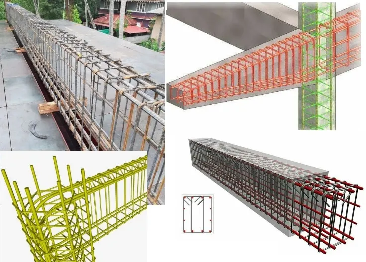
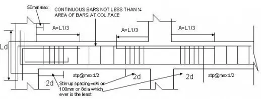
- Beam carries transverse external loads that cause bending moment, shear forces and in some cases torsion
- Concrete is strong in compression and very weak in tension.
- Steel reinforcement counter act tensile stresses in reinforced concrete beams.
- Mild steel bars or Deformed or High yield strength deformed bars (HYSD) used.
- HYSD bars have ribs on the surface and this increases the bond strength at least by 40%
- Generally a beam consists of following steel reinforcements: Longitudinal reinforcement at tension and compression face. Shear reinforcements in the form of vertical stirrups and or bent up longitudinal bars. Side face reinforcement in the web of the beam provided when the depth of the web in a beam exceeds 750 mm.
- First floor Slab layout with reinforcement details:
- Reinforcement detailing of a slab is done based on its support conditions. Slab may be supported on walls or beams or columns. Slab supported directly by columns are called flat slab. Slab supported on two sides and bending takes place predominantly in one direction only is called One Way Slab. On the other hand, when slab is supported on all four sides and bending take place in two directions are said to be Two Way Slab. The slabs having ratio of longer length to its shorter length (Ly/Lx) greater than 2 is called one way slab otherwise as two way slab. In one way slab main reinforcement is parallel to shorter direction and the reinforcement parallel to longer direction is called distribution steel. In two way slab main reinforcement is provided along both direction.
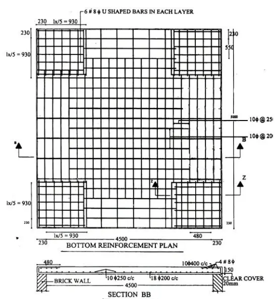
- Thickness of the slab is decided based on span to depth ratio specified in IS456-2000. Minimum reinforcement is 0.12% for HYSD bars and 0.15% for mild steel bars.
- The diameter of bar generally used in slabs are: 6 mm, 8 mm, 10 mm, 12mm and 16mm. The maximum diameter of bar used in slab should not exceed 1/8 of the total thickness of slab.
- Maximum spacing of main bar is restricted to 3 times effective depth or 300 mm whichever is less. For distribution bars the maximum spacing is specified as 5 times the effective depth or 450 mm whichever is less.
- Generally 15mm to 20mm cover is provided for the main reinforcements.
- Alternate main bars can be cranked near support or could be bent at 1800 at the edge and then extended at the top inside the slab
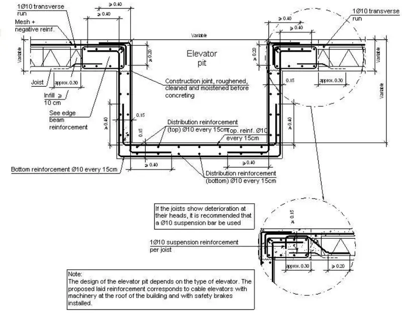
- Lift pit and Headroom reinforcement details:
- A lift is a system permanently installed that serves for vertical (or in the direction smaller than 15% from perpendicular) transport of persons or goods in lift cars or on platforms.
Here, there are three basic Part are;
-
Headroom: a part of the shaft between the level of the highest stop and the shaft’s ceiling.Travel: the length of the cabin’s travel between level of the lowest and the highest stop.Pit: a part of the shaft below level of the lowest stop.
- Now here, Lift Pit Reinforcemnt detail are given below;
- Load Calculation:
Here, we assume data for the above Sketch Plan are;
- Dimension of Structural Element.
| Dimension of all Column | = 0.3m * 0.3m |
| Dimension of all Beam | = 0.3m *0.45m |
| Thickness of External Wall | = 0.230m (230mm) |
| Thickness of Internal Wall | = 0.150m (150mm) |
| Thickness of Slab | = 0.125m (125mm) |
| Height of the wall | = 4.5m |
| Height of wall from Ground level to First Floor | = 4.625m (4.5 + 0.125 ) |
| Total Height of wall From Ground Level to Top First Floor | = 9.25m (4.625 + 4.5 + 0.125) |
Here, we assumed for given Sketch plan total no. of column = 10 (i.e., C1, C2, C3, C4, C5, C6, C7, C8, C9, C10 )
And we assume that total no. of Beam=1 (i.e., connecting to Column C3, C10 and C7 )
And also we assume that size of the given plan are;
Let,
| Drawing/Living Room | = 5.5m * 6m |
| Dining Room | = 3.5m * 5m |
| Master Bed Room | = 3.5m * 5m |
| Kids Bed Room | = 3.5m * 5m |
| Store Room | = 2m * 2m |
| Wash Room | = 1.5m * 1m |
| Toilet Room | = 3.5m * 2m |
| Toilet Rom | = 1m * 1m |
| Bath Room | = 1.5m * 2.5m |
| Kitchen | = 2.3m * 5m |
| Pooja Room | = 2.5m * 2.5m |
| Portico Area | = 9.31m * 2.5m |
| Balcony | = 9.31m * 2m |
assume total length of Beam = Length of Floor Plan - 0.5m
= 19.06 m- 0.5m
= 18.56m
i.e., Length of Beeam = 18.56m
Height of wall = 4.5m
i.e., assume Height of wall is equal to Height of Column with Slab= 4.625m
Now, the unit weight of the RCC (Reinforcement cement concrete ) are taken as approx. equal to 25kN/m^3 from table-1 clause no. 22 of IS 875 (Part-1 ):1987
- Step For Load Calculation are;
- For Ground Floor Load Calculation:
- Dead Load Calculation:
1. Dead Load For Column:
given, size of column = 300mm x 300mm
= 0.3m x 0.3m
= 0.09m^2
Volume of Column = Seize of column x Height of column
= 0.09 x 4.625
= 0.416m^3
Dead Load of column = volume of column x Unit weight of RCC (Reinforced cement concrete)
= 0.416 x 25
= 10.4 KN
As, per design Total 10 number of column are Provoided
so, here, total Dead load of column = total no. of column x 10.4 KN
= 10 x10.4
= 104 KN
2. Dead Load For Beam:
given, size of Beam = 300mm x 450mm
= 0.3m x 0.45m
= 0.135m^2
Volume of Beam = Seize of Beam x Length of 1m Beam
= 0.135 x 1
= 0.135m^3
Dead Load of Beam = volume of Beam x Unit weight of RCC (Reinforced cement concrete)
= 0.135 x 25
= 3.375 KN
so, here, total Dead load of Beam = total length of Beam x 3.375 KN
= 18.56 x 3.375
= 62.64 KN
3. External Wall dead load on beam:
Wall load on beam = Dead load of wall
Height of the wall = 4.625m
Thickness of the external wall = 0.23m (230mm)
Unit weight of brick wall = 20KN/m3
Dead load of wall = (Height of wall x Thickness of the external wall) x Unit weight of brick wall
= 4.625 x 0.230 x 20
= 21.275 KN/m
External Wall load on beam= 21.275 KN/m
Lets, assume total Length External wall = 52.04m
Then, Total Dead Load of External Wall = 52.04 x 21.275
= 1107.151 KN
4. Internal Wall dead load on beam:
Wall load on beam= Dead load of wall
Height of the wall=4.625m
Thickness of the interior wall=0.150m (150mm)
Unit weight of brick wall = 20 KN/m3
Dead load of wall= (Height of wall x Thickness of the Internal wall) x Unit weight of brick wall
= 4.625 x 0.150 x 20
= 13.875 KN/m
Internal Wall load on beam= 13.875 KN/m
Lets, assume total Length Internal wall = 41.5m
Then, Total Dead Load of Internal Wall = 41.5 x 13.875
= 575.812 KN
5. Dead Load For Slab:
Self weight of Slab = Dead Load of Slab
Given, Thickness of Slab = 0.125m (125mm)
Let's accroding to Length of Beam = Length of Slab
= 18.56m
For the Above given plan let's assume the size of Slab are.
Length of Slab = 18.56m
Width of Slab = 9.61m
So, The Total Area of Slab = 18.56 x 9.61
= 178.36m^2
And, Volume of Slab = Area of Slab x Thickness of Slab
= 178.36 x 0.125
= 22.295m^3
Then, Dead Load of Slab = Volume of Slab x Unit weight of RCC
= 22.295 x 25
= 557.375 KN
6. Self weight of ceiling= 0.25KN/m^2 (As per IS 875 Part 1)
Assume, Total Area of celling = Area of Slab
= 178.36m^2
Then, Total Self weight of celling = 178.36 x 0.25
= 44.59 KN
7. Self weight of roofing= 0.83Kn/m^2 (As per IS 875 Part 1)
Assume, Total Area of roofing = Area of Slab
= 178.36m^2
Then, Total Self weight of roofing = 178.36 x 0.83
= 148.03 KN
8. Floor Finish=1KN/m^2 (As per IS 875 Part 1)
Assume, Total Area of Floor Finish = Area of Slab
= 178.36m^2
Then, Total Floor Finish = 178.36 x 1
= 178.36 KN
Hence, Total dead Load = Sum of all above number of Load i.e., (1+2+3+4+5+6+7+8 )
= (104 KN+ 62.64 KN + 1107.151 KN + 575.812 KN +557.375 KN + 44.59 + 148.03 + 178.36 )
Total Dead Load = 2777.958 KN
- Live Load Calculation:
Here, for Live Load Calculation for the above mention Plan are Calculated by using IS code 875 ( Part 2 )- 1987 for Table-1
Imposed Floor Load for Different Occupancies are,
| Drawing/Living Room | = 3 KN/m^2 |
| Dining Room | = 3 KN/m^2 |
| Master Bed Room | = 2 KN/m^2 |
| Kids Bed Room | = 2 KN/m^2 |
| Store Room | = 3 KN/m^2 |
| Wash Room | = 2 KN/m^2 |
| Toilet Room | = 2 KN/m^2 |
| Toilet Rom | = 2 KN/m^2 |
| Bath Room | = 2 KN/m^2 |
| Kitchen | = 2 KN/m^2 |
| Pooja Room | = 2 KN/m^2 |
| Portico Area | = 3 KN/m^2 |
| Balcony | = 3 KN/m^2 |
| Tarrace | = 3 KN/m^2 |
| Total Load | = 34 KN/m^2 |
So, The Total live Load for the above Plan of These Occupancies are = 3+3+2+2+3+2+2+2+2+2+2+3+3+3 (for Sum of all Floor Load )
= 34 KN/m^2
Let's Assume Total Occupancies Area = Total Build up Area
= 183.16m^2
So, Total Live Load = 183.16 x 34
Total Live Load = 6227.44 KN
- Wind Load Calculation:
Here, for the above plan,
Total Height of the Ground Floor wall = Height of wall + Thickness of Slab
= 4.5m + 0.125m
= 4.625
So, Total Height of the Building = Height of Ground Floor Wall + Height of First Floor Wall
= 4.625m + 4.625m
= 9.25m
But, we Know that For wind load Calculation, Total Height of the Building required for 10m height above mean ground level for different zone of the country. ( It is Considered from IS 875 ( Part 3)-1987 from Clause no. 6.2 Basic wind Speed.)
i.e.,
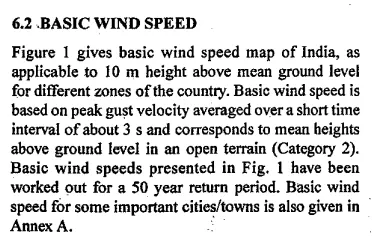
So, There is not required for Calculation of Wind Load because the Total height of the wall is Less than 10m
i.e., 9.25m
Now,
The Total Load Acting on the Ground Floor = Sum of Total Load (Dead Load + Live Load + Wind Load )
= [ 2777.958 KN + 6227.44 KN + 0 (note Considered ) ]
Total Load acting on Ground Floor = 9005.398 KN
NOTE: As the size are same for the first floor so all load calculation are same as ground floor load calculation
i.e., Total Load acting on First Floor = 9005.398 KN
Then, Total Load acting on Building = (Load acting on Ground Floor + Load acting on First Floor )
= 9005.398 KN + 9005.398 KN
Total Load acting on Building = 18010.796 KN
Results :-
- The plan of G+1 Floor Residential Building is prepared with consideration of Concept of Vaastu Shastra.
- The load calculations are done as per the IS code considerations.
References and IS codes used for the design :-
- IS 875 :1987 (Part 1) for Dead load
- IS 875 :1987 (Part 2) for Live load
- IS 875 :1987 (Part 3) for Wind load
- IS 456 :2000 for Reinforced Concrete