Sketch a G+1 residential plan according to Vaastu Shastra and Calculation of Loads as per IS code
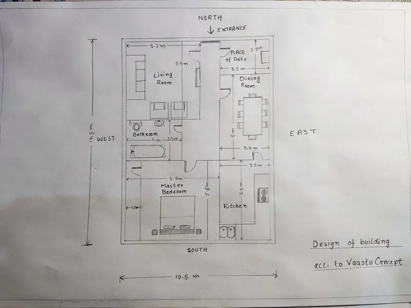
Sketch of Single Floor Residential Plan as per Vaastu Sastra:
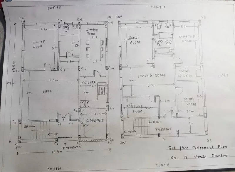
Sketch of G+1 Residential Plan as per Vaastu Sastra:
. Important Structural Drawings that is provided to the site:
- Centre line drawing:
In structural drawing, center line drawings are used to show the centerline of a structural element such as a column, beam, or wall. The centerline is an imaginary line that runs through the center of the element, dividing it into two symmetrical halves. Center line drawings are important in structural design because they help to ensure that the structural elements are placed correctly and that their dimensions and positions are accurately represented.
- Footing and Column layout with reinforcement details:
Footing and column layout with reinforcement is an important aspect of structural design and construction. Footings provide a stable foundation for columns or walls, which in turn support the weight of the structure above. Reinforcement is added to footings and columns to provide additional strength and stability, especially in areas with high seismic activity.
The layout of the footings and columns with reinforcement typically includes the following steps:
- Determine the load requirements for the structure: The design of the footing and column layout with reinforcement begins by calculating the loads that will be imposed on the structure. This includes the weight of the structure, as well as any additional loads such as wind or earthquake forces.
- Determine the size and location of the footings: The size and location of the footings are determined based on the load requirements and the type of soil at the building site. The footing must be large enough to distribute the load of the structure evenly across the soil.
- Determine the size and location of the columns: The size and location of the columns are determined based on the load requirements and the structural design of the building.
- Column Schedule with reinforcement details:
A column schedule with reinforcement details is a document that provides information on the dimensions, materials, and reinforcement requirements for each column in a building. The schedule typically includes a table that lists the column number, size, height, and other relevant information, as well as drawings or sketches that show the specific reinforcement details for each column.
- Plinth beam layout with reinforcement details:
A plinth beam is a reinforced concrete beam that is located at the ground level of a building, just above the foundation. The purpose of a plinth beam is to distribute the load of the building evenly across the foundation, and to protect the structure from soil settlement and other types of damage.
- First floor beam layout with reinforcement details:
A first-floor beam is a structural element that supports the weight of the floor and any additional loads, such as furniture, appliances, or people. The beam is typically made of reinforced concrete and is designed to distribute the load evenly across the supporting columns and walls.
- First floor slab layout with reinforcement details:
A first-floor slab is a horizontal structural element that provides a surface for people, furniture, and equipment to stand on. It is typically made of reinforced concrete and is designed to support the weight of the floor and any additional loads
- Lift pit and headroom reinforcement details:
Lift pit reinforcement refers to the process of strengthening the area at the bottom of an elevator shaft, also known as the pit, in order to ensure that it can support the weight of the elevator and its passengers. This is typically achieved by installing additional steel or concrete reinforcement, such as reinforcing bars or mesh, around the perimeter of the pit.
We have to calculate the dead load (DL), live load (LL) and wind load (WL) of the above plan
- Calculation of Dead load:
- Calculation of column
As shown in fig there are 34 column
Unit weight of RCC = 25 KN/m3
Dead Load of Column = 0.3*0.3*25*18 = 40.5 KN/m
Dead Load of Beam = 0.3*0.45*25 = 3.375 KN/m
Dead Load of Slab = 0.125*25 = 3.375 KN/m2
Dead Load of wall = 0.23 *4.5*19 = 19.665 KN/m … here 19 KN/m3 is dead load of brick
- Calculation of Live Load:
- As per IS 875(part II) Table 1 for Residential Building
- All rooms and kitchen = 2 KN/m2
- Toilet and bathroom = 2 KN/m2
- Corridors, passages, staircase
Including true escape and store = 3 KN/m2
Rooms
- Balconies = 3 KN/m2
- Calculation of Wind Load:
- As per IS 875(paart III) the intensity of wind Load depends upon the velocity of wind , size and height of the building.
Pz = 0.6*Vz2 Vz = Vb*k1*k2*k3
- Vz = Design wind speed @ height z, in m/s
- Pz = Wind pressure @ height z, in N/m2
- Vb = Basic Wind speed
- K1 = Probability factor (Risk Co-efficient)
- K2 = Terrain roughness and height factor
- K3 = Topography factor
- K4 = Importance factor
Note: Wind speed may be taken as constant up to a height of 10m. However, pressure for building less than 10 m high may be reduced by 20% for evaluating stability and design of the framing