Sketch a G+1 residential plan according to Vaastu Shastra and Calculation of Loads as per IS code
Aim:
1.To plot a residential plan for G+1 building according to Vaasthu Shastra.
2.List of Structural drwaings to be provided for construction.
3.Caluculation of different loads acting on the building as per IS codes.
Introduction:
Vaasthu Shastra:
It is the ancient science of architecture and acts as a guideline to design a home in the way that enhances positive energies like effect of Sunrays , flow of winds, pull of earth's magnetic field and other cosmic energies.
A person dwelling in a house comes under the influence of a specific energies filled such comes under the influence of specific energy field.
Auspicious dierections as per Vaasthu sastra:
1.Kitchen: South East is the best and North East is avoided.
2.Living room:North West is best.
3.Master bedroom: South west is best
4.Guest room: North West is best.
5.Toilet: North west is best and North east is avoided.
6.Staircase: South west is best and North East is avoided.
7.Over head tank: West is preferred.
8.Underground tank: North east is preferred.
Structural drawings:
A detailed set of structural drawings prepared by structural engineer helps the construction process to go smoother by better understanding of drawings by site engineers.
Loads caluculation by IS codes:
Different types of Loads acts on a structure like dead load, live load, wind load, seismic load etc. These are caluculated well in advance by using specified IS codes which are explained in detail below.
Procedure:
Plan for G+1 building:
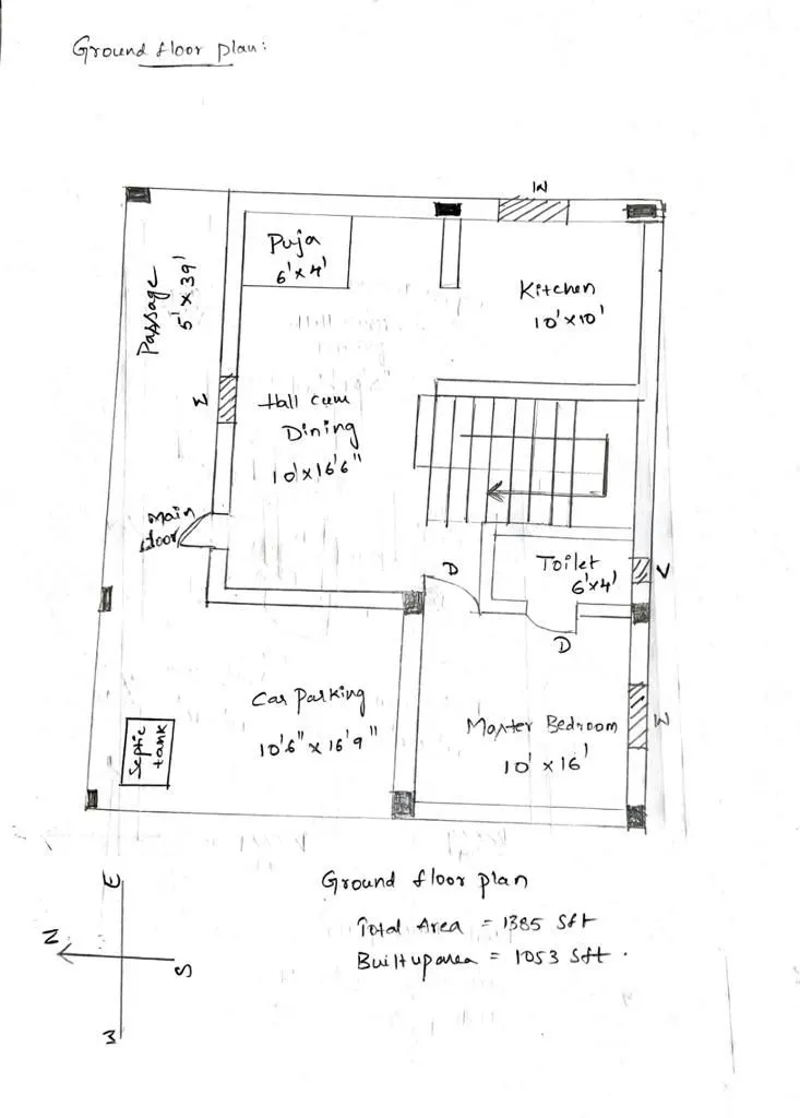
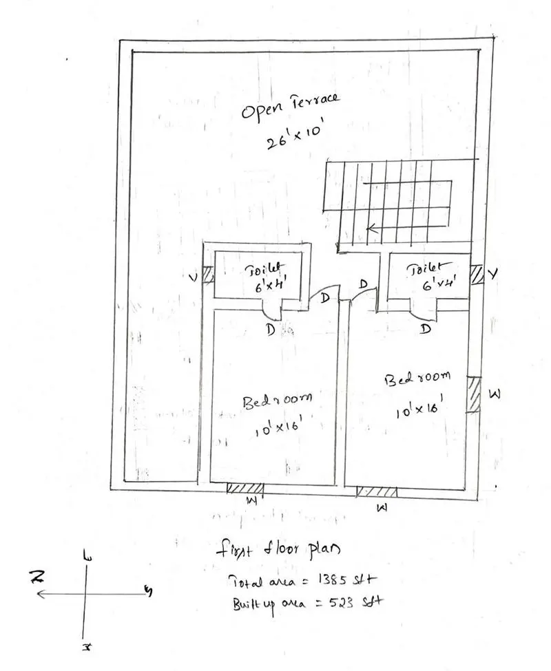
Dimensions for GF:
1.Living room cum dining=10'*16'6"
2.Pooja room=6'*4'
3.Kitchen=10'*10'
4.Master bedroom=10'*16'
5.Toilet=6'*4'
6.Car parking=10'6"*16'9"
7.Passage=5'*39'
Dimensions for FF:
1.Bedroom 1=10'*16'
2.Bedroom2=10'*16'
3.Toilet1=6'*4'
4.Toilet 2=6'*4'
5.Open terrace=26'*10'.
Here assumed data,
1.Thickness of external and internal walls=230mm=0.23m.
2.Thickness of slab=250mm=0.25m.
3.Columns=0.65m*0.65m.
4.Beam=0.3m*0.45m.
5.Height of the wall of GF=4m.
6.Height of wall of FF=4m.
List of Structural drwaings to be provided for construction:
1.Center line drawing
2.Footings and Column layout with reinforcement details
3.Column schedule with reinforcement details
4.Plinth beam layout with reinforcement details
5.First floor beam layout with reinforcement details
6.First floor slab layout with reinforcement details
7.Liftpit and Head room reinforcement details.
Types of Drawings:
Architectural drawings
Structural drawings
Electrical and Plumbing drawings
HVAC drawings
Fire fighting drawings etc.,
Architectural drawings:
Site Plan drawings:
An Architectural Site Plan is an aerial view of the construction site that includes the primary building and its adjoining constructions.
Among its wide applications, we can include construction drawings for building improvement and understanding the scope of construction activities.
Along with it, it helps identify the topography of the building including roads, pavements, etc.
Floor Plan drawings:
These are in-depth versions of the room layout. Architectural Floor plans are made irrespective of the fact that they are to be utilized during the construction of a home, shop, or commercial project.
Cross section drawings:
Architectural Cross-sections drawings allow the architect to look at the different components of a building vertically.
This 2-dimensional imagery is helpful to provide an overview of both the visible and hidden components of a building.
Elevation drawings:
Elevations drawings help an architect understand the facing of the building. It is useful to know about the direction of the sun and the wind corresponding to the building.
They also indicate the height of the building and the external and internal marking which includes the doors, and sizes of the windows too.
Structural drawings:
Foundation plan:
Foundation plans are not necessarily basement plans or ground floor plans. A foundation plan can be made for any floor of a building.
The purpose of making these plans is to convey the dimensions, sizes, shapes, and every single configuration of a floor. Footings are also an essential part of a foundation plan.
Column layout:
Column layout reinforces the design and pattern of the columns of the whole structure. This plan is divided floor-wise and demarcates the exact size and distance between every column of the building.
Column layout drawings further make it easier for the contractors to make sense of the whole building layout.
Plinth beam layout:
Plinth beams are yet another form of beam structure that reinforces the support system of a building.
The plinth beam layout drawings showcase the position, length, and sectional design of the plinth beams. Here too, the plinth beams drawings are also made floor-wise.
Lintel beam layout:
Lintel beams are yet another form of support structure that are made above the doors and windows.
These are reinforced structures that are made to provide strength to the part of the building that is made above the windows and doors.
In these kinds of drawings, you will find the correct positions, dimensions, and the number of lintel beams on every floor.
Roof beam layout:
A roof beam is made to strengthen the building’s overall structure.
A roof beam is a triangular structure that is usually made on the top of the building and supports the roof.
Roof beams are usually made out of wood, but it can also be made from steel or concrete.
Roof Slab layout:
The roof slab layout is more prominently made in the AutoCAD architectural software.
The main purpose of the roof slabs is to provide a detailed account of the floors, roof faces, and other such surfaces that require precise edge information.
Electrical and Plumbing drawings:
An electrical drawing represents an in-depth account of all the electrical connections, outlets, fixtures, switches, lighting, fans, and everything else.
These drawings provide pillar support to the electricians allowing them to understand the wiring layout on the floor.
Similar to the electrical drawings, the plumbing construction plans show the markings and the location of the plumbing components.
HVAC drawings:
Also called mechanical drawings, the HVAC drawings provide information about the heating and ventilation systems.
They also include the air conditioning patterns and layout that are to be constructed inside the building.
The HVAC drawings provide an insight into these complex systems and help the builders plan their construction process accordingly.
Fire fighting drawings:
Firefighting drawings are drawn before the construction of a building. They draw out the pattern of the placement of the fire hoses, points, water outlets, and everything else.
They also lay out the fire protection plan and safety systems that are to be set in place.
Calculations of loads:
A.Dead Loads Caluculation:
1.Dead load of Columns:
Here according to plotted plan, number of columns=9.
Dimension of column=0.65m*0.65m.
Height of column=(Slab thickness*2)+Height of wall of GF+Height of wall of FF
=(0.25*2)+4+4
=8.5m.
Total volume of one column=0.65*0.65*8.5=3.59m^3.
Unit weight of RCC=25KN/cu.m. (confirming to IS 875 Part 1)
Therefore, dead load of all columns=Volume of column*Number of columns*Unit weight of RCC
= 3.59*9*25
= 807.75 KN.
2.Dead load of Beams:
Dimension of beam=0.3m*0.45m.
Total volume of beam per meter length=0.3*0.45*1=0.135cu.m.
Unit weight of RCC Beam=25KN/cu.m (confirming to IS 875 part 1)
Therefore, dead load of beam per unit length=volume of beam*unit weight
= 0.135*25
=3.375KN.
Dead loads of all beams= 3.375x10=33.75 KN
3.Dead load of Slabs:
Slab is always designed for for the span of 1m^2 area.
Thickness of slab=0.25m (assumed data).
Unit weight of RCC=25KN/m^3 (confirming to IS 875 part 1)
Total volume of slab per 1 square meter span area=1*1*0.25=0.25m^3.
Dead load of slab (per square meter area)=Volume of Slab*Unit weight of RCC
=0.25*25=6.25KN.
According to plotted plan, Slab area for GF=11.89m*8.23m=98m^2 (approximate)
Therefore dead load of GF Slab=98x6.25=612kn.
Slab area for FF=60sq.mx6.25=375Kn
4.Dead load of walls:
Thickness of external and Internal walls=0.23m (assumed data)
Unit weight of brick masonry=20KN/m^3 (confirming to IS 875 part 1)
Height of GF wall=4m.
Dead load of GF wall per unit meter length=Volume of GF wall per unit length*Unit weight of masonry
=(0.23*4*1)*20
=18.4KN.
Height of FF wall=4m(assumed data)
Dead load of FF wall per unit meter length=Volume of FF wall per unit length*Unit weight of masonry
=(0.23*1*4)*20
=18.4KN.
Total weight of both GF and FF walls per unit meter length=18.4+18.4=36.8KN.
5)Dead load of Staircase:
Load on beams= (Total load on waist slab x Distance of load carrying direction)/2
= (10.39 x 4.6)/2
= 23.9 Kn/m
B.Live Load Caluculations:
As per IS 875 part 2, for a residential building, live loads will be taken as follows.
Living/Dining=2KN/m^2
Kitchen=2KN/m^2
Bed room=2KN/m^2
Toilet=2KN/m^2
Terrace=3KN/m^2
Staircase=3KN/m^2.
C.Wind load Caluculations:
If the height of the building exceeds more than 10m, then building needs to be designed for wind load.
In this case, height of the building is 8m. So wind loads need not to be considered.
IS Codes referrence to be taken for Load caluculations:
1.IS 456-2000 for RCC structurers.
2.IS 875-1987 Part1 for dead load.
3.IS 875-1987 Part2 for Live Load .
4.IS 875-1987 Part 3 for Wind Load.
5.IS 1893-2016 Part 1 for Seismic Loading.
6.IS 13920-1993 for Seismic detailing.