Sketch a G+1 residential plan according to Vaastu Shastra and Calculation of Loads as per IS code
Aim of the project-
- To sketch a G+1 floor residential plan according to vastu Shastra and to list down the names of structural drawings required to be provided to the site for construction.
- To assume the size of structural elements (Column, Beam, slab etc) and to calculate the loads from the members as per IS code.
Ground Floor plan-
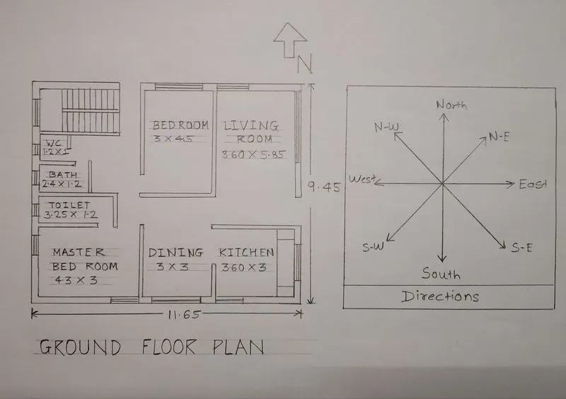
(Dimensions are in Meters)
- Dimensions of Ground Floor plan-
- Living room- 3.60m X 5.85m
- Kitchen room- 3.60m X 3m
- Dining room- 3m X 3m
- Master bedroom- 4.3m X 3m
- Bedroom- 3m X 4.5m
- Toilet- 3.25m X 1.2m
- Bath- 2.4m X 1.2m
- WC- 1.2m X 1m
First Floor plan-
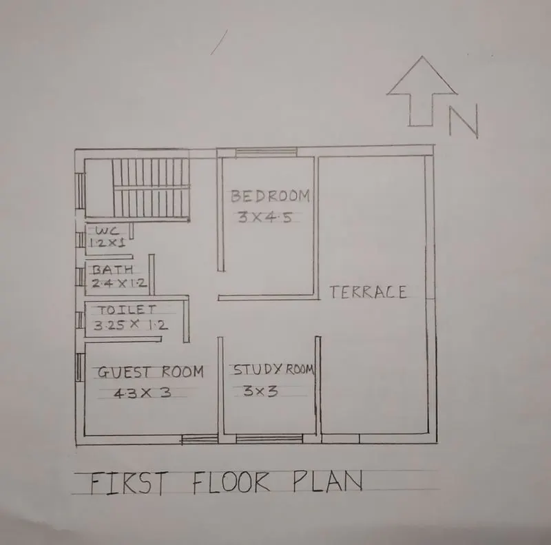
(Dimensions are in Meters)
- Dimensions of First Floor Plan-
- Guest room- 4.3m X 3m
- Study room- 3m X 3m
- Bedroom- 3m X 4.5m
- Toilet- 3.25m X 1.2m
- Bath- 2.4m X 1.2m
- WC- 1.2m X 1m
Other dimensions
- Thickness of internal wall- 0.15m (150mm)
- Thickness of external wall- 0.23m (230mm)
- Thickness of slab- 0.25m (250mm)
- Dimensions of column – 0.3m X 0.3m
- Dimensions of beam-0.3m X 0.45m
- Height of the wall of each floor- 3m
Vastu Shastra followed during planning is-
- Entrance of the house is provided in the east direction which is the symbol of progress in life.
- Living room is placed in north east direction.
- Master bedroom is placed in south west position this direction brings good health and prosperity.
- Kitchen is placed in south east direction.
- Study room is placed in east direction.
- Staircase is placed at Northwest corner.
- Bathroom, WC and toilet is placed in West direction.
Concept of Vaastu
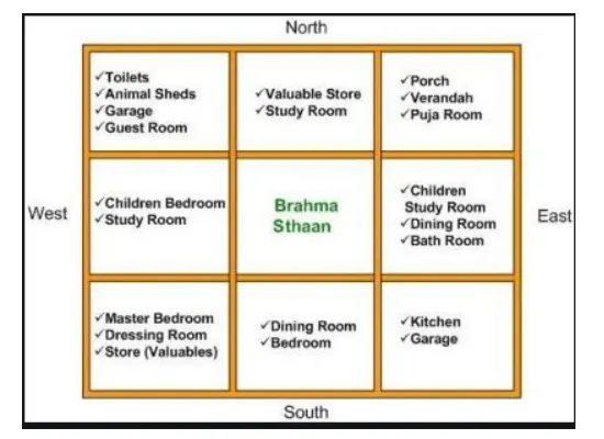
List of drawings provided at the construction project
- -Centre line drawing.
- -Footing and column layout with reinforcement details.
- -Column schedule with reinforcement details.
- -Plinth beam layout with reinforcement details.
- -First floor beam layout with reinforcement details.
- -Lift pit and head room reinforcement details.
- -Centre line drawing.
- -Floor plans.
- -Foundation plan.
- -Design drawings.
- -Block plan.
- -Roof slab layout.
- -Column layout.
- -Site plans.
- -Column sections.
- -Septic tank design.
- -Overhead water tank design.
- -Plinth beam sections
- -Flooring plan.
- -Furniture plan.
- -Road drainage plan.
- -Setting out plan.
- -Section drawings of buildings.
- -Plumbing details.
- -Electrification details.
Calculation of loads-
(A). Dead load Calculations
- Dead load of columns-
- Dimension of column= 0.3m X 0.3m (300mm X 300mm)
- Height of column= (Slab thickness X 2) + (Height of wall for each floor X 2)
- = (0.25 X 2) + (3 X 2) = 6.5m
- Total volume of concrete = 0.3 X 0.3 X 6.5 = 0.585m3.
- Unit weight of RCC= 25KN/m3.
- Unit Weight of Building Materials used in construction works as per IS 875 (Part-1)
- Dead load of column= 25 X 0.585=14.62KN.
- Dead load of beams-
- Dimension of beam= 0.3m X 0.45m (300mm X 450mm)
- Total volume of concrete = 0.3 X 0.45 X 1 = 0.135m3.
- Unit weight of RCC= 25KN/m3.
- Unit Weight of Building Materials used in construction works as per IS 875 (Part-1)
- Dead load of beam= 25 X 0.135=3.375KN
- Dead load of slab-
- Slab is always designed for the span of 1m.
- Hence assume size of slab as 1m X 1m.
- Thickness of slab= 0.25m
- Density of RCC= 25KN/m3.
- Self-weight of slab= 1 X 1 X 0.25 X 25= 6.25KN.
4.Dead load of walls
- -Dead load of external wall
- Thickness of External wall = 0.23m. (230mm)
- Unit weight of brick wall= 20KN/m3
- Unit Weight of Building Materials used in construction works as per IS 875 (Part-1)
- Height of wall = 3m.
- Load of wall on beam= 3 X 0.23 X 20= 13.8KN.
- -Dead load of internal wall
- Thickness of Internal wall = 0.15m. (150mm)
- Unit weight of brick wall= 20KN/m3
- Unit Weight of Building Materials used in construction works as per IS 875 (Part-1)
- Height of wall = 3m.
- Load of wall on beam= 3 X 0.15 X 20= 9KN.
(B). Live load calculations-
- (According to IS 875 Part 2)
- Bed room= 2KN/m2
- Living room= 2KN/m2
- Bath=2KN/m2
- Terrace = 3KN/m2
- Toilet= 2KN/m2
- Staircase= 3KN/m2
- Study room= 2KN/m2
- Kitchen= 2KN/m2
(C). Wind load calculation-
- Wind load is designed only when the height of the building exceeds 10m.
- The height of designed building is 6.5m which is less than 10m.
- So, the calculation of wind load is not required.
- References and IS codes used for the design-
- IS 875:1987, Part 1 for Dead load
- IS 875:1987, Part 2 for Live load
- IS 875:1987, Part 3 for Wind load
- IS 456:2000, for Reinforced Concrete.
Results
- The plan is prepared by the Vaastu shastra concept considering all the principles and considerations of Vaastu shastra
- The load calculations are done as per the IS code considerations.