Sketch a G+1 residential plan according to Vaastu Shastra and Calculation of Loads as per IS code
AIM:
To sketch a G+1 floor residential plan as per vaastu shastra and also calculate the loads of structural members in the plan, know the structural drawings that are to be provided to the site for construction.
INTRODUCTION:
*Vaastu shastra is the ancient Indian science for designing home which radiates positive energy by placing all the rooms in such a way that the effects of natural elements like sun, wind,air etc are positive.
*Generally kitchen is placed at south west
*Pooja and meditation room are placed in north east
*The entrance of the home should face north or east or north east for better prosperity
*Heavy furniture has to be placed at south west.
*Bed room is placed at south west.
PROCEDURE FOR DESIGNING AND LOAD CALCULATION OF MEMBERS:
*The plan is prepared following the vaastu shastra and dimensions are mentioned.
*Dimensions of structural elements,unit weight of materials are noted for load calculation
*The height of column=3.3m
*Dimensions of beams are 300mm*600mm
*Dimensions of columns are 500mm*500mm
*Thickness of slab=125mm=0.125mm
*Wall thickness=230mm=0.23m
*Height of the wall is 3m
*Unit weight of concrete is 25KN/m3
*unit weight of brick is 20KN/m3
DEAD LOAD CALCULATION:
*Dead load for column=volume of column(length*breadth*height)*unit weight of concrete
=0.5m*0.5m*3.3m*25KN/m3=0.825m3*25KN/m3=20.625KN
*Dead load for beam =volume of beam *unit weight of concrete
=0.3m*0.6m*25KN/m3=4.5KN/m it is uniformly distributed load
*Dead load for wall=thickness of wall*height of the wall*unit weight of concrete
=0.23m*3m*25KN/m3=17.25KN/m(UDL)
*Dead load for slab=Thickness of slab* unit weight of concrete
=0.125m*25KN/m3=3.125KN/m2(UDL)
LIVE LOAD/IMPOSED LOAD CALCULATION:
As per IS875 part2 table 1
Live load for all rooms including bedroom,study room,living room,pooja room , kitchen ,toilet it is 2KN/m2(UDL).
For staircase , balcony and store room it is 3KN/m2
WIND LOAD:
*The height of building is 6.6m it is less than 10m therefore effect of windload can be neglected as it is considered only when the height of the building exceeds 10m,if it is so it can be calculated as perIS875:1987 part 3.
SEISMIC LOAD: The zone in which the structure is constructed is not given,weight of the if we assume and calculate it may vary therefore it is assumed that the structure is free from seismic load.
If the weight of building is given,zone in which it is located is given then design base shear is calculated by Vb=W*Ah,
where Ah is the horizontal seismic coefficient=ZISa/2Rg
Z is zone factor,I is Importance factor,R is the response reduction factor,Sa is the spectral acceleration
The values of Z,I,R are obtained from IS1893:2002
LIMIT STATE OF COLLAPSE:
Load combination is taken as follows 1.5DL+1.5IL for normal conditions
for overturning it is 0.9DL+1.5IL here DL ,IL represent dead load and lmposed load respectively.
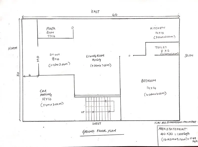
GROND FLOOR PLAN:
:
DESIGN:
*The entrance is at north as per vaastu
*Kitchen is places in south east direction as per vaastu
*Pooja room is placed in nort east as per vaastu
*Steps are placed at west beside carparking so that bedroom could be designed a bit larger actually steps in south west is advisable but due to the reduction in size of bed room , it is adopted.
*Living room is at the centre of the house, it is cluster free.
F
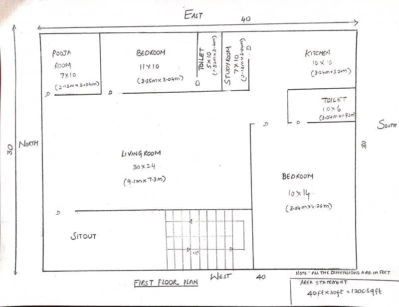
FIRST FLOOR PLAN
DESIGN:
*Kitchen is palced at south east as per vaastu
*Pooja room is placed at north east as per vaastu
*In the first floor car parking space is saved as a result it gave rise to a new bedroom.
*Dining table can be placed at the corner of the living room as it has adequate space.
*Bedroom is placed at the southwest as per vaastu.
*Steps are placed at west , to ensure space for sitout.
STRUCTURAL DRAWINGS THAT HAVE TO BE PROVIDED TO THE SITE ARE:
*Centre line drawing:
*This includes grids and their dimensioning.
*Using this, excavation is done at site.
* Footing and Column layout with reinforcement details
*Footings and columns are marked with dimebnsions along with grids
*Then the reinforcement details such as size of bar,lap length etc are detailed
*Column schedule with reinforcement details:
*Columns are marked and details of cranked bars are mentioned.
*Plinth beam layout with reinforcement details:
*It shows the beams at plinth level and reinforcement of all the beams are included.
*The bars can be differentiated on their size
*First floor beam layout with reinforcement details:
*It shows all the beams at first floor
*Reinforcement of all the beams are detailed.
slab reinforcement details:
*It includes the slab, its dimensioning
*Sunken slabs are not provided with reinforcement
First floor slab reinforcement details:
*It is similar to ground floor slab ,the detailings are done asusual.
The slab reinforcement and beam reinforcement has to be provided for each floor till the roof .
In all these drawings, directions have to be specified and revision has to be mentioned in each template for further reference.Any other important information that has to be conveyed to workers in the procedure has to be mentioned so that it can be done.