Simulink model of door bell using a solenoid and a simulink model to use a thermistor for sensing temperature.
Study1-
AIM-
In the below arrangement, when the switch is closed the electromagnet receives electrical power from the battery and pulls the metal arm to hit the bell producing sound.
Create a situation where the switch is closed for 2 seconds and then released. Observe the physical movement of the plunger.
Procedure-
Input signal - Here we are required to give a input pulse which should be zero for every two seconds which represents a off condition. So we create a pulse generator block by changing the period to 4 and pulse width to 50.By this way we will be able to generate a pulse of following pattern.
Simulink -PS converter - The signal coming from the source is converted into physical signal before giving the input to the circuit.
Battery source and Switch - In order to supply power we add a battery source and to control the oprn and close of circuit we use a switch .if the input for the switch is grater than the threshold then the switch closes otherwise the switch opens.
Solenoid-
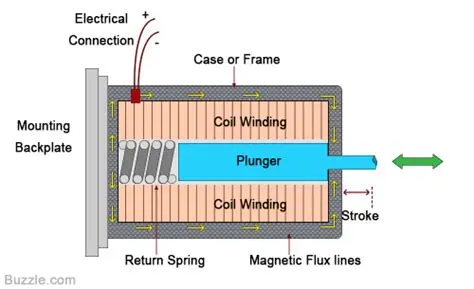
- A solenoid is a simple electromagnetic device that converts electrical energy directly into linear mechanical motion.
- The solenoid consists of a coil of wire with an iron plunger that is allowed to move through the center of the coil. When the coil is energized , the resulting magnetic field pulls the plunger to the middle of the coil.
- The magnetic force is unidirectional — a spring is required to return the plunger to its un energized position.This way the plunger operates to and fro.
- So this plunger is our arm of the bell
Connecting the solenoid,switch ,battery and input signal in a circuit-
Ideal translational sensor- In order to track the moment of the plunger we need a sensor to track it whoose output is a physical signal.
PS-Simulink converter- The ouput is from the sensor is connected to the PS-Simulink block which is connected to the scope to plot our output.
The ouput blocks Scope, display are connected to get the output.
Other blocks that are needed to be connected are the electrical and mechanical reference blocks in the respective circuits.
We also need to connect a solver configuration block to execute the algorithm correctly.
The complete circuit is as follows-
Output- The ouput of the executed block is as follows-
This is how the plunger moves with the input signal given by the pulse generator.
Study 2-
Aim-
Use a thermistor to sense the temperature of a heater & turn on or turn off the fan as per below conditions:
Temperature source: 20 °C from 0 to 10 seconds, 27 °C from 10 to 30 seconds, 23 °C from 30 to 50 seconds
Fan conditions: ON if the temperature above 25 °C, OFF otherwise.
Procedure-
Input signal - Using the signal builder block and according to the given conditions we need to create a signal as shown as below.
Controlled temperature source-
This block represents an ideal energy source in a thermal network that can maintain a controlled temperature difference regardless of the heat flow rate
Thermistor-
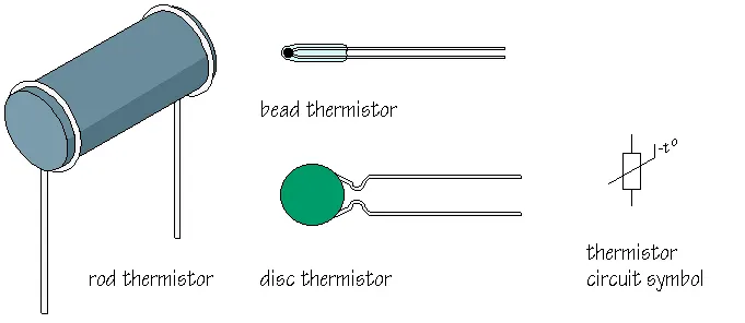
A thermistor (or thermal resistor) is defined as a type of resistor whose electrical resistance varies with changes in temperature. Although all resistors’ resistance will fluctuate slightly with temperature, a thermistor is particularly sensitive to temperature changes.
Battery-The thermistor is connected to a battery for power supply.
Ideal current sensor- This sensor is connected to get the current value that is flowing in the circuit.
let us connect the circuit with these elements but we are given a condition that only when temperatre is 25 degrees celcius the fan should turn on ,so we need to measure this threshold value of current to operate a switch .
So we give an input of 298.15K to get the threshold value of the current.
References and solver configuartions- Apart from these we need to connect the electrical and mechanical references along with the solver configuration.
Now our circuit appears as -
now when we run the circuit we get the current as 0.01198 for a given value of 298.15K .So now whenever our temperature increases this value also increases in the circuit.
Switch - inorder to operate this switch we give it a threshold value of 0.01198 ,so if the current coming to the switch is more than threshold then the current flows and ouput is adjustes as a consatant 1 ,when the current is less than the threshold then the output is a constant zero.
ON/OFF condition of Fan - now if the output is a constant 1 then the fan is in a ON condition ,if the output is 0 then the fan is in OFF condition .
Scope - These ouputs are sent to scope block we can graphically view the ON/OFF state of the fan.
Also we need to now connect the input which we have designed by using the signal builder.
We should also make sure that we change the run time to 50 seconds.
Model-
Output-
So we can see here the amplitude is zero whenever the fan is in OFF condition and the amplitude is 1 whenever the fan is in ON condition. Whenever the temperature is more than 298.15 K, the fan is ON and whenever it is less than 298.15 the fan is OFF.