Simulink Model for Door Bell & Temperature Controlled Fan
Objective: The objective of this project is to build simulink models of
a) Door Bell
b)Temperature Controlled Fan
Door Bell:
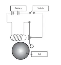
The following schematic diagram was followed to create the simulink model
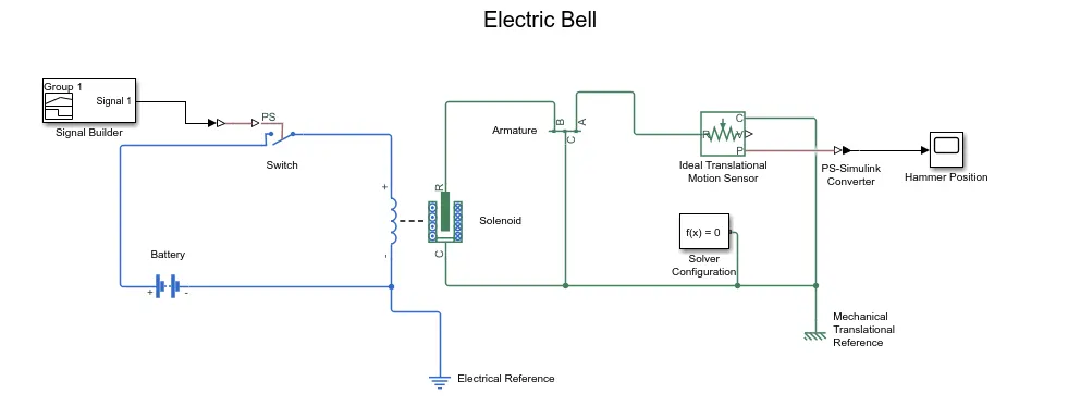
Using the following blocks the simulink model of the door bell was created
- Signal Builder
- Simulink-PS Converter
- Battery
- Solenoid
- Switch
- Electrical Reference
- Lever (armature)
- Ideal Translational Motion Sensor
- PS-Simulink Converter
- Mechanical Translational Reference
- Solver Configuration
- Scope (Hammer Position)
Fig: Simulink Model of Electric Bell
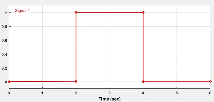
The input signal provided using the signal builder block is shown below.
Fig: Input Signal
For the solenoid block the stoke (air gap) = 5mm and the damping=5 was provided. In order to avoid the vibration in the armature when the solenoid is deactivated or activated the damping value was changed and this was done using differnent values and checking the position of the hammer for any vibrations. The stop time to run the simulation was 6 sec as per the input signal
Fig: Hammer Position
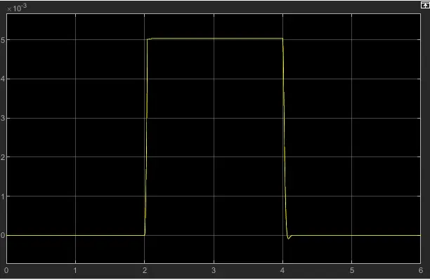
Observation: At 2sec the input changed from 0 to 1, and the soleonoid gets activated pulling the armature towards which is connected to the hammer thus hitting the gong. The input signal=1 was retained for 2sec when the air gap of 5mm was closed, since the armature is connected to a lever and then to the hammer we observe a positive displacement of the hammer from 2-4 sec post which the input signal returns to zero value and the solenoid is deactivated throwing the armature to its original.
b) Temperature Controlled Fan
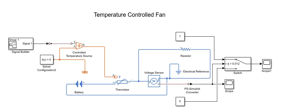
Using the following blocks the temperature controlled fan model was created
- Signal Builder
- Simulink-PS Converter
- PS-Simulink Converter
- Controlled tempterature source
- Solver configuration
- Thermal reference
- Battery
- Thermistor
- Voltage Sensor
- Electrical Reference
- Resistor
- Switch
- Scope
Model
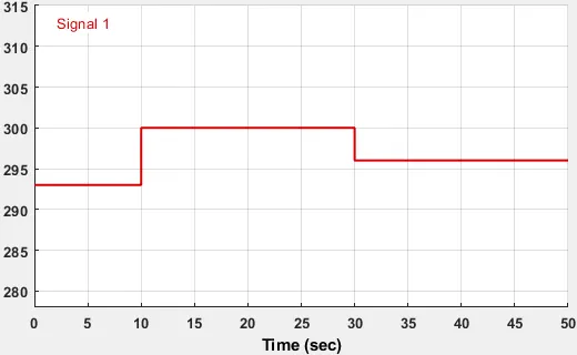
The Temperature Input provided to the signal builder is shown below
0-10sec: Temperature is 20 °C or 293k
10-30: Temperature is 27 °C or 300k
30-50: Temperature is 23 °C or 296k
Fig: Temperature Input
A voltage sensor is connected in paraller to a resistor of 1 ohm to sense the voltage change in the circuit w.r.t the change in the temperature captured by the thermistor which is shown in the fig below
Fig: Voltage Sensor Output
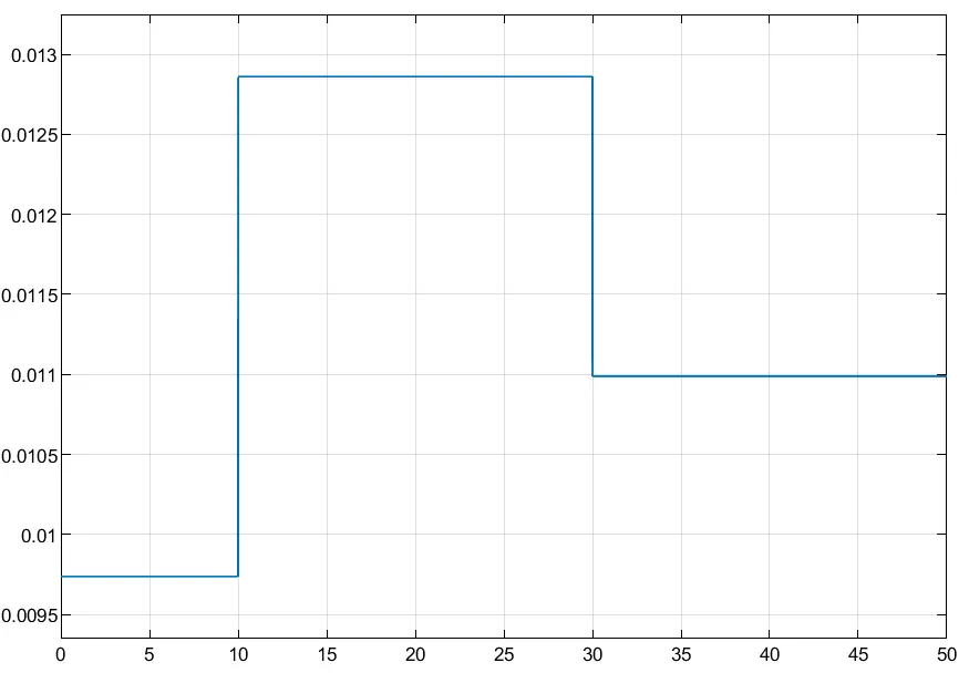
The condition for the fan to switch ON is if the temperature is above 25 °C else the fan is OFF. So checking the equivalent voltage in the voltage sensor output at 25 °C we got 0.012V
So, for the switch block the condition provided to turn on the switch is Threhold Value > 0.012. The output of the switch block is shown in the fig below.
Fig: Switch Output Signal
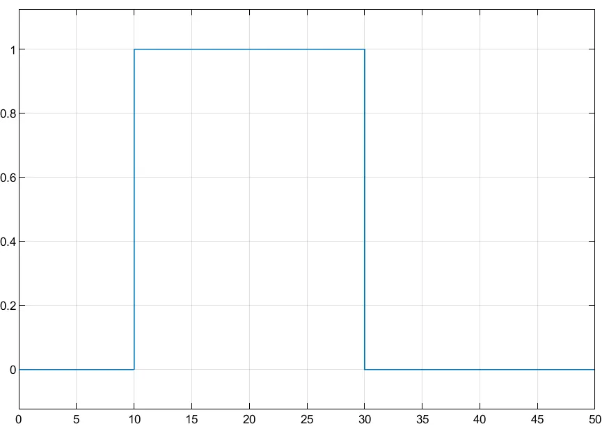
Observation: when the input temperature goes beyond the 25°C at 10sec the voltage signal to the switch block rises above the threshold value and the switch turns on giving signal value of 1, and remains in that position till 30sec, post which the temperature of reduces to 23°C thereby the voltage falls below the threshold and the singal value of the switch changes to 0.
The final output signal from this system can be fed to the fan controls to switch on and off the fan motor