Simulation of Washing Machine and Gear Transmission Control Logic using SIMULINK
SIMULATION OF WASHING MACHINE AND GEAR TRANSMISSION CONTROL LOGIC USING SIMULINK :-
AIM :-
To make a Simulink model of Washing Machine and Gear Shifting control logics.
PLATFORM USED :-
- Software – Simulink (MATLAB)
- Version – R2020a
SYSTEM SPECIFICATIONS :-
- Manufacturer - DELL
- Model – Vostro 3478
- Operating System - Windows 10
- Processor - Intel(R) Core(TM) i5-8250U CPU @ 1.60GHz 1.80GHz
- RAM – 8 GB
OBJECTIVES :-
- Generate a Simulink model to Washing Machine at various states.
- Generate a Simulink model to Shift the Gear according to input speed.
GENERATE A SIMULINK MODEL TO WASHING MACHINE AT VARIOUS STATES
INTRODUCTION :-
The Washing Machine is a machine were many operations are done within a short time period. It performs the operations like soaking, washing, rinsing and drying the clothes w.r.t to the time programmer control which is inbuilt.
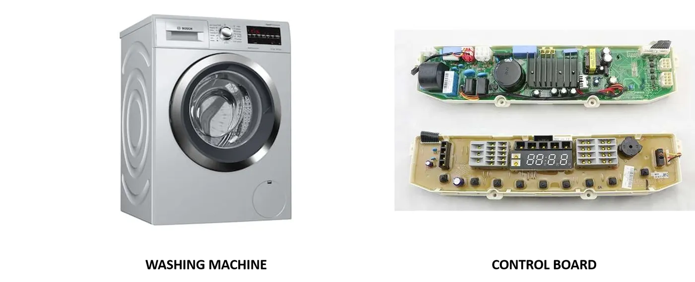
OPERATIONS PERFORMED :-
- Soaking – 200 sec (0-200 sec)
- Washing – 100 sec (200-300 sec)
- Rinsing – 20 sec (300-320 sec)
- Drying – 50 sec (320-370 sec)
- Power OFF – After Drying (>370 sec)
BLOCKS USED :-
- Constant – Power and Water Supply
- Toggle Switch – Determine the output
- Lamp – Indicate the signals
- State Flow – Control Logic
- Muff – Converge the signals for display
- Display – Display the outputs of the states
SIMULINK MODEL :-
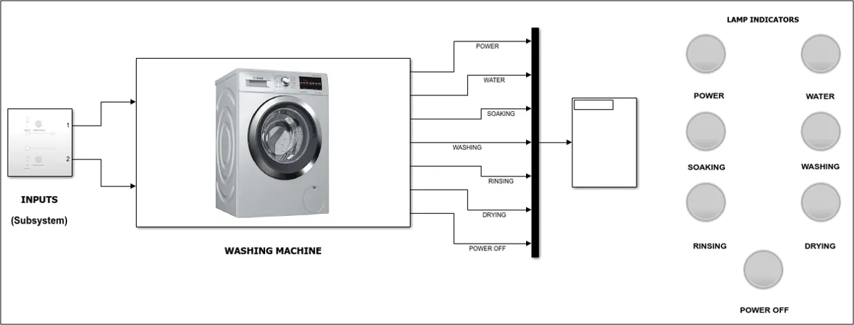
MAIN SYSTEM,
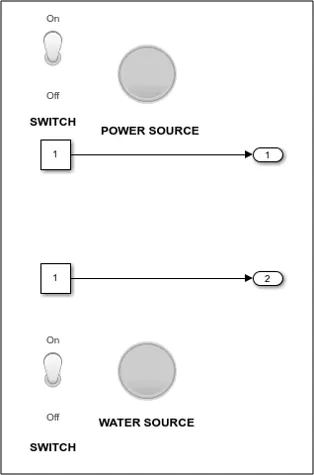
SUBSYSTEM,
STATEFLOW MODEL :-
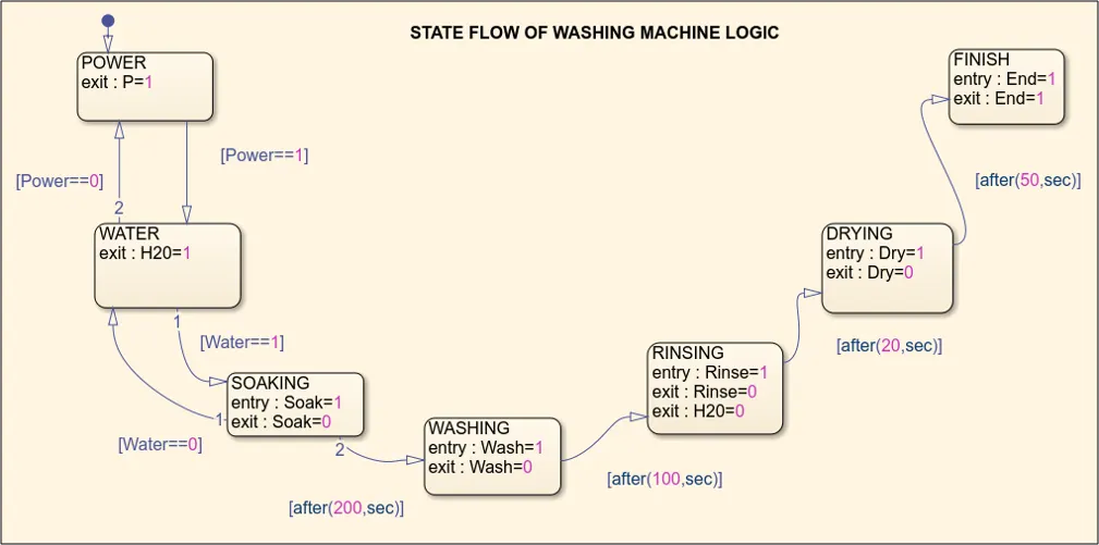
FLOW PROCESS :-
- The power and water supply are defined by constant valued ‘0’ and ‘1’ (OFF & ON).
- Then the toggle switch and lamp activates accordingly to the input.
- The signals get into the state flow model where if Power and Water are ‘1’ it will start the process of washing machine, If the Power and Water are ‘1’ and ‘0’ it will not start the process.
- If Power and Water are ‘1’ the Soaking process will start and after 200 sec Washing process will start.
- After 300 sec Rinsing process will start, after 320 sec Drying process will start along with water supply will cut OFF.
- Finally the washing machine will turn OFF after 370 sec.
- After 370 sec the finish lamp indicates that all the process are completed.
- According to the states the display and lights will indicate the user for better understanding.
CONDITION I – BOTH WATER AND POWER SUPPLY :-
In this process both power and water supply are provided.
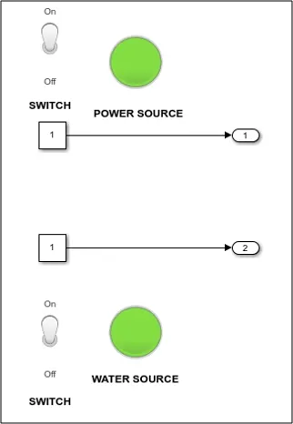
As both the supply are provided so the system gets activated.
SOAKING STATE,
As the system gets activated the soaking process starts which is being continued till 200 sec.
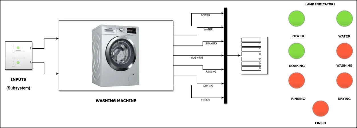
WASHING STATE,
After 200 sec the washing process gets initiated which is being continued till 300 sec.
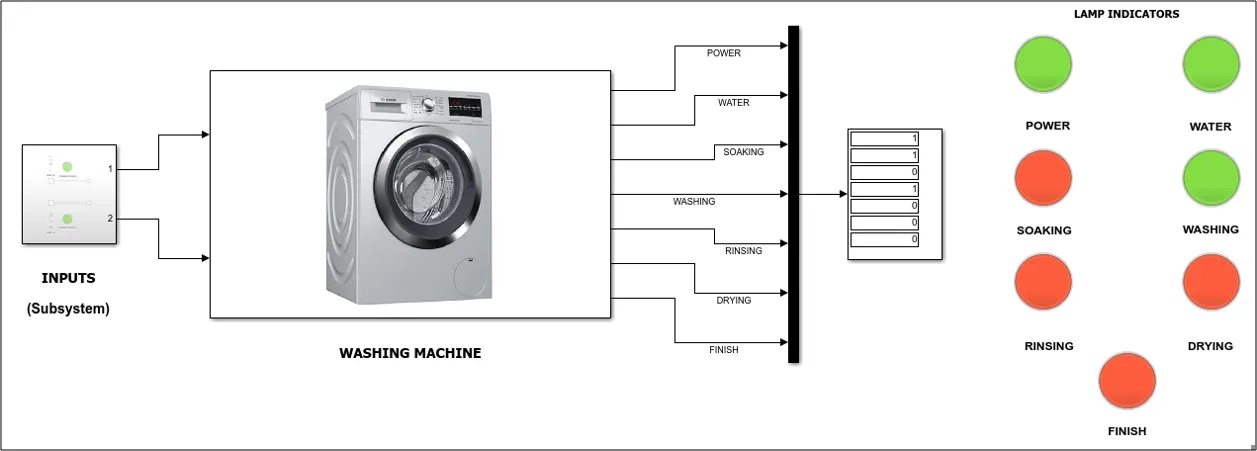
RINSING STATE,
After 300 sec the rinsing process gets initiated which is being continued till 320 sec.
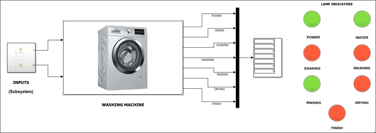
DRYING STATE,
After 320 sec the drying process gets initiated which is being continued till 370 sec. And once the rinsing stage is crossed the water supply is cut off because for drying it’s not required.
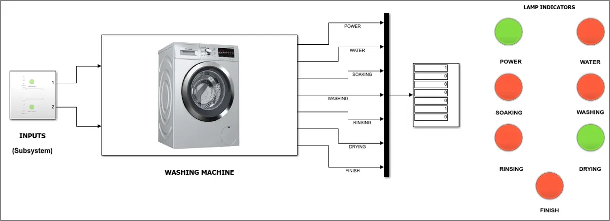
FINISH STATE,
After all the process are completed the washing machine will not take any more water or power to wash the clothes until the user unloads the washed clothes and loads the clothes to be washed. So the finish lamp indicates that the washing cycle is complete.
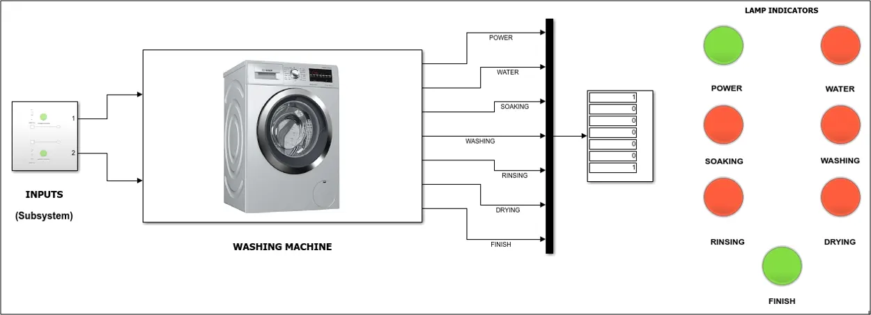
RESULTS :-
The washing machine ran successfully by completing all the process so that the clothes are ready for drying under the sun.
CONDITION II – NO WATER SUPPLY:-
In this process only power supply is provided and the water supply is turned OFF.
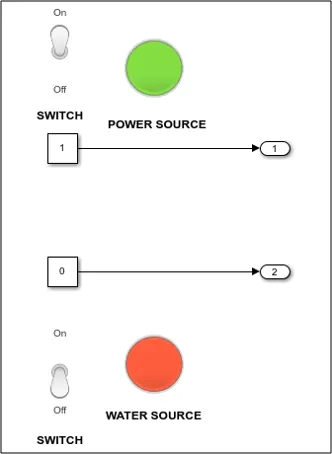
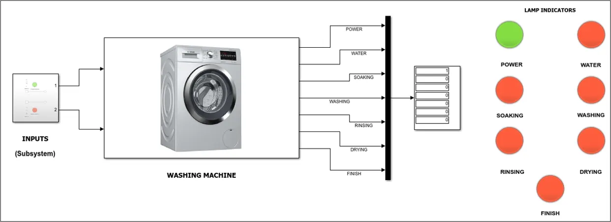
As the water supply is turned OFF the washing machine didn’t start the process cycle. Only the power supply lamp is blinking.
RESULT :-
As the water supply is turned OFF the washing machine didn’t start the process.
CONDITION III – NO POWER AND WATER SUPPLY :-
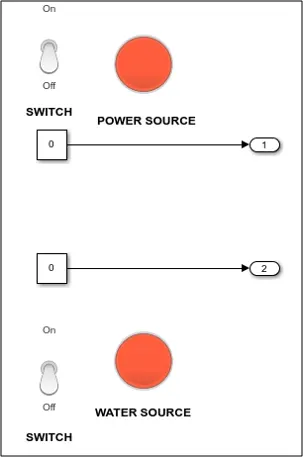
In this process both water and power supply is turned OFF.
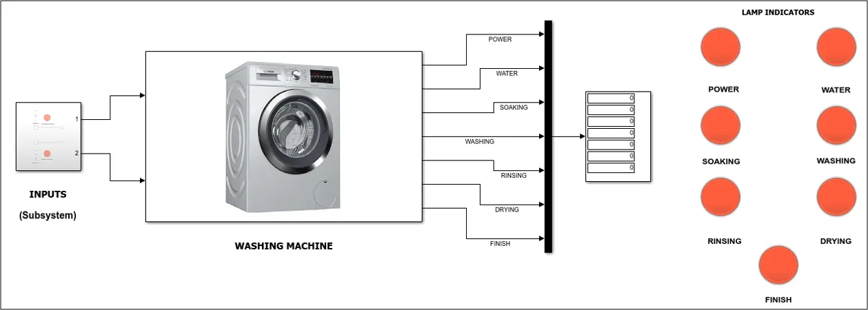
RESULT :-
As both the supplies are turned OFF the washing machine will not function.
GENERATE A SIMULINK MODEL TO SHIFT THE GEAR ACCORDING TO INPUT SPEED
INTRODUCTION :-
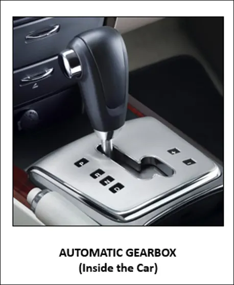
In this model we are simulating automatic gear shifting w.r.t the input speed given by the driver. An automatic transmission uses sensors to determine when it should shift gears, and changes them using internal oil pressure. The system uses a fluid coupling in place of friction clutch, and accomplishes gear changes by hydraulically locking and unlocking a system of planetary gears. As we push the throttle to speed up, the fluid moves the turbine faster to send more power through the transmission.

OPERATIONS PERFORMED :-
- 1st Gear – (0-15 Kmph)
- 2nd Gear – (15-25 Kmph)
- 3rd Gear – (25-40 Kmph)
- 4th Gear – (40-60 Kmph)
- 5th Gear – (>60 Kmph)
BLOCKS USED :-
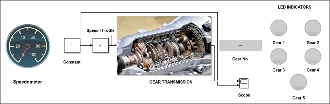
- Constant – To multiply with the slider value
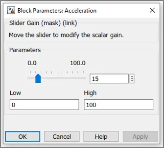
- Slider Gain – To act as throttle to increase the speed
- Lamp – Indicate the Gear Number
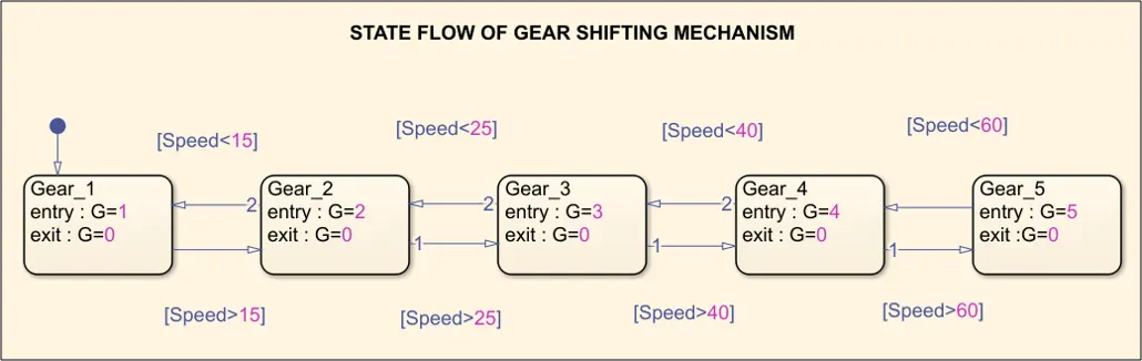
- State Flow – Shifting Logic
- Scope – To view the plot of speed vs gear shift
- Custom Gauge – Speedometer of the vehicle
NOTE – The top speed of the vehicle is considered as 100 Kmph and the simulation time is given as 'inf'.
SIMULINK MODEL :-
STATEFLOW MODEL :-
FLOW PROCESS :-
- Initially the slider value will be ‘0’.
- When we increase the speed the input is given to the state flow chart where it checks the input speed and displays the gear number.
- Here for simulation purpose we had considered the vehicle top speed it 100 Kmph.
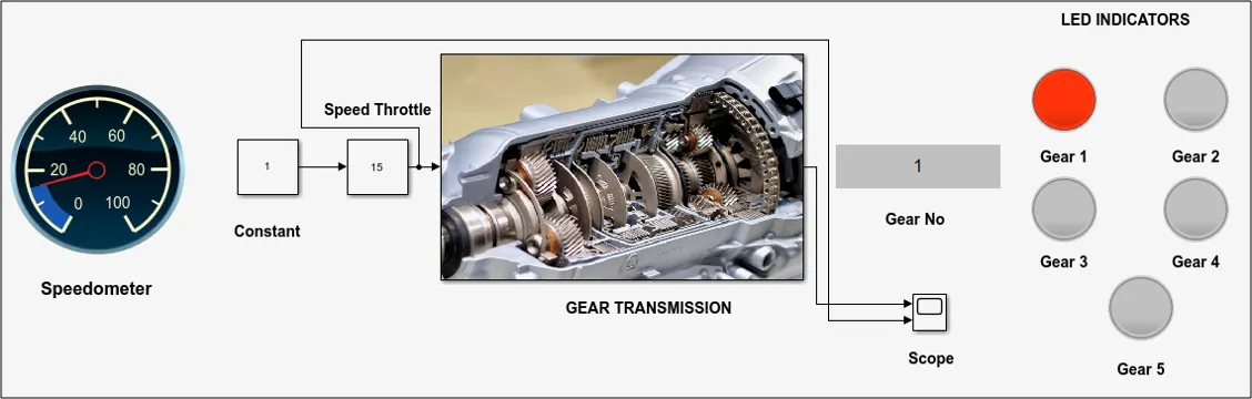
- When the speed is between (0-15 Kmph) the 1st gear gets activated.
- When the speed is between (15-25 Kmph) the 2nd gear gets activated.
- When the speed is between (25-40 Kmph) the 3rd gear gets activated.
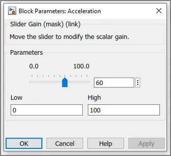
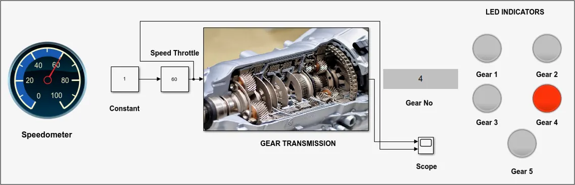
- When the speed is between (40-60 Kmph) the 4th gear gets activated.
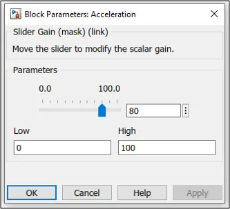
- When the speed is between (61-100 Kmph) the 5th gear gets activated.
- As the speed is increased, decreased or vice-versa we can see the changes in the speedometer.
- We can reduce the gear by decreasing the speed of the vehicle.
RESULTS :-
1st GEAR :-
The first gear is activated till 15 Kmph.
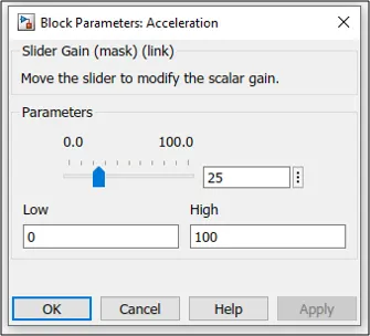
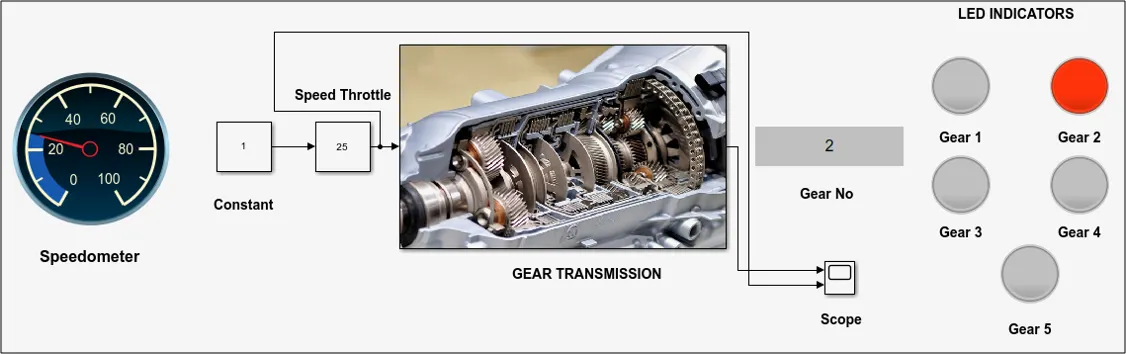
2nd GEAR :-
The second gear is activated from 15-25 Kmph.
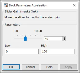
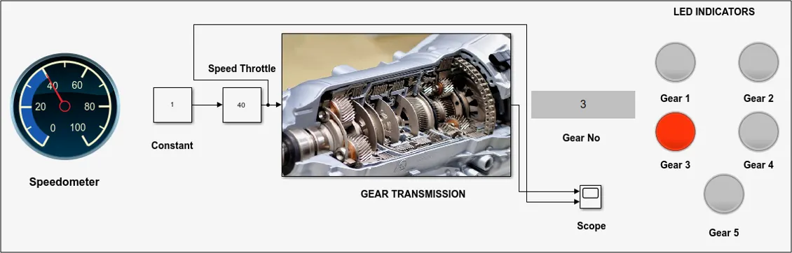
3rd GEAR :-
The third gear is activated from 25-40 Kmph.
4th GEAR :-
The fourth gear is activated from 40-60 Kmph.
5th GEAR :-
The fifth gear is activated above 60 Kmph.
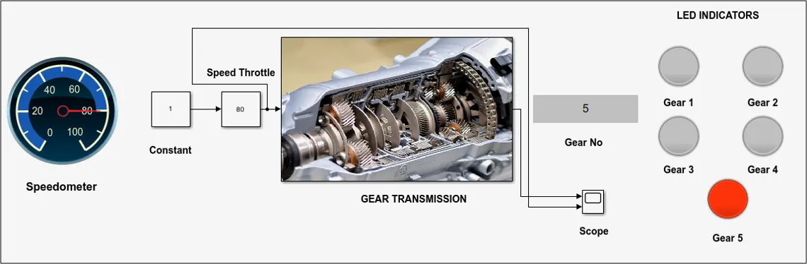
All the gear are activated according to the throttle speed given by the driver as input.
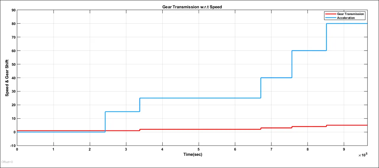
SPEED vs GEAR SHIFT :-
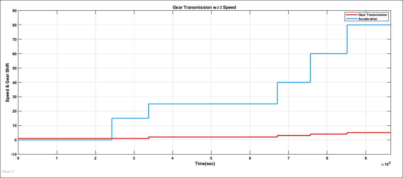
From the above graph we can study that the gears are shifted according to the speed input.
SIMULINK MODEL :-
CONCLUSION :-
The simulation of Washing Machine and Gear Transmission system was completed successfully and the outputs were generated.