Simulation of Flow through a pipe in OpenFoam
Aim:
To conduct an axi-symmetric flow by applying the wedge boundary condition and validate the obtained results with Hagen-Poiseuille's equation for the fully developed flow using MATLAB and OpenFoam.
Objectives:
- To simulate an axi-symmetric flow by applying the wedge boundary condition.
- To conduct the simulation by assuming that the flow is laminar and it flows through a pipe with constant cross section has the reynolds number of 2100 at inlet.
- To validate the results with Hagen-Poiseuille's equations for the fully developed flow.
- To write a code in MATLAB for generating the blockMeshDict file automatically.
- To validate the numerical results with the Hydro-dynamic length.
- To validate the fully developed flow velocity profile with its analytical profile.
- To validate maximum velocity and pressured drop for fully developed flow.
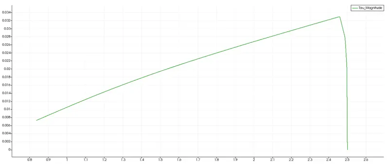
- To Post-process Shear stress and validate wall shear stress for fully developed flow.
Axi-symmetric flow:
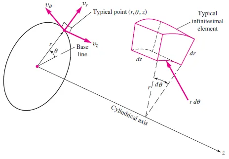
The axi-symmetric flow is defined as a flow pattern in which the flow pattern is identical in every plane that passes through certain straight line. The continuity equation for axi-symmetric flow with cylindrical coordinates is,
`1/r((del(ru_r))/(delr))+(del(u_z))/(delz)=0`
Moreover, the vertices points of the wedge is obtained from the cylindrical coordinates of axi-symmetric flow.
Laminar flow:
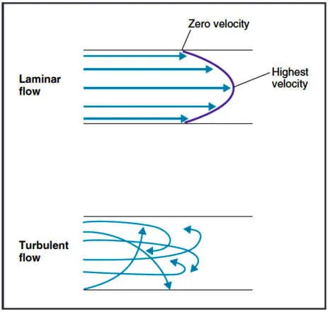
Laminar flow is a type of fluid flow in which the fluid travels smoothly or in regular path. Sometimes, the laminar flow is considered as streamline flow in which the pressure, velocity and other flow properties at each point of the fluid remains constant. The Reynolds number define the character of the flow whether it is laminar or turbulent. The reynolds number lies below 2300 for laminar flow and lies above 2900 for turbulent flow for the fully developed flow condition.
Hydrodynamic entrance length :
The entrance length is defined as the distance a flow travels before developed into a fully developed flow when it enters into a pipe. The entry region corresponds to the expansion of boundary layer. The boundary layer is the layer of fluid in the immediate vicinity of the bounding surface where the effects of viscosity are significant. The hydrodynamic length is defined as the formation of velocity profile caused by the viscous force propagation of pipe wall. Initially, the fluid enters the pipe with constant velocity and once the fluid particles comes in contact with the surface layer of the pipe, it will come to stop due to no slip condition. The velocity profile unchanged in the fully developed region. For the laminar flow, the hydrodynamic fully developed velocity profile is given as,
`(delu(r,x))/(delx)=0`
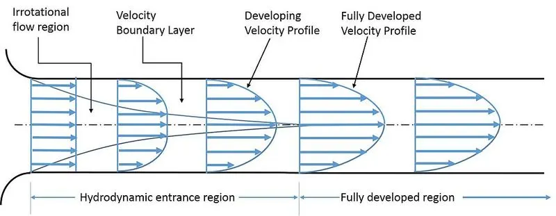
The length of the hydrodynamic entry region along the pipe is called hydrodynamic entry length. It is obtained as the function of reynolds number and diameter of the pipe.
For laminar flow, `L_h,_(laminar) = 0.05R_eD`
where,
`L_h,_(laminar)` is the hydrodynamic entry length for laminar flow,
`R_e` is the Reynolds number,
D is the diameter of the pipe.
Hagen-Poiseuilles equation:
The Hagen-poiseuilles equation is a physical law that gives the pressure drop of the fluid flow. It can be achieved with some assumption. The fluid that flows should be incompressible and Newtonian fluid. It gives the pressure drop where the fluid flow is laminar through a long cylindrical pipe of constant cross section. There should be no acceleration of fluid in the pipe. It depicts the pressure drop due to the viscosity of the fluid. The pressure drop Hagen-Poiseuilles equation is derived from the Navier-stokes continuity equation of the axi-symmetric flow condition.
`DeltaP = (8muLQ)/(piR^4)` `=> 1`
where,
`Delta P` is the pressure difference,
`mu` is the dynamic viscosity,
L is the length of the pipe,
Q is the volumetric flow rate,
R is the radius of the pipe.
we know,
`Q = A*V_(avg)`
A = area of the pipe.
By substituting it in equation 1,
`DeltaP =( 8muLAV_(avg))/(piR^4)`
here, `A = piR^2`
`=> DeltaP = (8muLV_(avg))/R^2`
By multiplying and divided by 4,
`=> DeltaP = (32muLV_(avg))/(4R^2)`
we know,
D = 2R,
`DeltaP=(32muLV_(avg))/(D^2)` `=> 2`
Equations and assumption :
- Assume that the diameter of the pipe, D = 0.02m
- Assume the fluid is water at `25^0`C, so `rho = 997 (kg)/m^3`
- Assume Reynolds number, Re = 2100
- Wedge angle, `theta` = 3 < 5
- Entrance length, `L_e = 0.05ReD`
- Total length, `L_t = L_e +0.4`
- Average velocity, `V_(avg) = (Re*mu)/(rho*D)`
- Maximum velocity, `V_max = 2*V_(avg)`
- Kinematic pressure, `P_k = (DeltaP)/(rho)`
- shear stress, `tau = (2*mu*V_max*Rad_(distance))/(R^2)`
Using several conditiond and assumptions, values for various parameters and blockMesh Dict file are made in MATLAB using file file parsing technique.
Pre-processing steps:
- Initially, various parameters and values are initialized in the MATLAB for finding the theoretical value.
- The vertices are found using the various assumptions.
- The blockMesh Dict file is easily made from MATLAB for various wedge angles.
- Now, the openFoam software is opened through terminal and tutorial folder is opened.
- Inside the tutorial folder, incompressible folder is opened and then icoFoam solver is selected.
- The two successive cavity folders are opened and it was stored in the $FOAM_RUN folder.
- Inside the copied folder, system folder is opened and the blockMesh Dict file is changed based on the MATLAB file.
- The control dict file in the system folder is also altered for conducting the simulation for required time.
- In the control dict file end time is assumed as 50 with the with write interval 200 and `delt` is 0.01.
MATLAB code:
clear all
close all
clc

%Flow through pipe using MATLAB and OpenFoam

%Initializing the values
%Diameter of pipe
D = 0.02;

%Reynolds number
Re = 2100;

%Dynamic viscosity
mu = 0.00089;

%Density
density = 997;

%Hydrodynamic entrance length
L_e = 0.05*Re*D;

%Total length of pipe
L_t = L_e + 0.4;

%wedge angle
theta = 3;

%Radius of the pipe
r = D/2;

%Average velocity and maximum velocity
V_avg = (Re*mu)/(density*D);
V_max = 2*V_avg;

%Hagen-Poiseuille equations
%Pressure drop
del_P = (8*mu*L_e*V_avg)/(r^2);

%Kinematic pressure
kin_P = del_P/density;

%Radial distance for shear stress calculation
R_dis = linspace(0,r,1000);

%Shear stress calculation
for i=1:length(R_dis)
    Tau_wall = (2*mu*V_max*R_dis)/(r^2);
end

%blockMesh dict file

%Vertices
v_0 = [0 0 0];
v_1 = [0 r*cosd(theta/2) -r*sind(theta/2)];
v_2 = [0 r*cosd(theta/2) r*sind(theta/2)];
v_3 = [L_t 0 0];
v_4 = [L_t r*cosd(theta/2) -r*sind(theta/2)];
v_5 = [L_t r*cosd(theta/2) r*sind(theta/2)];

%Initializing the header files
h1 = '/*--------------------------------*- C++ -*----------------------------------*';
h2 = '=========                 |';
h3 = '      /  F ield         | OpenFOAM: The Open Source CFD Toolbox';
h4 = '     /   O peration     | Website:  https://openfoam.org';
h5 = '    /    A nd           | Version:  8';
h6 = '   /     M anipulation  |';
h7 = '*---------------------------------------------------------------------------*/';

%Opening the blockMeshDict file named as f1
f1 = fopen('blockMeshDict','w');

fprintf(f1, '%sn', h1);
fprintf(f1, '%sn', h2);
fprintf(f1, '%sn', h3);
fprintf(f1, '%sn', h4);
fprintf(f1, '%sn', h5);
fprintf(f1, '%sn', h6);
fprintf(f1, '%sn', h7);

fprintf(f1, '%sn', 'FoamFile');
fprintf(f1, '%sn', '{');
fprintf(f1, '%sn', '    version     2.0;');
fprintf(f1, '%sn', '    format      ascii;');
fprintf(f1, '%sn', '    class       dictionary;');
fprintf(f1, '%sn', '    object      blockMeshDict;');
fprintf(f1, '%sn', '}');
fprintf(f1, '%snn', '// * * * * * * * * * * * * * * * * * * * * * * * * * * * * * * * * * * * * * //');

fprintf(f1, '%snn', 'convertToMeters 1;');

%Vertices
fprintf(f1, '%sn', 'vertices');
fprintf(f1, '%snn', '(');
fprintf(f1, 't(%d %d %d)n',v_0);
fprintf(f1, 't(%d %d %d)n',v_1);
fprintf(f1, 't(%d %d %d)n',v_2);
fprintf(f1, 't(%d %d %d)n',v_3);
fprintf(f1, 't(%d %d %d)n',v_4);
fprintf(f1, 't(%d %d %d)n',v_5);
fprintf(f1, '%snn', ');');

%blocks
fprintf(f1, '%sn', 'blocks');
fprintf(f1, '%snn', '(');
b_1 = 50;
b_2 = 1;
b_3 = 200;
fprintf(f1, '    hex (0 1 2 0 3 4 5 3) (%d %d %d) simpleGrading (0.2 1 1)nn',b_1,b_2,b_3);
fprintf(f1, '%snn', ');');

%Edges
fprintf(f1, '%sn', 'edges');
fprintf(f1, '%snn', '(');
fprintf(f1, 't arc %d %d (%d %d %d)n',1,2,0,r,0);
fprintf(f1, 't arc %d %d (%d %d %d)n',4,5,L_t,r,0);
fprintf(f1, '%snn', ');');

%Boundaries
fprintf(f1, '%sn', 'boundary');
fprintf(f1, '%snn', '(');

%Inlet condition
fprintf(f1, '%sn', '    inlet');
fprintf(f1, '%sn', '    {');
fprintf(f1, '%sn', '        type patch;');
fprintf(f1, '%sn', '        faces');
fprintf(f1, '%sn', '        (');
fprintf(f1, '%sn', '            (0 1 2 0)');
fprintf(f1, '%sn', '        );');
fprintf(f1, '%sn', '    }');

%Outlet condition
fprintf(f1, '%sn', '    outlet');
fprintf(f1, '%sn', '    {');
fprintf(f1, '%sn', '        type patch;');
fprintf(f1, '%sn', '        faces');
fprintf(f1, '%sn', '        (');
fprintf(f1, '%sn', '            (3 4 5 3)');
fprintf(f1, '%sn', '        );');
fprintf(f1, '%sn', '    }');

%Top face of blockMesh
fprintf(f1, '%sn', '    top');
fprintf(f1, '%sn', '    {');
fprintf(f1, '%sn', '        type patch;');
fprintf(f1, '%sn', '        faces');
fprintf(f1, '%sn', '        (');
fprintf(f1, '%sn', '            (1 2 5 4)');
fprintf(f1, '%sn', '        );');
fprintf(f1, '%sn', '    }');

%Front face of blockMesh
fprintf(f1, '%sn', '    front');
fprintf(f1, '%sn', '    {');
fprintf(f1, '%sn', '         type wedge;');
fprintf(f1, '%sn', '        faces');
fprintf(f1, '%sn', '        (');
fprintf(f1, '%sn', '            (0 3 5 2)');
fprintf(f1, '%sn', '        );');
fprintf(f1, '%sn', '    }');

%Back face of blockMesh
fprintf(f1, '%sn', '    back');
fprintf(f1, '%sn', '    {');
fprintf(f1, '%sn', '         type wedge;');
fprintf(f1, '%sn', '        faces');
fprintf(f1, '%sn', '        (');
fprintf(f1, '%sn', '            (0 3 4 1)');
fprintf(f1, '%sn', '        );');
fprintf(f1, '%sn', '    }');
fprintf(f1, '%sn', ');');

fprintf(f1, '%sn', 'mergePatchPairs');
fprintf(f1, '%sn', '(');
fprintf(f1, '%sn', ');');

fprintf(f1, '%sn', '// ************************************************************************* //');
fclose(f1);
BlockMeshDict file:
The blockMesh dict file in the system folder is altered using the MATLAB code shown above.
/*--------------------------------*- C++ -*----------------------------------*
  =========                 |
        /  F ield         | OpenFOAM: The Open Source CFD Toolbox
       /   O peration     | Website:  https://openfoam.org
      /    A nd           | Version:  8
     /     M anipulation  |
*---------------------------------------------------------------------------*/
FoamFile
{
    version     2.0;
    format      ascii;
    class       dictionary;
    object      blockMeshDict;
}
// * * * * * * * * * * * * * * * * * * * * * * * * * * * * * * * * * * * * * //

convertToMeters 1;

vertices
(
    (0 0 0)
    (0 0.009996573249756 -2.617694830787316e-04)
    (0 0.009996573249756 2.617694830787316e-04)
    (2.500000000000000 0 0)
    (2.500000000000000 0.009996573249756 -2.617694830787316e-04)
    (2.500000000000000 0.009996573249756 2.617694830787316e-04)

);

blocks
(
    hex (0 1 2 0 3 4 5 3) (50 1 200) simpleGrading (0.2 1 1)
);

edges
(
    arc 1 2 (0 0.010000000000000 0)
    arc 4 5 (2.500000000000000 0.010000000000000 0)
);

boundary
(
    inlet
    {
        type patch;
        faces
        (
            (0 1 2 0)
        );
    }
    outlet
    {
        type patch;
        faces
        (
            (3 4 5 3)

        );
    }
    top
    {
        type patch;
        faces
        (
            (1 2 5 4)

        );
    }
    front
    {
        type wedge;
        faces
        (
            (0 3 5 2)
        );
    }
    back
    {
        type wedge;
        faces
        (
            (0 3 4 1)

        );
    }
);

mergePatchPairs
(
);

// ************************************************************************* //
Control Dict file :
/*--------------------------------*- C++ -*----------------------------------*
  =========                 |
        /  F ield         | OpenFOAM: The Open Source CFD Toolbox
       /   O peration     | Website:  https://openfoam.org
      /    A nd           | Version:  8
     /     M anipulation  |
*---------------------------------------------------------------------------*/
FoamFile
{
    version     2.0;
    format      ascii;
    class       dictionary;
    location    "system";
    object      controlDict;
}
// * * * * * * * * * * * * * * * * * * * * * * * * * * * * * * * * * * * * * //

application     icoFoam;

startFrom       startTime;

startTime       0;

stopAt          endTime;

endTime         50;

deltaT          0.01;

writeControl    timeStep;

writeInterval   200;

purgeWrite      0;

writeFormat     ascii;

writePrecision  6;

writeCompression off;

timeFormat      general;

timePrecision   6;

runTimeModifiable true;


// ************************************************************************* //
Boundary condition:
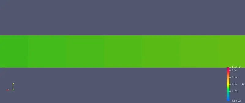
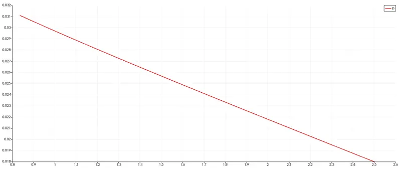
The pressure boundary condition is assigned by editing the '0' folder. In this simulation, the outlet of the wedge is initialized as fixed value of 0.018. The inlet and top face is initialized with zeroGradient.
The velocity boundary condition is assigned by editing the '0' folder. In this simulation, the velocity of 0.0937312 is assigned along the x-axis. The top face is assigned with the fixed value of (0 0 0).
Pressure file:
/*--------------------------------*- C++ -*----------------------------------*
  =========                 |
        /  F ield         | OpenFOAM: The Open Source CFD Toolbox
       /   O peration     | Website:  https://openfoam.org
      /    A nd           | Version:  8
     /     M anipulation  |
*---------------------------------------------------------------------------*/
FoamFile
{
    version     2.0;
    format      ascii;
    class       volScalarField;
    object      p;
}
// * * * * * * * * * * * * * * * * * * * * * * * * * * * * * * * * * * * * * //

dimensions      [0 2 -2 0 0 0 0];

internalField   uniform 0;

boundaryField
{
    axis
    {
        type            empty;
    }

    inlet
    {
        type            zeroGradient;
    }

    outlet
    {
        type            fixedValue;
        value           uniform 0.018;
    }

    top
    {
        type            zeroGradient;
    }

    front
    {
        type            wedge;
    }

    back
    {
        type            wedge;
    }
}

// ************************************************************************* //
Velocity file:
/*--------------------------------*- C++ -*----------------------------------*
  =========                 |
        /  F ield         | OpenFOAM: The Open Source CFD Toolbox
       /   O peration     | Website:  https://openfoam.org
      /    A nd           | Version:  8
     /     M anipulation  |
*---------------------------------------------------------------------------*/
FoamFile
{
    version     2.0;
    format      ascii;
    class       volVectorField;
    object      U;
}
// * * * * * * * * * * * * * * * * * * * * * * * * * * * * * * * * * * * * * //

dimensions      [0 1 -1 0 0 0 0];

internalField   uniform (0.0937312 0 0);

boundaryField
{
    axis
    {
        type            empty;

    }

    inlet
    {
        type            fixedValue;
        value           uniform (0.0937312 0 0);
    }

    outlet
    {
        type            zeroGradient;
    }

    top
    {
        type            fixedValue;
        value           uniform (0 0 0);
    }

    front
    {
        type            wedge;

    }

    back
    {
        type            wedge;

    }

}

// ************************************************************************* //
Transport properties:
/*--------------------------------*- C++ -*----------------------------------*
  =========                 |
        /  F ield         | OpenFOAM: The Open Source CFD Toolbox
       /   O peration     | Website:  https://openfoam.org
      /    A nd           | Version:  8
     /     M anipulation  |
*---------------------------------------------------------------------------*/
FoamFile
{
    version     2.0;
    format      ascii;
    class       dictionary;
    location    "constant";
    object      transportProperties;
}
// * * * * * * * * * * * * * * * * * * * * * * * * * * * * * * * * * * * * * //

nu              [0 2 -1 0 0 0 0] 1e-06;


// ************************************************************************* //
Geometry:
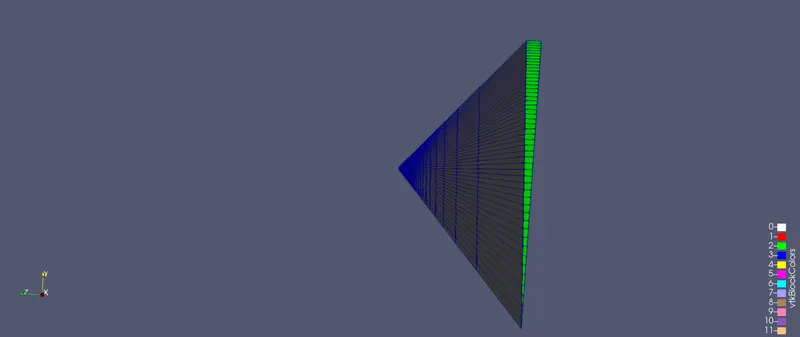
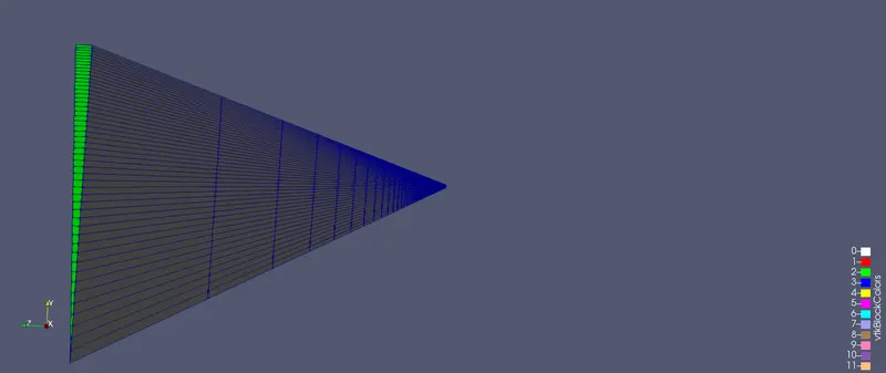
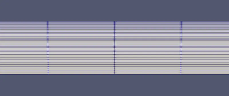
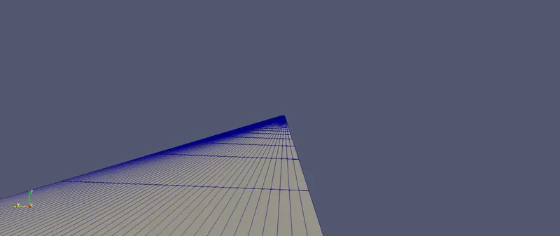
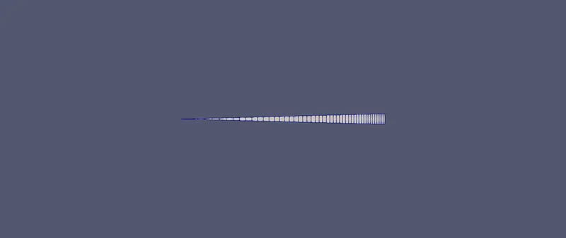
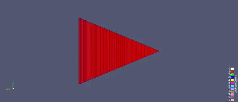
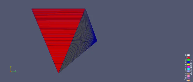
The geometry is created based on the values in the blockMesh dict file. The grading was done at each axis accurately.
Post processing steps :
- The boundary conditions are initialized in the p and U file present in the '0' folder.
- The transport properties file in the constant folder is also edited.
- Then, icoFoam command is used to run the simulation.
- After the end of simulation, paraFoam command is used to visualise the results.
- The velocity and pressure profiles are visulaised by color the geometry by respective parameters.
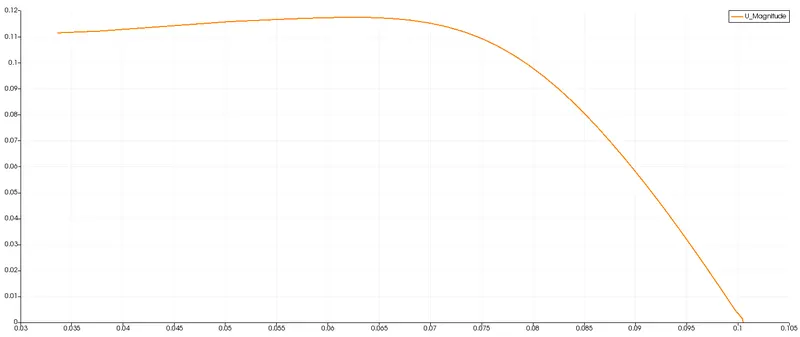
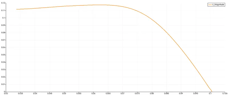
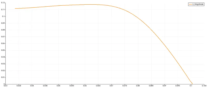
- The line probe is fixed in particular distance to view the velocity graphs.
- The changes in the velocity can be seen by obtaining the graph at various distance of the pipe length.
- The pressure along the length of the pipe is also plotted.
- The wall shear stress value along radial distance is plotted.
- The results are analysed with the theoretical results.
Velocity profile :
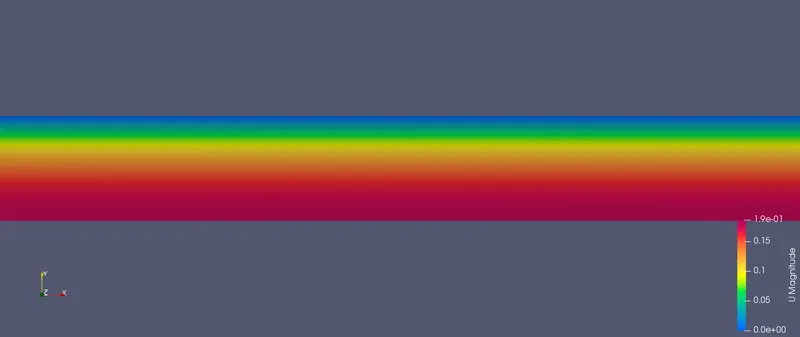
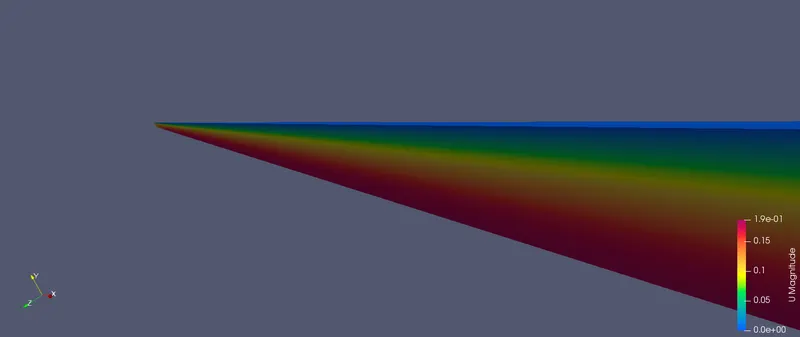
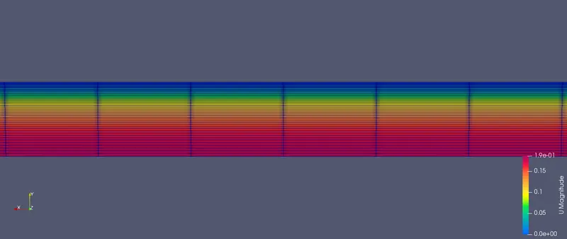
Pressure profile :
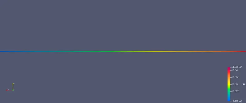
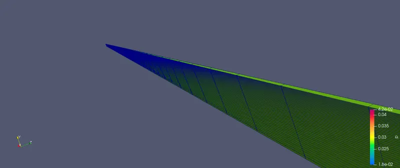
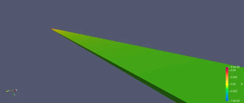
Velocity profile (Graphical):
1. Velocity at a distance of 0.1:
2. Velocity at a distance of 0.5:
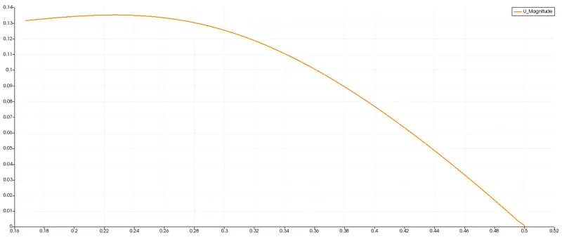
3. Velocity at a distance of 1:
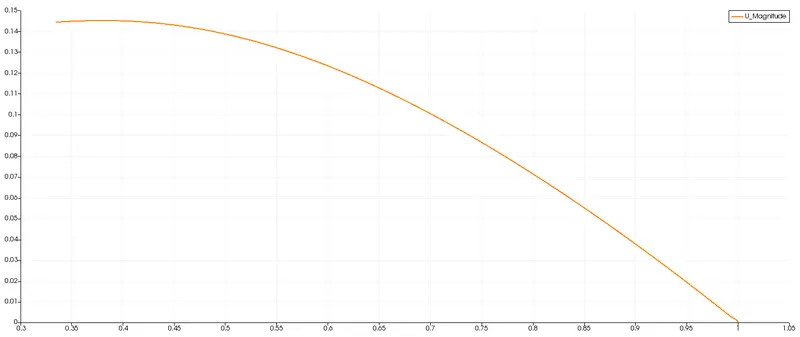
4. Velocity at a distance of 1.5:
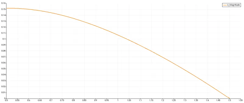
5. Velocity at a distance of 2.5:
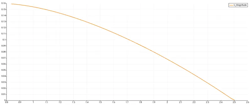
Pressure profile (Graphical) :
Wall shear stress :
Results :
1. Courant Number :
Mean - 0.0777296
Max - 0.373296
2. Execution time - 279.56 s
3. Clock time - 317s
4. Hagen-poiseuille's `DeltaP` = 14.014688064192576 N/m^2
5. Maximum theoretical velocity - 0.1875 m/s
6. Maximum computational velocity - 0.158977 m/s
7. Error - 0.02853.
Validation studies of Symmetry BC vs Wedge BC in OpenFOAM vs Analytical H.P equation
Objectives :
- To conduct the simulation with wedge and symmetry boundary condition.
- To conduct the simulation with various wedge angle of `10^0`, `25^0` and `45^0`.
- To edit the blockMesh file by obtaining the vertices points from MATLAB code.
- To validate the results with analytical H.P equation.
Symmetry boundary condition :
The mirror face or surface is defined as the symmetry boundary condition. It is used in a CFD problem in which the geometry or physical object and the expected flow field pattern developed solution are mirrored along that surface. BY using this boundary condition, we can reduce the time to achieve the solution. This boundary condition can be applied in the CFD problem where the fluxes across the symmetry are zero and the normal components of all variables are set to zero. It can be applied in both planar and non-planer surfaces.
Wedge boundary condition :
The axi symmetrical situation in CFD is defined by wedge boundary condition. The wedge boundary condition can be applied with a particular condition in which the model and the flow must be axi symmetric along the central line such that all physical variables of the flow have the same value and distribution at given radius for all angles. It is specified in two planes that must be selected on separate side of the domain. The wedge BC is different when compared with symmetry BC. The wedge boundary condition can be applied in the navier stokes equation in the cylindrical coordinates and symmetry boundary condition applies in cartesian coordinates.
BlockMesh Dict file :
The blockMesh dict file can be defined for various wedge angle of `10^0`, `25^0` and `45^0` using the MATLAB code.
clear all
close all
clc

%Flow through pipe using MATLAB and OpenFoam

%Initializing the values
%Diameter of pipe
D = 0.02;

%Reynolds number
Re = 2100;

%Dynamic viscosity
mu = 0.00089;

%Density
density = 997;

%Hydrodynamic entrance length
L_e = 0.05*Re*D;

%Total length of pipe
L_t = L_e + 0.4;

%wedge angle
theta = 25;

%Radius of the pipe
r = D/2;

%Average velocity and maximum velocity
V_avg = (Re*mu)/(density*D);
V_max = 2*V_avg;

%Hagen-Poiseuille equations
%Pressure drop
del_P = (8*mu*L_e*V_avg)/(r^2);

%Kinematic pressure
kin_P = del_P/density;

%Radial distance for shear stress calculation
R_dis = linspace(0,r,1000);

%Shear stress calculation
for i=1:length(R_dis)
    Tau_wall = (2*mu*V_max*R_dis)/(r^2);
end

%blockMesh dict file

%Vertices
v_0 = [0 0 0];
v_1 = [0 r*cosd(theta/2) -r*sind(theta/2)];
v_2 = [0 r*cosd(theta/2) r*sind(theta/2)];
v_3 = [L_t 0 0];
v_4 = [L_t r*cosd(theta/2) -r*sind(theta/2)];
v_5 = [L_t r*cosd(theta/2) r*sind(theta/2)];

%Initializing the header files
h1 = '/*--------------------------------*- C++ -*----------------------------------*\';
h2 = '=========                 |';
h3 = '\\      /  F ield         | OpenFOAM: The Open Source CFD Toolbox';
h4 = ' \\    /   O peration     | Website:  https://openfoam.org';
h5 = '  \\  /    A nd           | Version:  8';
h6 = '   \\/     M anipulation  |';
h7 = '\*---------------------------------------------------------------------------*/';

%Opening the blockMeshDict file named as f1
f1 = fopen('blockMeshDict','w');

fprintf(f1, '%sn', h1);
fprintf(f1, '%sn', h2);
fprintf(f1, '%sn', h3);
fprintf(f1, '%sn', h4);
fprintf(f1, '%sn', h5);
fprintf(f1, '%sn', h6);
fprintf(f1, '%sn', h7);

fprintf(f1, '%sn', 'FoamFile');
fprintf(f1, '%sn', '{');
fprintf(f1, '%sn', '    version     2.0;');
fprintf(f1, '%sn', '    format      ascii;');
fprintf(f1, '%sn', '    class       dictionary;');
fprintf(f1, '%sn', '    object      blockMeshDict;');
fprintf(f1, '%sn', '}');
fprintf(f1, '%snn', '// * * * * * * * * * * * * * * * * * * * * * * * * * * * * * * * * * * * * * //');

fprintf(f1, '%snn', 'convertToMeters 1;');

%Vertices
fprintf(f1, '%sn', 'vertices');
fprintf(f1, '%snn', '(');
fprintf(f1, 't(%d %d %d)n',v_0);
fprintf(f1, 't(%d %d %d)n',v_1);
fprintf(f1, 't(%d %d %d)n',v_2);
fprintf(f1, 't(%d %d %d)n',v_3);
fprintf(f1, 't(%d %d %d)n',v_4);
fprintf(f1, 't(%d %d %d)n',v_5);
fprintf(f1, '%snn', ');');

%blocks
fprintf(f1, '%sn', 'blocks');
fprintf(f1, '%snn', '(');
b_1 = 50;
b_2 = 1;
b_3 = 200;
fprintf(f1, '    hex (0 1 2 0 3 4 5 3) (%d %d %d) simpleGrading (0.2 1 1)nn',b_1,b_2,b_3);
fprintf(f1, '%snn', ');');

%Edges
fprintf(f1, '%sn', 'edges');
fprintf(f1, '%snn', '(');
fprintf(f1, 't arc %d %d (%d %d %d)n',1,2,0,r,0);
fprintf(f1, 't arc %d %d (%d %d %d)n',4,5,L_t,r,0);
fprintf(f1, '%snn', ');');

%Boundaries
fprintf(f1, '%sn', 'boundary');
fprintf(f1, '%snn', '(');

%Inlet condition
fprintf(f1, '%sn', '    inlet');
fprintf(f1, '%sn', '    {');
fprintf(f1, '%sn', '        type patch;');
fprintf(f1, '%sn', '        faces');
fprintf(f1, '%sn', '        (');
fprintf(f1, '%sn', '            (0 1 2 0)');
fprintf(f1, '%sn', '        );');
fprintf(f1, '%sn', '    }');

%Outlet condition
fprintf(f1, '%sn', '    outlet');
fprintf(f1, '%sn', '    {');
fprintf(f1, '%sn', '        type patch;');
fprintf(f1, '%sn', '        faces');
fprintf(f1, '%sn', '        (');
fprintf(f1, '%sn', '            (3 4 5 3)');
fprintf(f1, '%sn', '        );');
fprintf(f1, '%sn', '    }');

%Top face of blockMesh
fprintf(f1, '%sn', '    top');
fprintf(f1, '%sn', '    {');
fprintf(f1, '%sn', '        type patch;');
fprintf(f1, '%sn', '        faces');
fprintf(f1, '%sn', '        (');
fprintf(f1, '%sn', '            (1 2 5 4)');
fprintf(f1, '%sn', '        );');
fprintf(f1, '%sn', '    }');

%Front face of blockMesh
fprintf(f1, '%sn', '    front');
fprintf(f1, '%sn', '    {');
fprintf(f1, '%sn', '         type wedge;');
fprintf(f1, '%sn', '        faces');
fprintf(f1, '%sn', '        (');
fprintf(f1, '%sn', '            (0 3 5 2)');
fprintf(f1, '%sn', '        );');
fprintf(f1, '%sn', '    }');

%Back face of blockMesh
fprintf(f1, '%sn', '    back');
fprintf(f1, '%sn', '    {');
fprintf(f1, '%sn', '         type wedge;');
fprintf(f1, '%sn', '        faces');
fprintf(f1, '%sn', '        (');
fprintf(f1, '%sn', '            (0 3 4 1)');
fprintf(f1, '%sn', '        );');
fprintf(f1, '%sn', '    }');
fprintf(f1, '%sn', ');');

fprintf(f1, '%sn', 'mergePatchPairs');
fprintf(f1, '%sn', '(');
fprintf(f1, '%sn', ');');

fprintf(f1, '%sn', '// ************************************************************************* //');
fclose(f1);
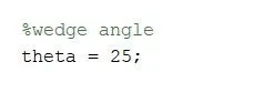
The above MATLAB code is used to generate the blockMesh dict file for wedge angle of `25^0`. Similarly for various angle values, the theta value in the above code can be changed to get the desired blockMesh dict file.
BlockMesh file :
The blockMesh file for angle of `45^0` under symmetry boundary condition is attached below,
/*--------------------------------*- C++ -*----------------------------------*\
  =========                 |
  \\      /  F ield         | OpenFOAM: The Open Source CFD Toolbox
   \\    /   O peration     | Website:  https://openfoam.org
    \\  /    A nd           | Version:  8
     \\/     M anipulation  |
\*---------------------------------------------------------------------------*/
FoamFile
{
    version     2.0;
    format      ascii;
    class       dictionary;
    object      blockMeshDict;
}
// * * * * * * * * * * * * * * * * * * * * * * * * * * * * * * * * * * * * * //

convertToMeters 1;

vertices
(
    (0 0 0)
    (0 0.009238795325113 -0.003826834323651)
    (0 0.009238795325113 0.003826834323651)
    (2.500000000000000 0 0)
    (2.500000000000000 0.009238795325113 -0.003826834323651)
    (2.500000000000000 0.009238795325113 0.003826834323651)

);

blocks
(
    hex (0 1 2 0 3 4 5 3) (50 1 200) simpleGrading (0.2 1 1)
);

edges
(
    arc 1 2 (0 0.010000000000000 0)
    arc 4 5 (2.500000000000000 0.010000000000000 0)
);

boundary
(
    inlet
    {
        type patch;
        faces
        (
            (0 1 2 0)
        );
    }
    outlet
    {
        type patch;
        faces
        (
            (3 4 5 3)

        );
    }
    top
    {
        type patch;
        faces
        (
            (1 2 5 4)

        );
    }
    front
    {
        type symmetry;
        faces
        (
            (0 3 5 2)
        );
    }
    back
    {
        type symmetry;
        faces
        (
            (0 3 4 1)

        );
    }
);

mergePatchPairs
(
);

// ************************************************************************* //
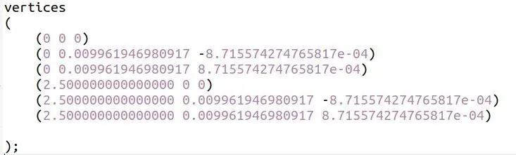
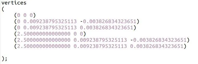
Similarly for various angle the theta value in the MATLAB code was changed and the respective vertices points are obtained. The wedge boundary condition can be applied by replacing the word "symmetry" by "wedge".
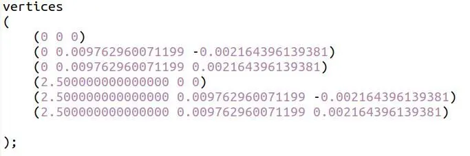
Vertices for angle `10^0` :
Vertices for angle `25^0` :
Vertices for angle `45^0` :
Control dict :
/*--------------------------------*- C++ -*----------------------------------*\
  =========                 |
  \\      /  F ield         | OpenFOAM: The Open Source CFD Toolbox
   \\    /   O peration     | Website:  https://openfoam.org
    \\  /    A nd           | Version:  8
     \\/     M anipulation  |
\*---------------------------------------------------------------------------*/
FoamFile
{
    version     2.0;
    format      ascii;
    class       dictionary;
    location    "system";
    object      controlDict;
}
// * * * * * * * * * * * * * * * * * * * * * * * * * * * * * * * * * * * * * //

application     icoFoam;

startFrom       startTime;

startTime       0;

stopAt          endTime;

endTime         50;

deltaT          0.01;

writeControl    timeStep;

writeInterval   200;

purgeWrite      0;

writeFormat     ascii;

writePrecision  6;

writeCompression off;

timeFormat      general;

timePrecision   6;

runTimeModifiable true;


// ************************************************************************* //
Transport properties :
/*--------------------------------*- C++ -*----------------------------------*\
  =========                 |
  \\      /  F ield         | OpenFOAM: The Open Source CFD Toolbox
   \\    /   O peration     | Website:  https://openfoam.org
    \\  /    A nd           | Version:  8
     \\/     M anipulation  |
\*---------------------------------------------------------------------------*/
FoamFile
{
    version     2.0;
    format      ascii;
    class       dictionary;
    location    "constant";
    object      transportProperties;
}
// * * * * * * * * * * * * * * * * * * * * * * * * * * * * * * * * * * * * * //

nu              [0 2 -1 0 0 0 0] 1e-06;


// ************************************************************************* //
Velocity boundary condition :
/*--------------------------------*- C++ -*----------------------------------*\
  =========                 |
  \\      /  F ield         | OpenFOAM: The Open Source CFD Toolbox
   \\    /   O peration     | Website:  https://openfoam.org
    \\  /    A nd           | Version:  8
     \\/     M anipulation  |
\*---------------------------------------------------------------------------*/
FoamFile
{
    version     2.0;
    format      ascii;
    class       volVectorField;
    object      U;
}
// * * * * * * * * * * * * * * * * * * * * * * * * * * * * * * * * * * * * * //

dimensions      [0 1 -1 0 0 0 0];

internalField   uniform (0.0937312 0 0);

boundaryField
{
    axis
    {
        type            empty;

    }

    inlet
    {
        type            fixedValue;
        value           uniform (0.0937312 0 0);
    }

    outlet
    {
        type            zeroGradient;
    }

    top
    {
        type            fixedValue;
        value           uniform (0 0 0);
    }

    front
    {
        type            symmetry;

    }

    back
    {
        type            symmetry;

    }

}

// ************************************************************************* //
Pressure boundary condition :
/*--------------------------------*- C++ -*----------------------------------*\
  =========                 |
  \\      /  F ield         | OpenFOAM: The Open Source CFD Toolbox
   \\    /   O peration     | Website:  https://openfoam.org
    \\  /    A nd           | Version:  8
     \\/     M anipulation  |
\*---------------------------------------------------------------------------*/
FoamFile
{
    version     2.0;
    format      ascii;
    class       volScalarField;
    object      p;
}
// * * * * * * * * * * * * * * * * * * * * * * * * * * * * * * * * * * * * * //

dimensions      [0 2 -2 0 0 0 0];

internalField   uniform 0;

boundaryField
{
    axis
    {
        type            empty;
    }

    inlet
    {
        type            zeroGradient;
    }

    outlet
    {
        type            fixedValue;
        value           uniform 0.018;
    }

    top
    {
        type            zeroGradient;
    }

    front
    {
        type            symmetry;
    }

    back
    {
        type            symmetry;
    }
}

// ************************************************************************* //
Geometries for various angles :
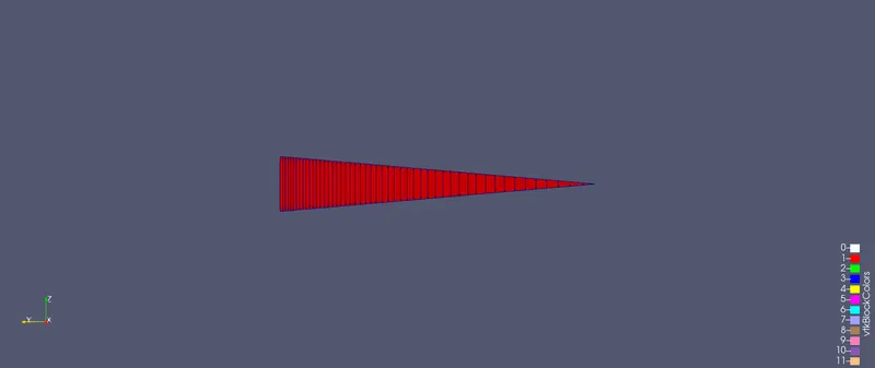
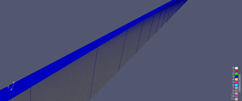
Angle `10^0` :
Angle `25^0` :
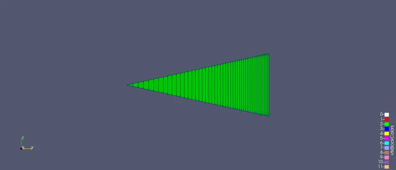
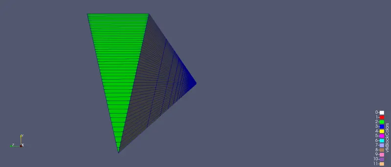
Angle `45^0` :
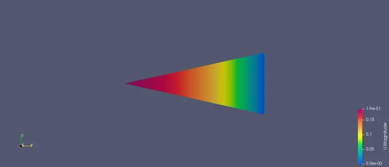
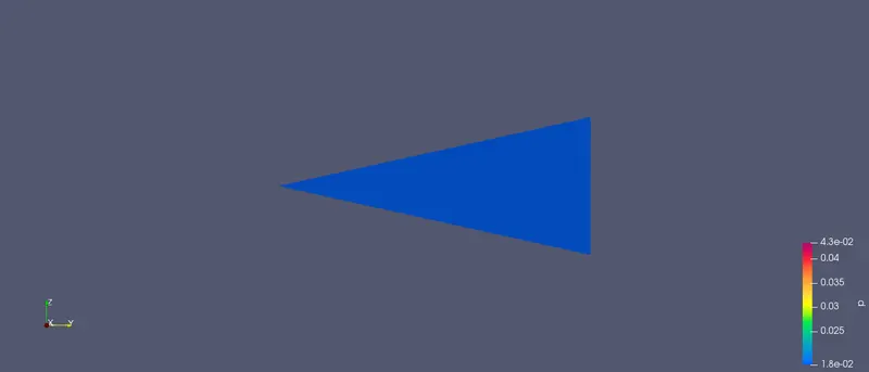
Velocity and pressure profile at various angles :
Angle `10^0` :
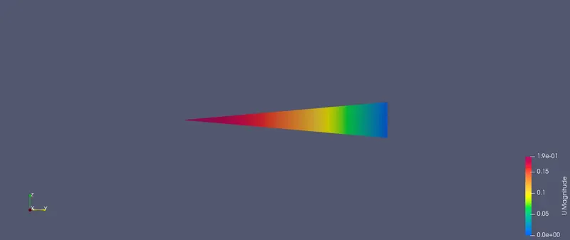
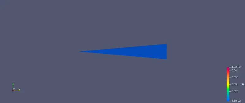
Angle `25^0` :
Angle `45^0` :
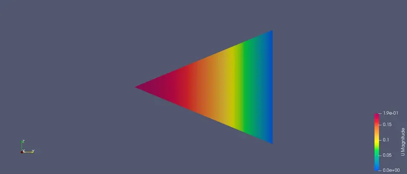
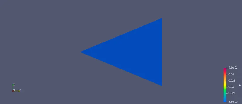
Velocity profiles :
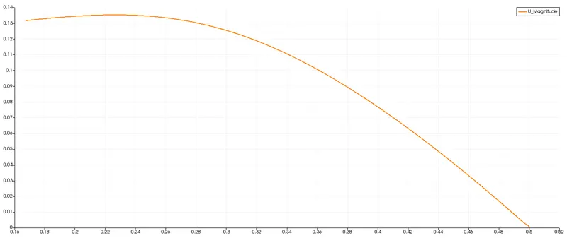
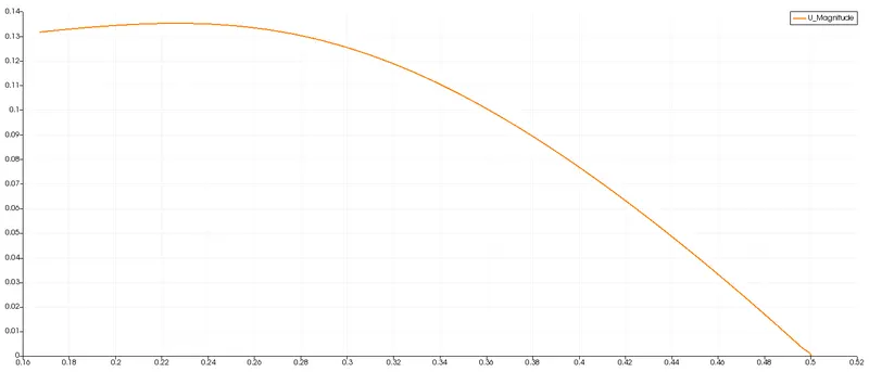
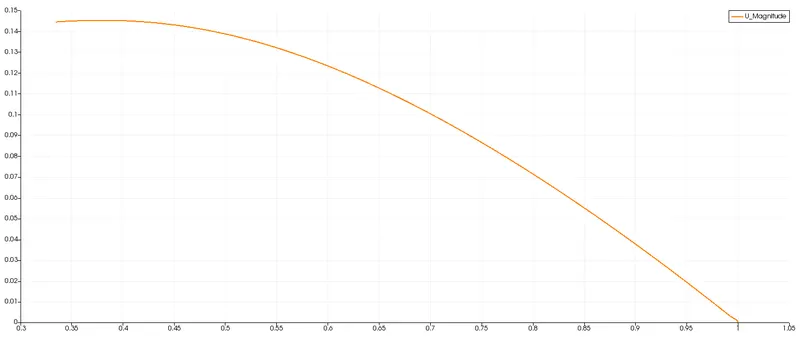
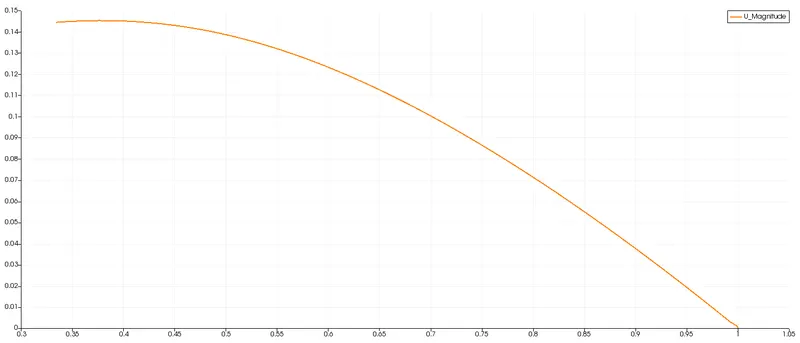
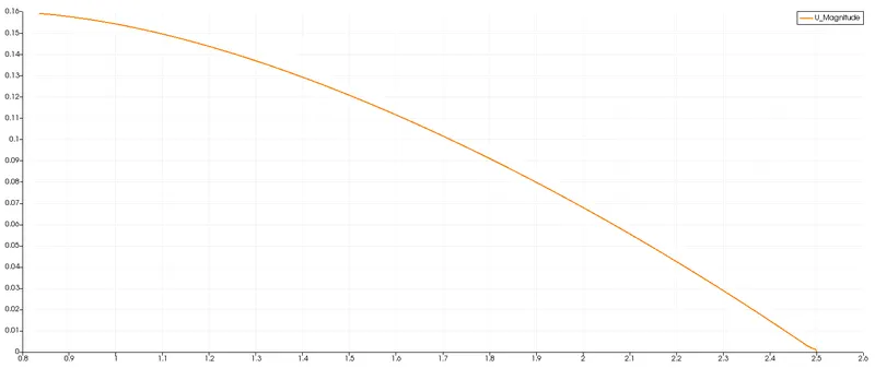
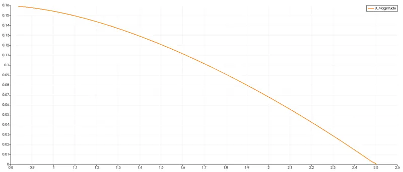
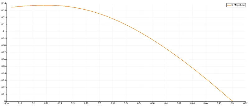
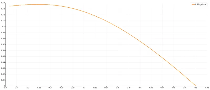
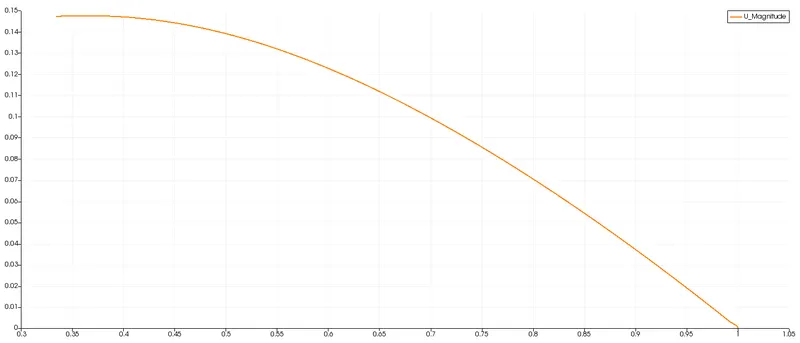
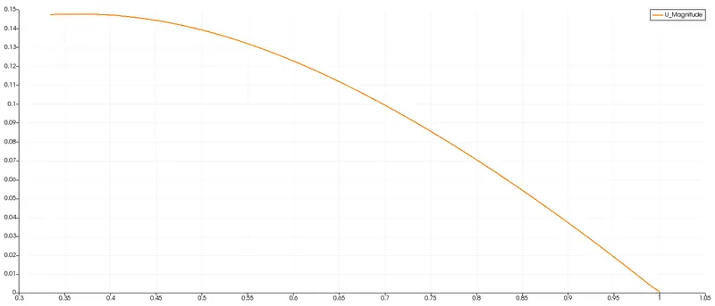
1) For wedge BC with angle of `10^0` 1) For symmetry BC with angle of `10^0`
At a distance of 0.1 :
At a distance of 0.5 :
At a distance of 1 :
At a distance of 1.5 :
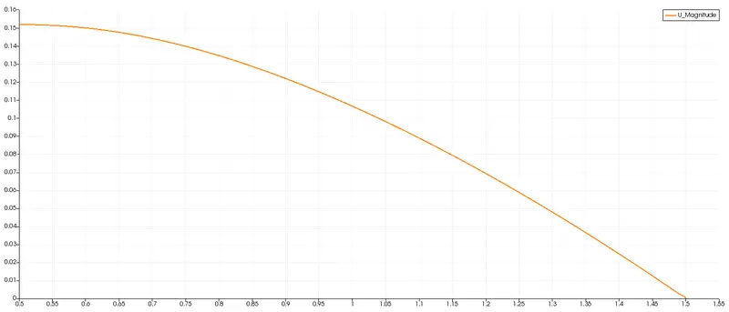
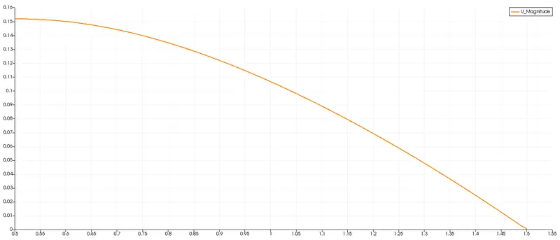
At a distance of 2.5 :
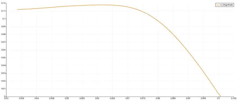
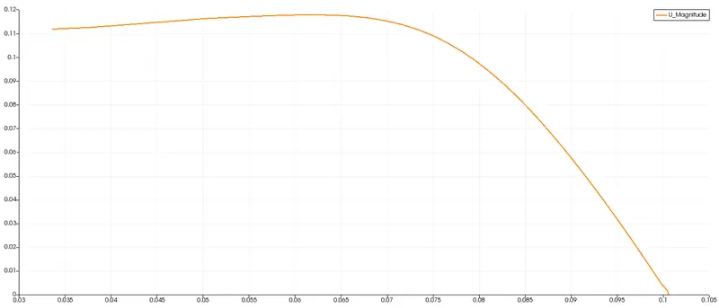
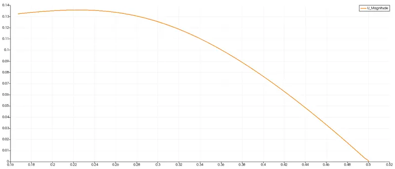
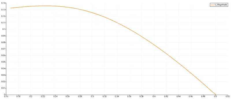
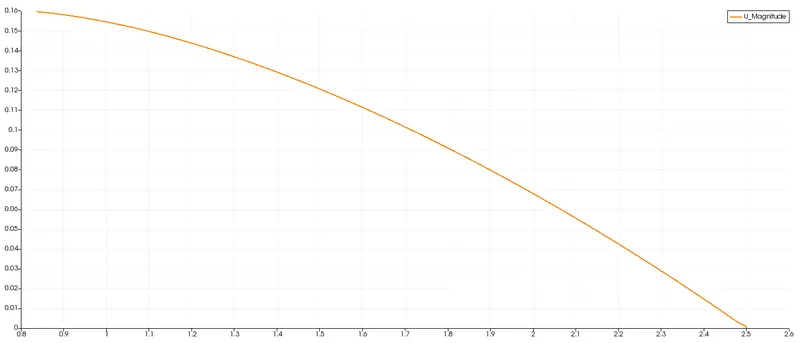
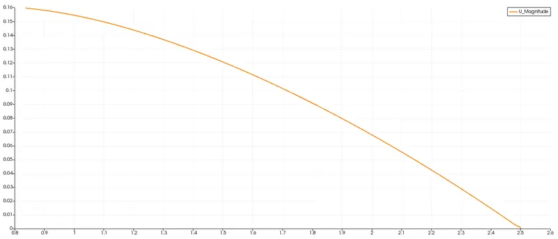
2) For wedge BC with angle of `25^0` 2) For symmetry BC with angle of `25^0`
At a distance of 0.1 :
At a distance of 0.5 :
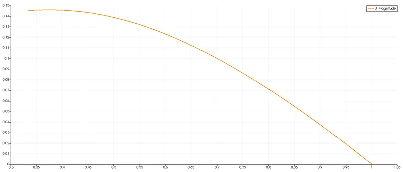
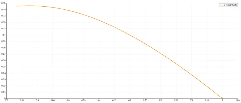
At a distance of 1 :
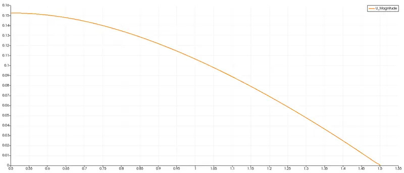
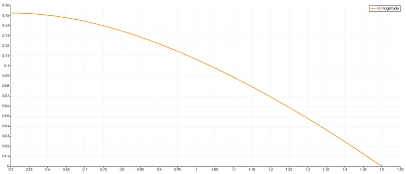
At a distance of 1.5 :
At a distance of 2.5 :
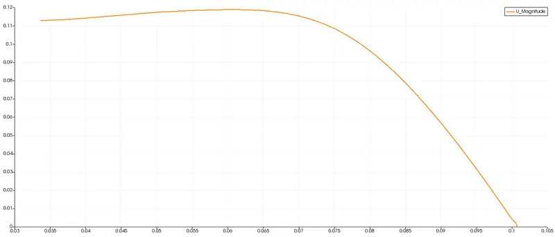
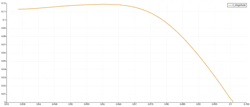
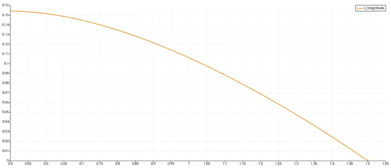
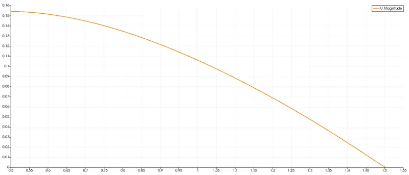
3) For wedge BC with angle of `45^0` 3) For symmetry BC with angle of `45^0`
At a distance of 0.1 :
At a distance of 0.5 :
At a distance of 1 :
At a distance of 1.5 :
At a distance of 2.5 :
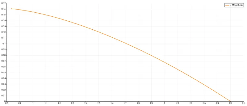
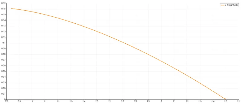
The velocity profile (graphical) is mostly similar to each other in case of wedge as well as of symmetry boundary condition with various wedge angles of `10^0`, `25^0` and `45^0`.
Pressure profile :
1) For wedge BC with angle of `10^0` 1) For symmetry BC with angle of `10^0`
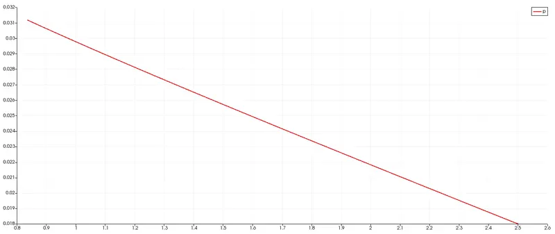
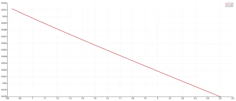
2) For wedge BC with angle of `25^0` 2) For symmetry BC with angle of `25^0`
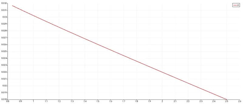
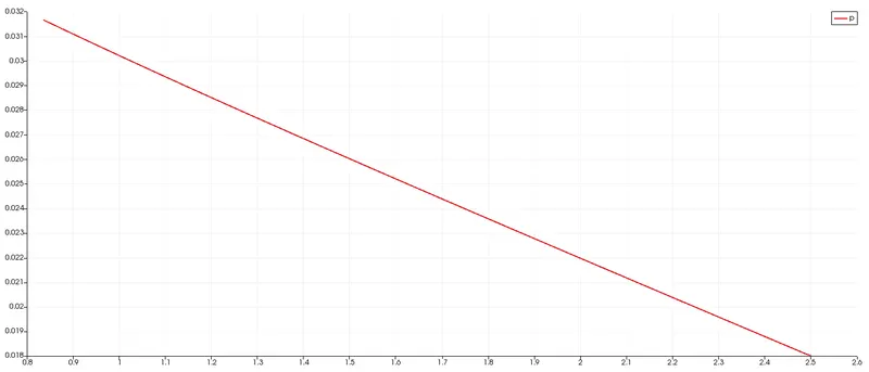
3) For wedge BC with angle of `45^0` 3) For symmetry BC with angle of `45^0`
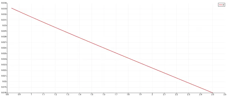
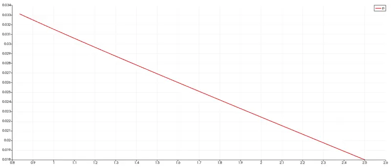
The pressure plot of both symmetry and wedge boundary condition is similar to each other for various angle of `10^0`, `25^0` and `45^0`.
Wall shear stress :
1) For wedge BC with angle of `10^0` 1) For symmetry BC with angle of `10^0`
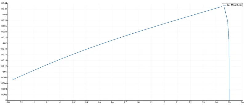
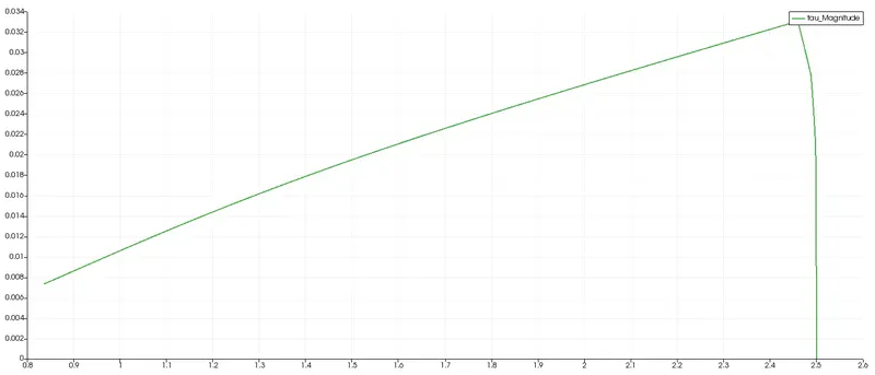
2) For wedge BC with angle of `25^0` 2) For symmetry BC with angle of `25^0`
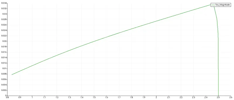
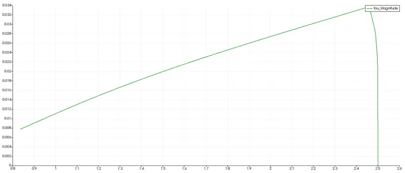
3) For wedge BC with angle of `45^0` 3) For symmetry BC with angle of `45^0`
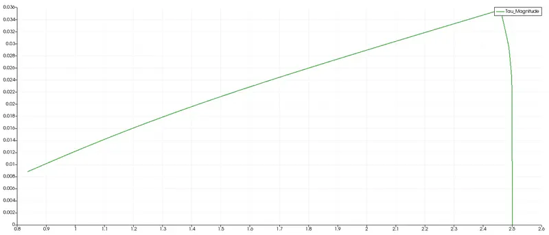
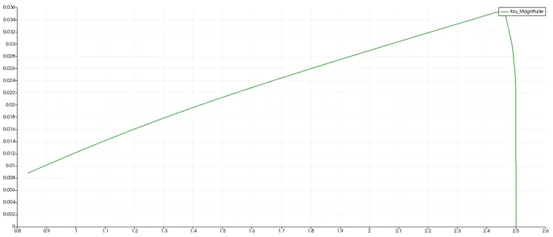
Results validation :
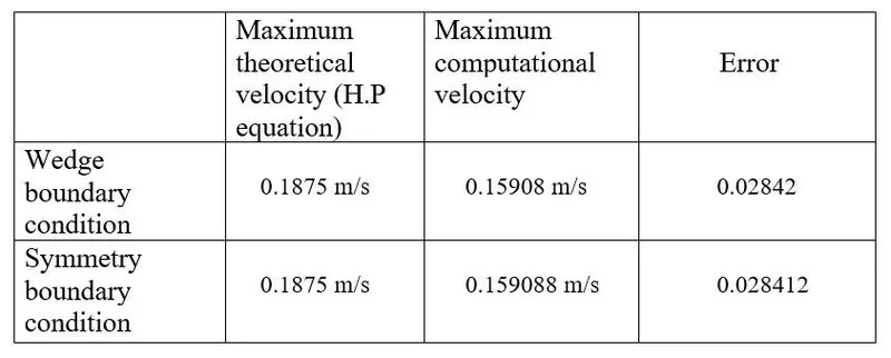
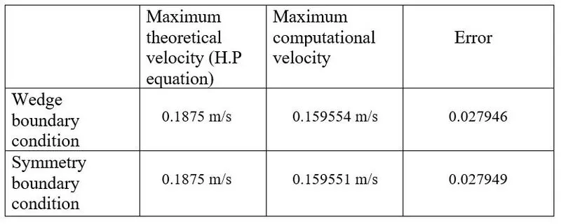
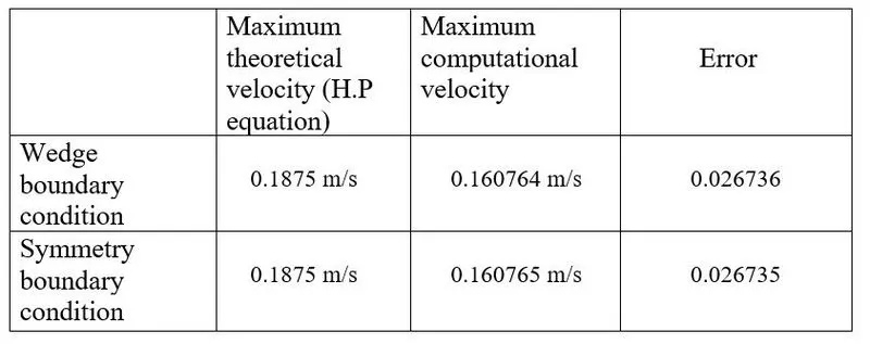
Velocity :
1) For angle of `10^0`
2) For angle of `25^0`
3) For angle of `45^0`
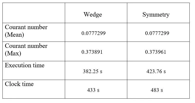
Other values :
1) For angle of `10^0`
2) For angle of `25^0`
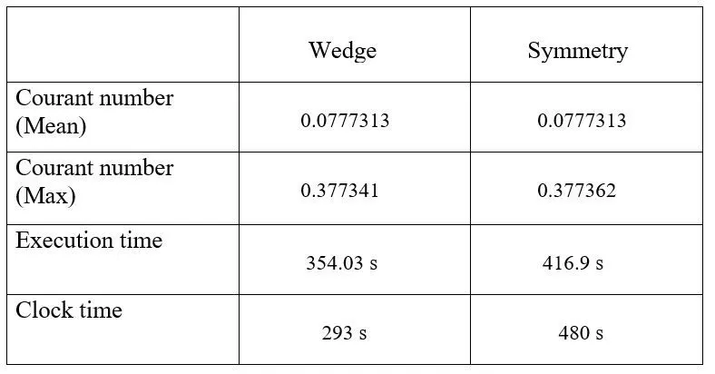
3) For angle of `45^0`
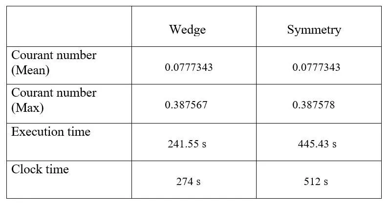
- The results shows that the values obtained from symmetry and wedge boundary conditions are not differ much.
- The maximum velocity value increases by increasing the wedge angle.
- The error between computational and theoretical value gets decreased by increasing the wedge angle.
- There is a little changes in the courant values for different conditions.
Reference :
https://en.wikipedia.org/wiki/Laminar_flow
https://en.wikipedia.org/wiki/Hagen%E2%80%93Poiseuille_equation
http://files.the-foam-house5.webnode.es/200000363-59a695aa6c/Chapter4_Pipe.pdf
https://www.simscale.com/docs/simulation-setup/boundary-conditions/symmetry/
https://www.simscale.com/docs/simulation-setup/boundary-conditions/wedge/
Keywords :
CFD, OpenFoam, MATLAB, Courant number, Hagen-Poiseuille's equation, laminar flow, wedge angle, symmetry, boundary condition, axi-symmetric flow, Reynolds number.