Simulating Fluid Sloshing effect inside a gear-box.
Aim : To simulate the fluid sloshing effect in a gearbox for different lubricants and immersion levels.
Introduction and theory :
A mechanical device that consists of moving parts is bound to experience wear due to friction and heat generation over time. A gearbox contains gears that transmit power from the engine to the wheels. Gears of different sizes are used to transmit different power outputs required, determined by gear ratios. There are different types of gear configurations that provide their own benefits, for different applications. When two gears mesh, there is metal on metal contact, resulting in face wear and heat generation due to friction. Excessive heat and face wear will reduce the life of the gear, the overall transmission efficiency, and in some cases, slip. A lubricant reduces the friction between two surfaces in contact. The selection of a lubricant for a particular gear setup is equally important, as there are operational conditions that have to be taken into consideration. Temperature, pressure, and the speed at which the gears rotate are some of the few characteristics that play a vital role in the selection of a lubricant. If a lubricant cannot withstand the temperature at which the gears operate, it will evaporate and cause damage to the gears or the gear casing. Similarly, if a lubricant is too viscous for a specific gear type, it will not perform the required task, and the gears will get damaged in this case as well. The viscosity, density and the thermal characteristics of a lubricant need to be studied before application.
Fluid sloshing is a common phenomenon that occurs inside an enclosed space subjected to internal or external movement. This phenomenon occurs when the fluid occupies a partial volume of the enclosed space. Fluid sloshing in a gearbox for different gear immersion levels and lubricant types will be observed in detail in this project.
Simulation workflow :
Solving and modelling approach:
- In order to reduce computational time, a two-dimensional simulation was performed.
- The simulation type was transient in nature, as this will allow us to investigate the behaviour of the lubricant while the gears rotate, at different points of time. The objective is to observe the behaviour of the lubricants during and after two rotations of the gears.
- Since two fluids are involved in this simulation, the Volume of Fluid model will be used, as it has the capability of calculating the volume fraction of the fluids interacting in the domain over a period of time. The solver-type used will be pressure based for this case, as the pressure field couples the two interacting phases. The momentum equations will be solved for both the phases.
- An important attribute of the VOF model is that a cell volume can only contain of the two phases that have been considered. This means that the volume fraction of a fluid phase in a cell can be either 0 or 1. To put this in context, the cell volume can contain either Engine oil/n- or air, but not both(in this case).
- The implicit protocol of obtaining the volume fraction will be used, as the stability of the solution will be higher, and less sensitive to the time step size.
- A user-defined function was created in order to control the rotation of the two gears. Creating a user-defined function allows control over the parts of the mesh that are meant to simulate the movement of the gears, and is the dynamic mesh. The dynamic mesh will be elaborated upon in the results section. An angular velocity of 200 rad/s were given to both gears, with the left gear rotating anti-clockwise and the right gear rotating clockwise. The 'DEFINE_CG_MOTION' function has been used to simulate this motion.
- The flow is expected to be turbulent in nature, and for this reason, a Realizable K-epsilon model with enhanced wall-treatment will be used. The K-epsilon model is most effective in simulating turbulent flows that are not near-wall. Since near-wall behaviour is not high in priority, scalable wall-functions will be used, making sure the flow near the wall is computed in the log-law region. A Realizable K-epsion model introduces a superior term to compute turbulent viscosity, rotational flows and flow separation. This makes it more sensitive during computation. However, the model provides highly accurate results.
I) Geometry creation:
- The geometry was imported into SpaceClaim.
- The edges of the openings of the gearbox were selected, and a fluid domain was created by using the 'Volume Extract' command. The fluid body was created, and the solid body was suppressed.
- A plane was created in the XY-plane using the 'Plane' command(Design > Plane). This plane was then used to split the body in half by using the 'Split Body' command(Design > Split Body), and the front half of the body was removed.
- The front face of the newly divided body was selected and was copied. The surface that was copied was then pasted onto a new sketch plane created in the XY-plane in a new file. This file was saved, and was the one used in this simulation.
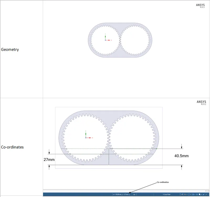
- In order to create a fluid domain for the lubricant, the co-ordinates of the fluid in contact with the boundaries were required. In order to achieve this, construction lines were created at the immersion levels required. This will be shown in the images below.
- The co-ordinates of the points enclosing the lubricant were noted by selecting the point in contact with the boundary of the gearbox geometry and noting the co-ordinates shown at the bottom of the screen.
II) Mesh details:
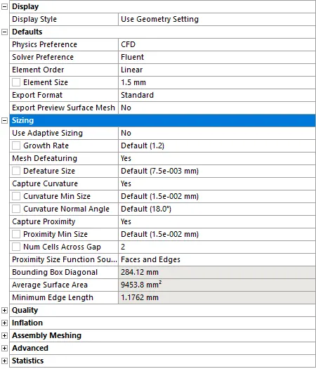
- After the geometry was imported into the Meshing module, the body was selected, and a mesh method was set as 'All triangles'.
- Two global settings were changed. The element size was changed to 1.5 mm, and the 'Capture Proximity' option was switched on.
- Under the 'Capture Proximity' settings, the number of cells along the gap was set to 2. This was done in order to provide an adequate number of cells to the gaps between the two gears.
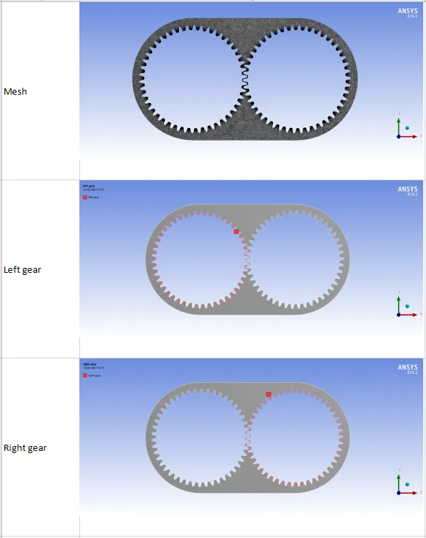
- Appropriate named selections were provided for the left gear and the right gear, the outlet.
III) Fluent settings:
(a) General settings:
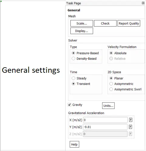
- The simulations that are going to be carried out are steady state in nature. This is set in the General section(Setup > General). Acceleration due to gravity is switched on as well, and a value of -9.81 `m/s^2` is given, with the negative sign indicating the downward direction.
Solver used: Pressure-based solver
A pressure-based solver is used for this case, as the compressibility effects are to be neglected. A density-based solver is highly accurate, but requires more computation time, and would not prove advantageous in this case. A pressure-based solver requires less computational time, and will provide accurate simulation results for this case. The pressure-based solver solves the governing equations in a sequence, unlike the density based solver.
(b) Materials :
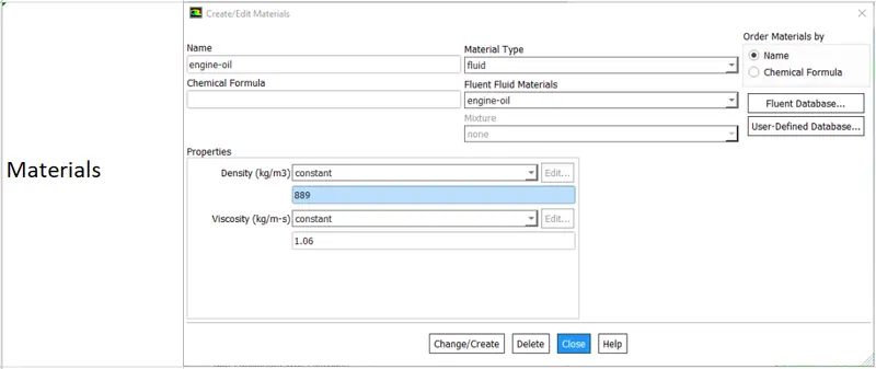
- The fluid chosen for the primary phase was air.
- The fluid chosen for the secondary phase is engine oil/n-heptane, and has been imported from the Fluent library by entering Setup > Materials > Fluid > Fluent Database.
(c) Models settings:
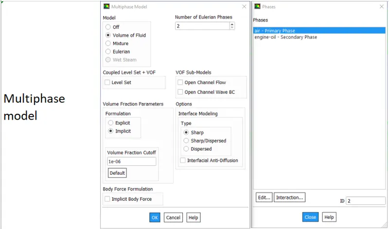
Multiphase : Volume of Fluid
- The Multiphase model is set to 'Volume of Fluid', and the Volume Fraction Parameters is set to 'Implicit'. The VOF model will compute the volume fraction of the phases in a particular cell, and will solve the momentum equation for the fluids in a cell. The pressure field couples the two phases.
- The implicit method has been chosen for higher stability.
- The two phases were specified with air as the primary phase and engine oil/n-heptane as the secondary phase.
Model : Realizable k-epsilon, with Enhanced wall-functions:
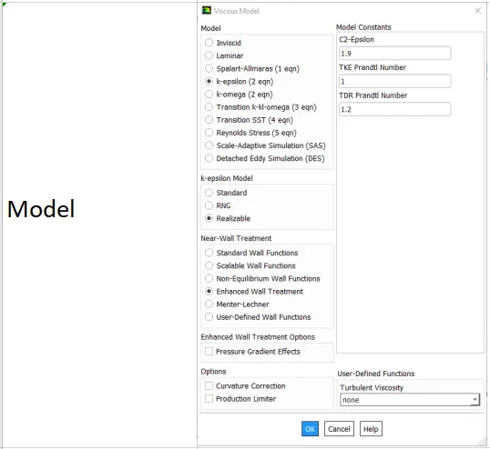
- The model that will be used in this simulation is the Realizable k-epsilon model. The reason behind the selection of this model has been mentioned in the Modelling and solving approach section. The Realizable k-epsilon model introduces a superior formulation for computing the turbulent viscosity.
- This has been done by entering Setup > Models > Viscous> k-epsilon > k-epsilon model > Realizable > Near-wall treatment >Enhanced wall Treatment.
(d) Mark and Adapt cells:`
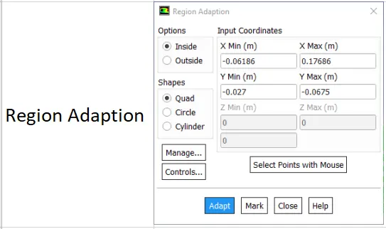
- The co-ordinates of the lubricant boundaries(obtained during geometry creation) were entered in this section, and the 'Mark' option was used to create the lubricant phase(Setting-up domain > Adapt > Mark/Adapt cells > Region).
(e) Dynamic mesh settings:
The following user-defined function was used to simulate the rotation of the two gears.
#include "udf.h"

DEFINE_CG_MOTION(right_motion, dt, vel, omega, time, dtime)
{
	vel[0] = 0.0;
	vel[1] = 0.0;
	vel[2] = 0.0;

	omega[0] = 0.0;
	omega[1] = 0.0;
	omega[2] = 2.0e2; /* [rad/s]*/
}
DEFINE_CG_MOTION(left_motion, dt, vel, omega, time, dtime)
{
	vel[0] = 0.0;
	vel[1] = 0.0;
	vel[2] = 0.0;

	omega[0] = 0.0;
	omega[1] = 0.0;
	omega[2] = -2.0e2; /* [rad/s]*/
}
- The angular velocity values were provided in the udf for both of the gears, in their respective directions.
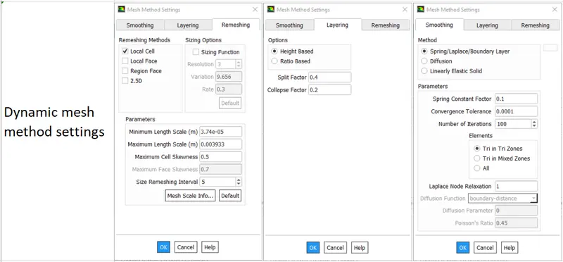
- The Dynamic mesh option was switched on, and the Smoothing, Layering and Remeshing options were switched on as well.
- The default settings were maintained for Smoothing and Layering.
- The Remeshing method was set to 'Local Cell'. The Minimum length scale, Maximum length scale, and the cell skewness values were set by using the 'Default' command in this section. This will set these values according to the mesh that has been imported. The cell skewness value has been set to 0.5, for a high level of accuracy.
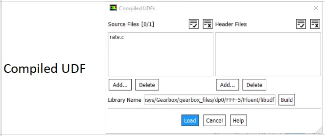
- The user-defined function was imported by entering User-defined > Functions > Compiled. The source file was then imported, built and loaded.
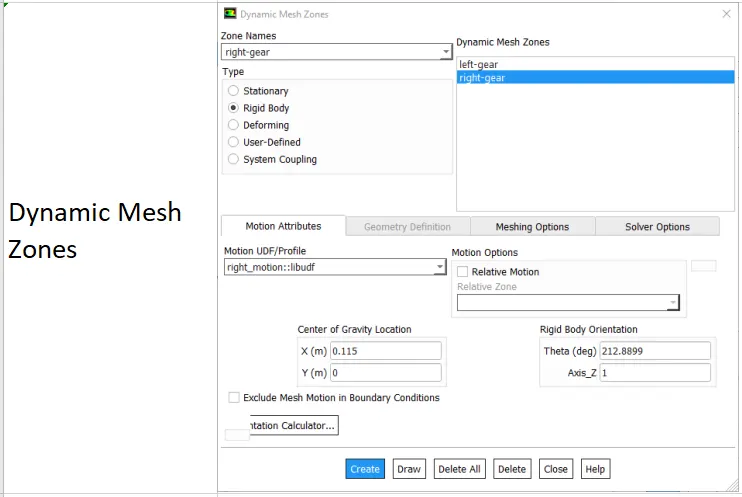
- Once this was done, the Dynamic Mesh Zones were created by selecting the zone name for the left and right gears, and providing them with their respective motions by entering Motion UDF/Profile.
(f) Method,Initialization settings, and Run calculation settings:
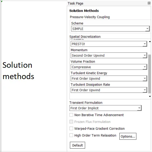
- The first-order implicit transient time stepping formulation has been used, as second order schemes are not compatible with the VOF model. This has been done by entering Solution > Methods.
- The solution is initialized by using Standard initialization. This has been done by entering Solution > Initialization.
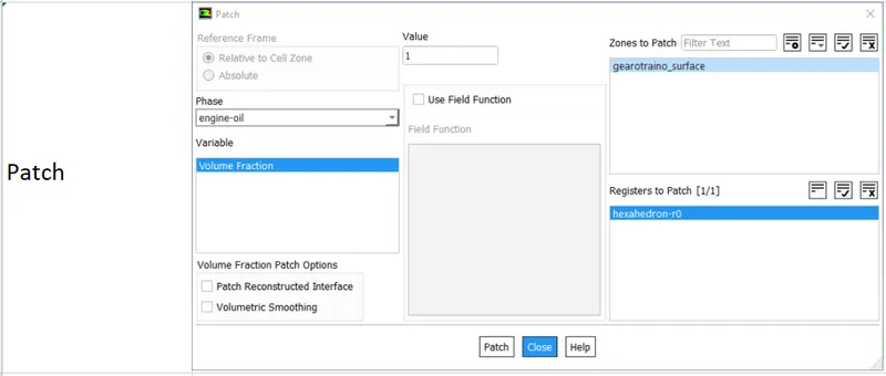
- The phases were set by entering Patch, and entering the volume fraction '1' for the lubricant, and '0' for air. As mentioned above, the volume fraction in a cell can only be 0 or 1.
- The number of time steps was set to 1600 s, and the time step size was set to 5e-05 s.
Results:
Part I:
I) Dynamic meshing:
A dynamic mesh changes the placement of the cells within it to replicate the movement of an object. In this case, the gear teeth change their angular positions with respect to time. A static mesh would not be able to capture this behavior, as the fluid within the domain interacts with the the gears. A dynamic mesh employs a variety of methods to change the position of the cells with respect to the behaviour of the moving part and the fluid surrounding it. Some of the methods will be discussed in brief in the following section.
The Spring smoothing method involves deforming the mesh in a spring-like manner. An element will deform according to the forces applied on it, using the value of displacement of the previous element. The Height Layering method will add or remove cells near the moving boundary of the component, based on a specified cut-off height. If a cell exceeds this height, cells will be added near the moving boundary. The Local cell remeshing method. A minimum cell size, maximum cell size and a skewness criterion is provided as a benchmark. If the cell or cells in a particular volume/area exceed or do not meet these criteria, the cells are grouped and replaced with smaller cells.
The applications of dynamic meshing are diverse. For example, it can be in the simulation of internal combustion, where the piston moves due to the forces generated due to the expanding gases, a centrifugal pump with rotating impellers, and turbine simulations.
II) Fluid Sloshing:
Fluid sloshing is a common phenomenon that is seen inside an enclosed space subjected to internal or external movement, and occurs when the fluid occupies a partial volume of the enclosed space. This phenomenon is seen often in the transportation of fluids, such as an oil tanker. When a fluid in an enclosed volume is disturbed due to the movement of the enclosed volume, or the movement of a device inside it, the fluid behaves erratically. In some cases the fluid gains momentum, and can potentially damage the enclosed volume due to repeated impact with the walls. This can be excessively dangerous in cases where a large volume of fluid in a container gains momentum and destabilizes the container itself. For example, a hard braking maneuver in an oil-tanker can cause fluid sloshing, and destabilize the vehicle due to the inertial force of the oil inside. In this case, the effect of sloshing can be detrimental to the health or life of a mechanical device.
However, in some cases, the erratic nature of fluid sloshing can provide some benefits. A popular method of lubrication in gearboxes, the oil splash method, uses this phenomenon to its advantage. The constant collision of the fluid caused by the movement of the gears spreads the lubricant over the gears effectively. This will be seen observed in the next section.
III) User-Defined Function:
A user-defined function is a C-program that can be created by the user for more control over certain components, or particular sections of the mesh. A user-defined function allows us to set the movement of a mesh, boundary conditions, insert formulae for variables that are not available in Fluent, and materials. Some in-built functions(macros) allow control over certain models in Fluent(VOF model being one of them as well). In this case, the user-defined function is used to control the rotation of the gears. A compiled UDF once built and loaded, can be used by the required model or models in Fluent.
IV) Mesh errors:
The 'Negative cell volume detected' occurs when the time step size is too large. The dynamic mesh creation is sensitive to time step, as the mesh will deform to capture the behviour of the fluid at a particular point of time. If the fluid in a cell moves a large distance for the step time specified, the mesh quality will degrade. The volume of the mesh becomes negative, due to a large amount of compression.
The 'dynamic mesh failed' error is caused due to excessive stretching of the cell after one time step, resulting in a high skewness value. Both of the errors mentioned above can be remedied by simply decreasing the time step size, so that the mesh deformation is within a tolerable range. The max skewness value should be reduced, in order to locally remesh the cells that do not meet this criterion, resulting in a finer mesh in that specific region. For this reason, providing a reasonable maximum and minimum dynamic cell size is important.
Part II:
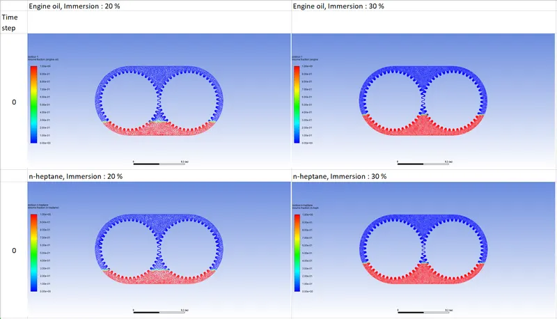
The following images contain the contours for Volume fraction of the lubricant, for different immersion levels and lubricant types.
Initial volume fraction:
Volume fraction at different time steps:
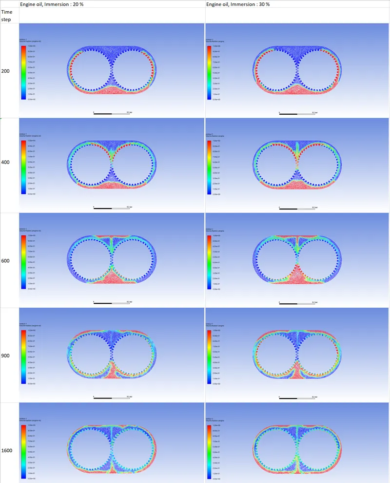
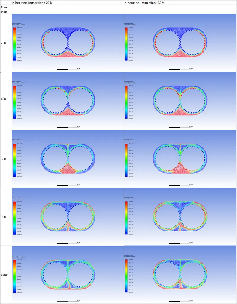
From the contours above, the effect on the gear movement on the lubricant can be observed. The submerged gears carry some volume of the viscous lubricant as it rotates, and the majority of the teeth are well lubricated at this point, as shown at time step 200. At time step 400, the lubricated gear teeth meet, and the excess lubricant/ lubricant that is unable to fit through the gap between the contacting teeth, is ejected upward. This is where the fluid sloshing begins. This ejected lubricant meets the top wall and spreads outward. After the lubricant impinges on the wall, it spreads on the top wall, and proceeds downward, to the base of the gearbox. Some of the lubricant lubricates the contacting gear teeth. The fluid sloshing caused due to the movement of the gears in this case is favourable, as the lubricant proceeds to the base and lubricates the teeth once more.
Comparing the volume fraction plots, it can be said with certainty that the gears lubricated by engine oil at an immersion level of 20% percent performs the worst, as it does not effectively lubricate the gear teeth. At time step 600, it can be seen that gear teeth at the bottom are barely lubricated by the engine oil, as the volume of engine oil present in the vicinity is insufficient. This suggests that the viscosity of the engine oil at this immersion level will not effectively lubricate the gear teeth. This point is further accentuated by the lack of lubrication in the gap between the gear teeth in contact, at time step 1600.
Engine oil at an immersion level of 30 % performs much better at every single time step. At time step 600, it can be seen that the engine oil is still in contact with the gear teeth at the bottom, and an improvement over the previous case. The higher level of immersion seems to have benefited the lubrication. The fluid ejected from the teeth in contact has increased as well, and it can be assumed that the speed at which the fluid volume will reach the base again has increased. The lubricant has spread over the gears more evenly, and this is seen at time step 900. If time step 1600 is observed, it is seen that there is a significant amount of lubricant in the gap between the gear teeth in contact. The volume of lubricant between the flank and the bottom land has significantly increased as well. However, n-heptane at an immersion level of 20% performs better than both of these cases.
If the contours for n-heptane at an immersion level of 20% are observed, it is clear that n-heptane outperforms engine oil at an immersion level of 20%, in terms of lubrication. In fact, it becomes comparable to the engine oil at an immersion level of 30%. The reason that this behaviour is observed, is due to the fact that n-heptane is far less viscous compared to engine oil. The fluid that has been ejected upward, as seen at time step 600, will most certainly possess higher velocity compared to engine oil. This is where lubrication due to fluid sloshing will benefit the most. The ejected fluid will splatter more, and will reach the base of the gearbox at a much faster rate, since the viscosity of n-heptane is much lower. This can be seen at time step 900. The engine oil has only covered one-third of the circumference of the boundary, while n-heptane has crossed half of the total circumference of the boundary. Since the speed of the fluid coming to the base is greater, it is logical that the fluid sloshing that occurs at the base due to the collision of the n-heptane streams coming from opposing ends will be greater than that of engine oil. This will cause the lubricant to splash onto the gears at the base, enhancing lubrication even further. The best lubrication is obtained from n-heptane at an immersion level of 30%. All of the benefits mentioned above are enhanced with an increase in the volume of n-heptane. The average volume of fluid available at the base of the gearbox is the highest in this case.
Hence, it can be said that n-heptane is a better lubricant in this particular case(if thermal factors are not considered).
Conclusions:
From the results above, it can be said that the immersion level of a fluid has an impact on the fluid sloshing in the enclosed volume. Fluid sloshing increases with the increase in the immersion level. Lubrication of the gears benefits from a higher immersion level. Lubrication and fluid sloshing is heavily dependent on the viscosity and the density of a fluid, and is an important design factor to take into consideration. The speed at which the gears rotate must be taken into consideration, as a highly viscous fluid will not be able to lubricate the gears efficiently, and the time taken to lubricate the gears is high. In this particular case, the engine oil is unable to lubricate the gears efficiently at an immersion level of 20%, but improves at an immersion level of 30%. However, despite the higher immersion level, n-heptane with lower immersion outperforms both cases using engine oil. The lower viscosity and density enhances fluid sloshing, due to which the fluid lubricates the gear much more effectively. Hence, it can be said that the speed of the gears and the geometry of the gearbox plays an important role in the selection of a lubricant, and a gear rotating at a high angular velocity will benefit from a lubricant with lower viscosity.