Similink model to sense the temperature of a heater and control a actuator(Fan)
Aim:- Use a thermistor to sense the temperature of a heater & turn on or turn off the fan as per below conditions:-
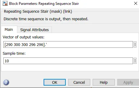
- Temperature source: 20 °C from 0 to 10 seconds, 27 °C from 10 to 30 seconds, 23 °C from 30 to 50 seconds
- Fan conditions: ON if the temperature above 25 °C, OFF otherwise
Objectives:-
- Generate a wave of temperature coeficient using suitable block
- Obtain the characterictics curve for chnage in voltage w.r.t time
- Control a DC motor for a gevn condition
Blocks used:-
- Repeating Sequence Stair:- The Repeating Sequence Stair block outputs and repeats a stair sequence that you specify with the Vector of output values parameter.
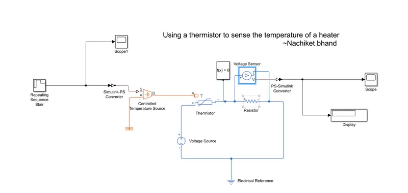
- Simulink-PS Convertor:- Converts the Simulink input signal to a Physical Signal.
- Thermall & electrical reference :- these provides the reference point to the respective signals
- Scope :- to view te characterictics of a property with respect to the time(Simulation Time)
- Thermistor:- is a resistance thermometer, or a resistor whose resistance is dependent on temperature.
- Volatge Source :- this block provides a voltage source to the systen
- Resistor:- The voltage-current (V-I) relationship for a linear resistor is V=I*R, where R is the constant resistance in ohms.
- Voltage Sensor :- The block represents an ideal voltage sensor, that is, a device that converts voltage measured between any electrical connections into a physical signal proportional to the voltage
- Switch :- Pass through input 1 when input 2 satisfies the selected criterion; otherwise, pass through input 3.
-
Ideal Rotational motion Sensor :- The block represents an ideal mechanical rotational motion sensor, that is, a device that converts an across variable measured between two mechanical rotational nodes
- voltage COntrolled Source :- The block represents an ideal voltage source that is powerful enough to maintain the specified voltage at its output regardless of the current passing through it
Case 1)
Generating the required signal :-
Simulink Model :-
Output :-
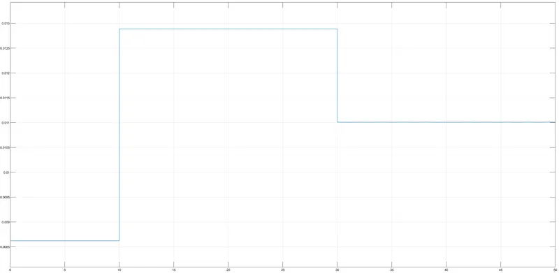
This curve shows the change in voltage wrt time, as the condition given below is satisfied ;-
"20 °C from 0 to 10 seconds, 27 °C from 10 to 30 seconds, 23 °C from 30 to 50 seconds"
case 2)
Simulink Model :-
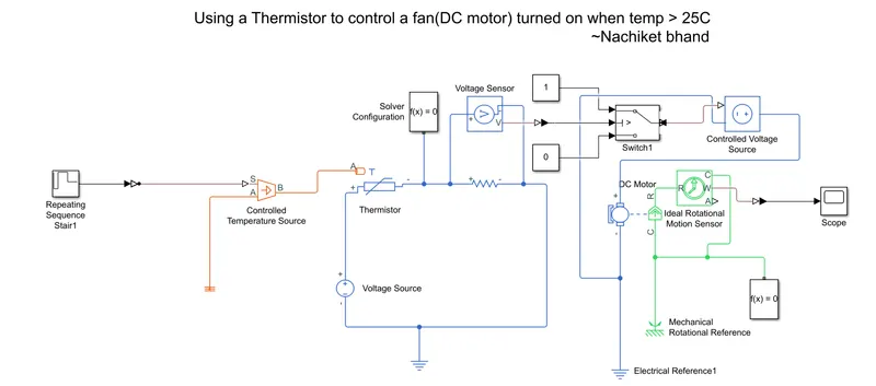
Output :-
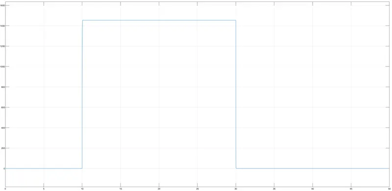
Hence the plot clearly shows the fan is on when the temperature is above 25 C (10 sec - 30 sec) and it is off otherwise.
Conclusion :-
- Hence with the given conditions is satisfied using repeating sequence stair and switch blocks.
- Working of the model and its underlying principal.