Section Modulus calculation and optimization
SECTION MODULUS CALUCULATION AND OPTIMIZATION
SECTION MODULUS:
It is a way of quantifying a cross-section of a given geometry. It is directly proportional to the area moment of inertia of the cross-section. Higher the section modulus, the more the moment of inertia, more stiffness and thus more resistance to deformation and bending. Section modulus can be improved by varying the geometry of the cross-section. In other words, stiffness can be improved by just improving the geometry without the need for adding extra material.
Section Modulus(S) Calculation:
S= I / Y
Here,
S = Section modulus
I= Moment of Inertia (Unit mm 4)
Y= Distance from Neutral axis to the extreme end (unit mm)
The Unit of a “section modulus” is (mm3)
Elastic section modulus
For general design, the elastic section modulus is used, applying up to the yield point for most metals and other common materials.
The elastic section modulus is defined as S = I / y, where I is the second moment of area (or area moment of inertia, not to be confused with moment of inertia) and y is the distance from the neutral axis to any given fibre. It is often reported using y = c, where c is the distance from the neutral axis to the most extreme fibre, as seen in the table below. It is also often used to determine the yield moment (My) such that My = S × σy, where σy is the yield strength of the material.
| Cross-sectional shape | Figure | Equation | Comment |
|---|---|---|---|
| Rectangle |  |
Solid arrow represents neutral axis | |
| doubly symmetric I-section (major axis) | 
|
NA indicates neutral axis | |
| doubly symmetric I-section (minor axis) |  |
NA indicates neutral axis | |
| Circle |  |
Solid arrow represents neutral axis | |
| Circular hollow section |  |
Solid arrow represents neutral axis | |
| Rectangular hollow section |  |
NA indicates neutral axis | |
| Diamond |  |
NA indicates neutral axis | |
| C-channel | |
NA indicates neutral axis |
 ,
,
SECTION MODULUS CALCULATION IN HOOD
Case -1
For case 1 the below section were considered parallel to x-coordinate for calculating the section modulus.
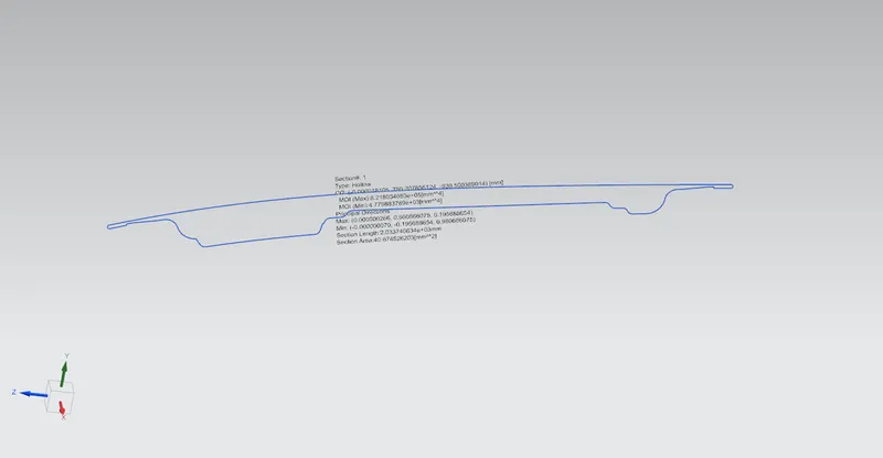
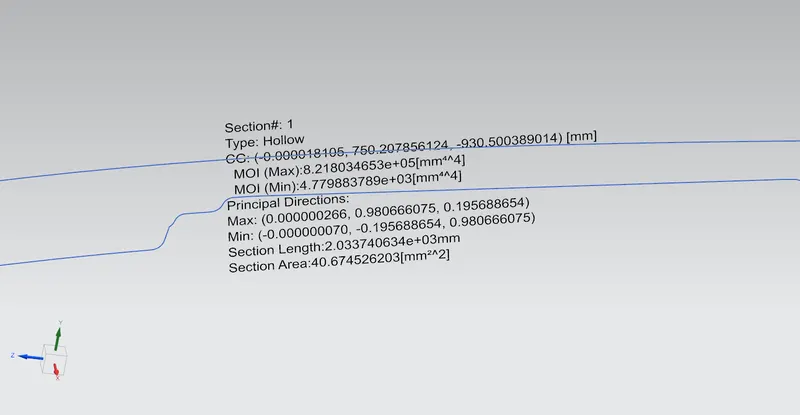
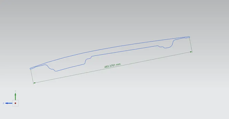
Moment of Inertia (MAX) = 8.218034653 x 10^5 [mm^4]
Moment of Inertia (MIN) = 4.779883789 x 10^3 [mm^4]
Section Modulus, S = Moment of Inertia (MOI) / Distance between the neutral axis and the extreme end of the object (y)
Y=483.3761/2=241.68805 mm
S=I/Y
For MOI max,
S = (8.218034653 x 10^5 [mm^4])÷(241.68805 mm)
S = 3400.2651 mm^3
For MOI min,
S = (4.779883789 x 10^3 [mm^4])÷(241.68805mm)
S = 19.7770795 mm^3
Case -2
For case 2 the below section were considered parallel to x-coordinate for calculating the section modulus.
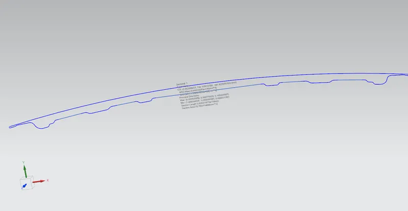
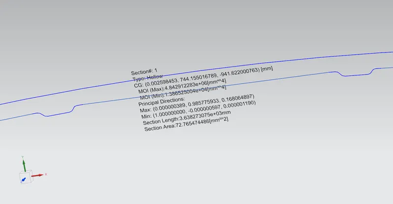
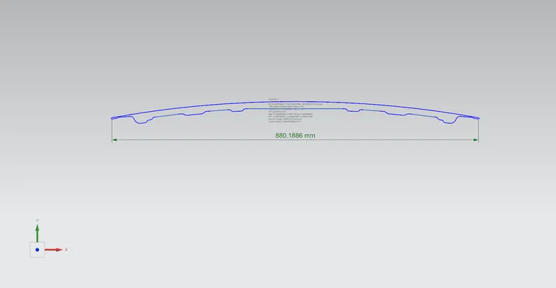
Moment of Inertia (MAX) = 4.842912283 x 10^6 [mm^4]
Moment of Inertia (MIN) = 1.386525004 x 10^4 [mm^4]
Section Modulus, S = Moment of Inertia (MOI) / Distance between the neutral axis and the extreme end of the object (y)
Y=880.1886/2=440.0943 mm
S=I/Y
For MOI max,
S = (4.842912283 x 10^6 [mm^4])÷(440.0943 mm)
S = 11,004.2604 mm^3
For MOI min,
S = (1.386525004 x 10^4 [mm^4])÷(440.0943 mm)
S = 31.50517 mm^3
Conclusion
So, here the difference can be seen in the moment of inertia and the change in the section modulus can be seen by the change in the design(depth).