Section Modulus calculation and optimization
Aim:
To find the section modulus of the hood and optimization to improve the overall section modulus.
Objective:
Use the section from your Hood design and calculate the section modulus using the formula S= I/y.
Section Modulus:
The section modulus (S) is geometry property of the cross section used for designing beams and flexural members. It does not represent anything physically.
Definition of Section Moduls -:
It is the ratio of area moment of inertia about the neutral axis and of the destance of outermost fiber from the neutral axis..
Display this with S ..
S=I/Y [ Units-: mm^3 or m^3]
wher as
S = Section Moduls.
I = Area moment of inerla .
Y = Distance from neutral axis to the outermost fiber.
ELASTIC MODULUS:
For general design, the elastic section modulus is used, applying up to the yield point for most metals and other common materials.The elastic section modulus is defined as S = I / y, where I is the second moment of area (or area moment of inertia, not to be confused with a moment of inertia) and y is the distance from the neutral axis to any given fiber. It is often reported using y = c, where c is the distance from the neutral axis to the most extreme fiber, as seen in the table below. It is also often used to determine the yield moment (My) such that My = S ⋅ σy, where σy is the yeild strength of the material
PLASTIC SECTION MODULUS:
The plastic section modulus is used for materials where elastic yielding is acceptable and plastic behavior is assumed to be an acceptable limit. Designs generally strive to ultimately remain below the plastic limit to avoid permanent deformations, often comparing the plastic capacity against amplified forces or stresses.The plastic section modulus depends on the location of the plastic neutral axis (PNA). The PNA is defined as the axis that splits the cross-section such that the compression force from the area in compression equals the tension force from the area in tension. So, for sections with constant yielding stress, the area above and below the PNA will be equal, but for composite sections, this is not necessarily the case.The plastic section modulus is the sum of the areas of the cross-section on each side of the PNA (which may or may not be equal) multiplied by the distance from the local centroids of the two areas to the PNA:

The plastic section modulus is used to calculate the plastic moment, Mp, or full capacity of a cross-section. The two terms are related by the yield strength of the material in question, Fy, by Mp = Fy ⋅ Z. Plastic section modulus and elastic section modulus are related by a shape factor which can be denoted by k, used for an indication of capacity beyond the elastic limit of the material. This could be shown mathematically with the formula:-

Moment of inertia is defined as the quantity expressed by the body resisting angular acceleration which is the sum of the product of the mass of every particle with its square of a distance from the axis of rotation. Or in more simple terms, it can be described as a quantity that decides the amount of torque needed for a specific angular acceleration in a rotational axis. Moment of Inertia is also known as the angular mass or rotational inertia. The SI unit of moment of inertia is kg m2.
Moment of inertia is usually specified with respect to a chosen axis of rotation. It mainly depends on the distribution of mass around an axis of rotation. MOI varies depending on the axis that is chosen.
In General form,
Moment of Inertia is expressed as I = m × r2
where,
m = Sum of the product of the mass.
r = Distance from the axis of the rotation.
Area Moment of Inertia:
The area moment of inertia of a beam cross section area measures the beam ability to resist bending. The larger the moment of inertia less will be the bend.
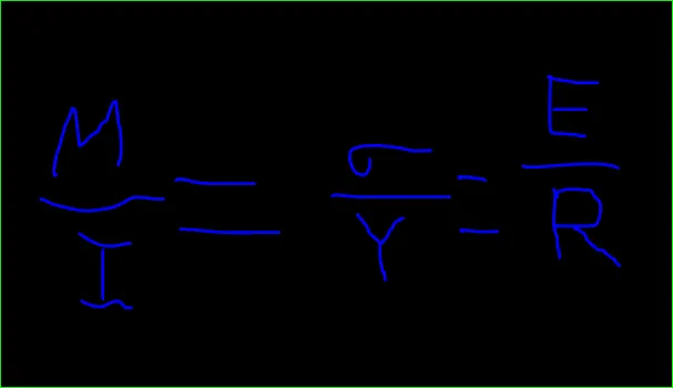
Where,
M = Bending Moment
I = Area moment of Inertia
E = Young modulus
R = Radius of gyration
Y = Distance from neutral axis to the outermost fiber.
Neutral Axis: When beam is subjected to pure bending the top most fibres of the beam are subjected to maximum compression, while the bottom most fibre of the beams are subjected to maximum tension.
- This picture contains the following scene, Diagram of a beam on its narrow edge supported at both ends. A man is walking on a straight beam. Diagram of a beam resting on its flat side supported at both ends. A man is walking on the straight beam and its bending in the middle.
Calculation:
Section Modulus :
Case 1:
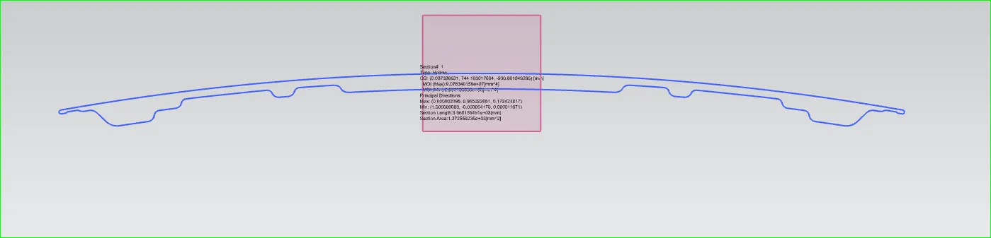
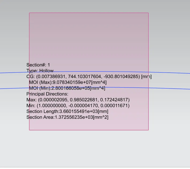
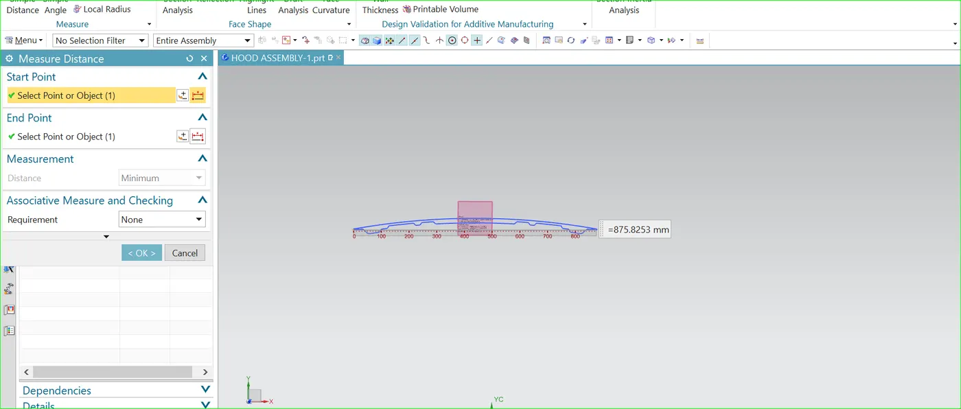
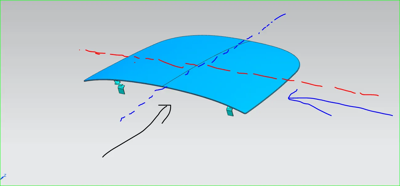
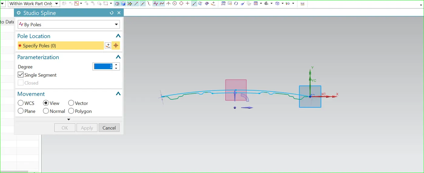
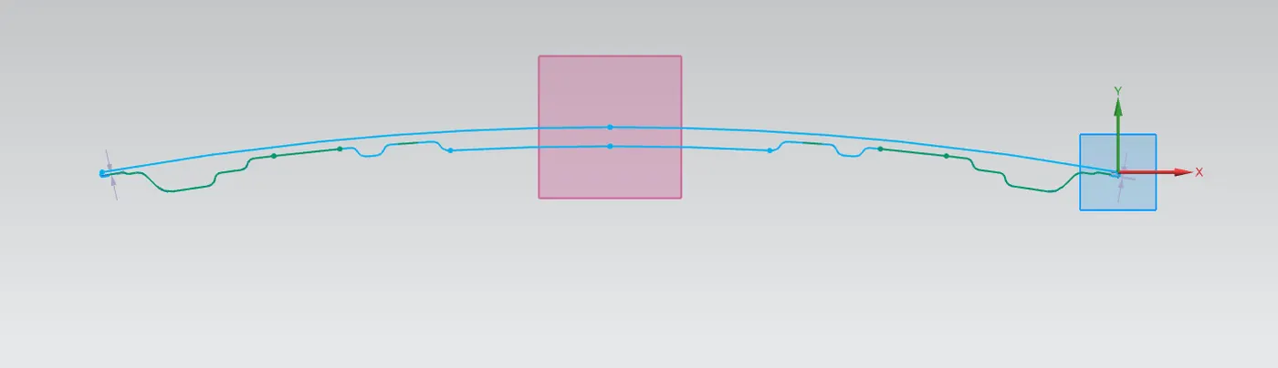
>Here we are considered the innerpannel section of the to analysis the section inertia analysis after doing the we got the desired results shown in the above image
Moment of Inertia (MOI), Imax =9.07834015x10^7 [mm^4]
Moment of Inertia (MOI), Imin = 2.800166058x10^5[mm^4]
Distance between the neutral axis and the extreme end of the object, y= 875.8253/2= 437.91265
Section Modulus, S = Moment of Inertia (MOI), I / Distance between the neutral axis and the extreme end of the
S = I/Y
For Maximum (MOI),
S =9.07834015X10^7/ 437.91265= 0.0207309383503= 2.7309383503X10^6 [mm^3]
{ Smax =2.7309383503X10^6 [mm^3] }
For Minimum (MOI),
S =2.800166058x10^5/437.91265=0.0063943484117= 6.3943484117X10^2[mm^3]
{ S min=6.3943484117X10^2[mm^3] }
Hood Optimized Design:
AFTER THE CHANGES WILL BE MADE IT CHANGES THE VALUES THEY ARE:
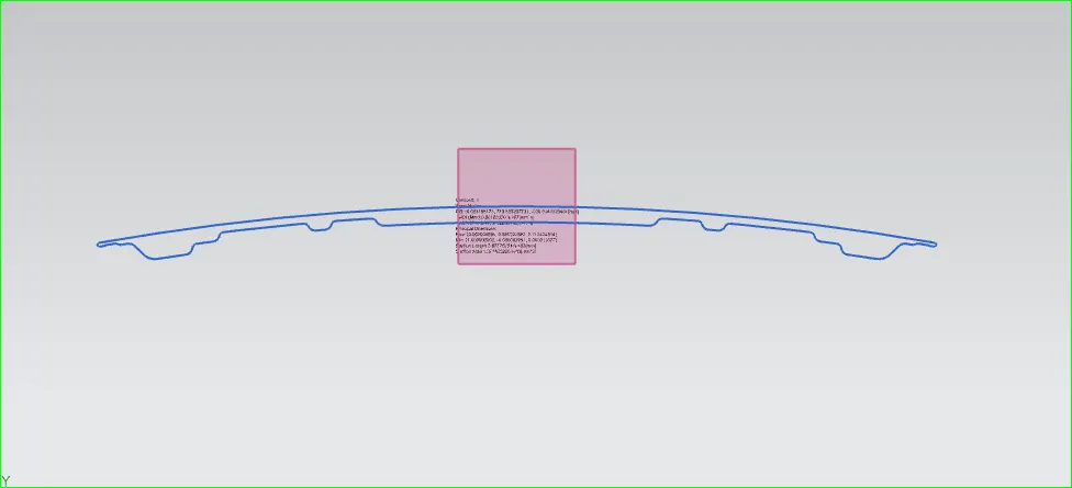
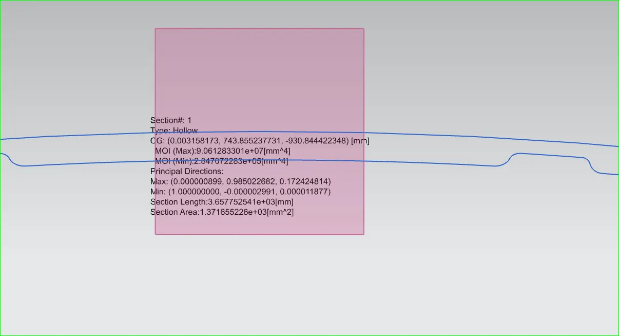
Moment of Inertia (MOI), Imax = 9.061283301X 10^7[mm^4]
Moment of Inertia (MOI), Imin = 2.847072283x10^5[mm^4]
Distance between the neutral axis and the extreme end of the object, y= 875.8253/2= 437.91265
Section Modulus, S = Moment of Inertia (MOI), I / Distance between the neutral axis and the extreme end of the
S = I/Y
For Maximum (MOI),
S = 9.061283301X10^6/437.91265=0.02069119880049= 2.0691988049X10^5[mm^3]
{ S max= 2.069188049X10^5[mm^3] }
For Minimum (MOI),
Smin =2.847072283x10^5[mm^4]/ 437.91265=0.006514616111[mm^3]= 6.5014616111x10^2[mm^3]
{ Smin= 6.5014616111x10^2[mm^3] }
CONCLUSION
- The complete assembly of the hood outer and hood inner panel was designed as per requirement.
- The latch and the hinges were also placed at appropriate position by following a latch trajectory strategy.
_________________=:THANK YOU:=__________________________