Section Modulus calculation and optimization
HOOD DESIGN - Section Modulus,
Section Modulus is defined as the ratio of area moment of inertia about the neutral axis and to the distance of outermost fiber from the neutral axis
S = I/y
Where as,
S = Section Modulus
I = Moment of Inertia
y = distance between the neutral axis and the extreme end of the object
Section modulus is a geometric property for a given cross-section used in the design of beams or flexural members. Other geometric properties used in design include for tension and shear, radius of gyration for compression, and second moment of area and polar second moment of area for stiffness. Any relationship between these properties is highly dependent on the shape in question. Equations for the section moduli of common shapes are given below. There are two types of section moduli, the elastic section modulus and the plastic section modulus. The section moduli of different profiles can also be found as numerical values for common profiles in tables listing properties of such.
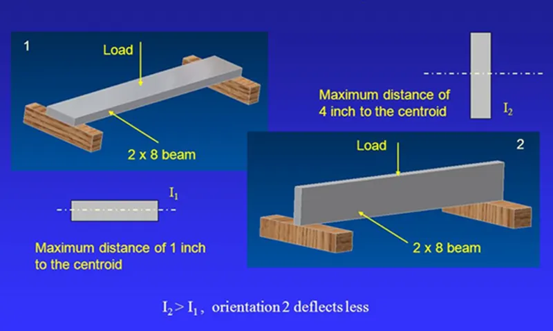
Elastic section modulus,
For general design, the elastic section modulus is used, applicable up to the yield point for most metals and other common materials.
The elastic section modulus is defined as S = I / y, where I is the second moment of area (or area moment of inertia, not to be confused with moment of inertia) and y is the distance from the neutral axis to any given fibre. It is often reported using y = c, where c is the distance from the neutral axis to the most extreme fibre, as seen in the table below. It is also often used to determine the yield moment (My) such that My = S ⋅ σy, where σy is the yiels strength of the material.
Bending moment is proportional to area moment of inertia (M = I);
The bending moment is directly proportional to the area moment of inertia. The area moment of inertia, also known as the second moment of area or moment of inertia, is a property of a cross-sectional shape that quantifies its resistance to bending. It depends on the shape and distribution of the cross-sectional area. The bending moment, on the other hand, is the internal moment that develops within a beam or structural element when subjected to an external load or moment. It causes the beam to bend or deform.
According to Euler-Bernoulli beam theory, the relationship between the bending moment (M) and the curvature (κ) of a beam is given by the equation M = E * I * κ, where E is the modulus of elasticity and I is the area moment of inertia. This equation demonstrates that the bending moment is directly proportional to the area moment of inertia.
In practical terms, a larger area moment of inertia indicates a stiffer and more resistant cross-section, which results in a higher bending moment required to produce a certain amount of curvature or deformation in the beam. Therefore, increasing the area moment of inertia can help increase the structural strength and stiffness of a beam.
M = (E * I * y) / (ρ)
Where,
M is the bending moment E is the modulus of elasticity of the material I is the area moment of inertia y is the perpendicular distance from the neutral axis to the point of interest ρ is the radius of curvature of the bending moment
This formula shows that the bending moment is directly proportional to the area moment of inertia (I).
Here i have tried upto 08 cases for the section modulus improvement study,
Case I; As per actual design of,
Panels thickness = 0.75mm ; Max inner panel offset = 25mm
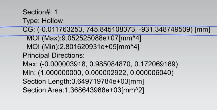
Case II;
Panels thickness = 0.70mm; Max inner panel offset = 25mm
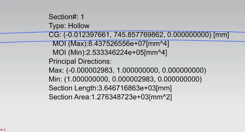
Case III;
Panels thickness = 0.80mm; Max inner panel offset = 25mm
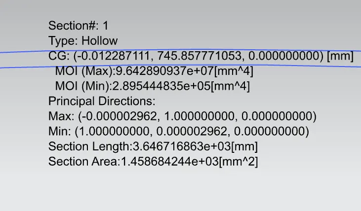
Case IV;
Panels thickness = 0.80mm; Max inner panel offset = 30mm
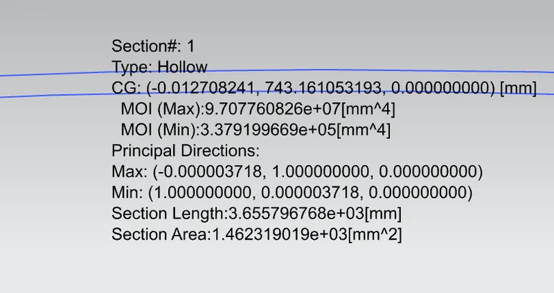
Case V;
Panels thickness = 0.75mm; Max inner panel offset = 30mm
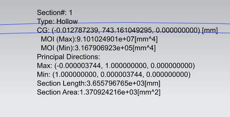
Case VI;
Panels thickness = 0.70mm; Max inner panel offset = 24mm
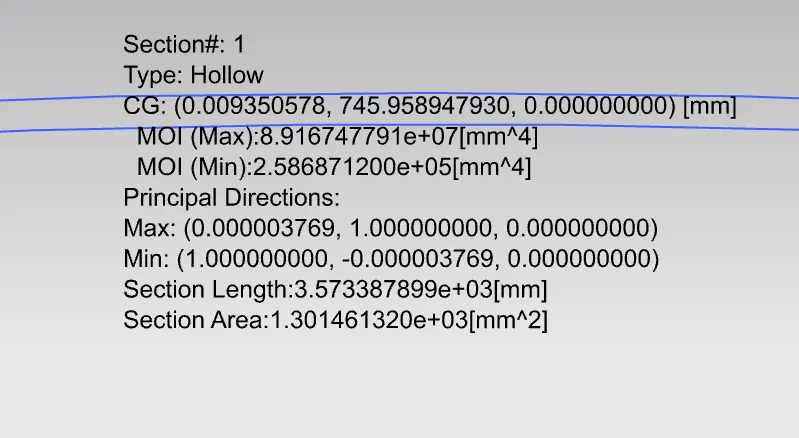
Case VII ;
Panels thickness = 0.75mm; Max inner panel offset = 24mm
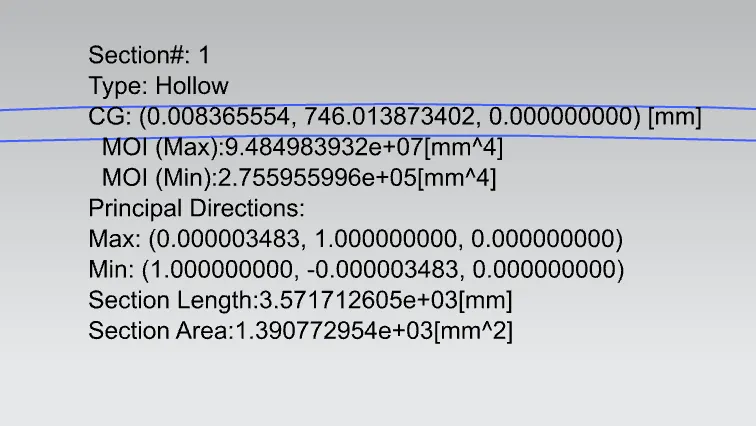
Case VIII ;
Panels thickness = 0.80mm; Max inner panel offset = 24mm
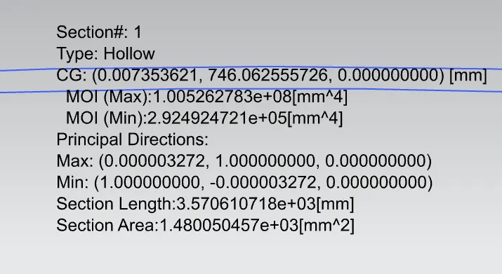
Section modulus calculation,
| Case no. | Upper & inner panel thickness (mm) | Inner panel max offset from upper panel (mm) | MIN (MOI ) from NX (I value) (mm^4) | Section modulus S = I / Y (mm^3) | |
| 2 |
|
25 | 2.53 x 10^5 | 572.5 | |
| 6 |
|
24 | 2.59 x 10^5 | 586.1 | |
| 7 | 0.75 | 24 | 2.76 x 10^5 | 624.6 | |
| 1 | 0.75 | 25 | 2.8 x 10^5 | 633.6 | |
| 3 | 0.8 | 25 | 2.89 x 10^5 | 654.0 | |
| 8 | 0.8 | 24 | 2.92 x 10^5 | 660.8 | |
| 5 | 0.75 | 30 | 3.17 x 10^5 | 717.4 | |
| 4 | 0.8 | 30 | 3.38 x 10^5 | 764.9 |
Conclusion,
As per my study, the maximum section modulus can be produced by increasing the thickness of the inner and upper hood panels, and the gaps between those panels provides, max. bending moment.