Section Modulus calculation and optimization
Bending stress
Bending stress is the normal stress that an object withstands when it is subjected to external load at any cross-section. The bending stress is also defined as the ratio between the Bending moment and the section modulus of the section.
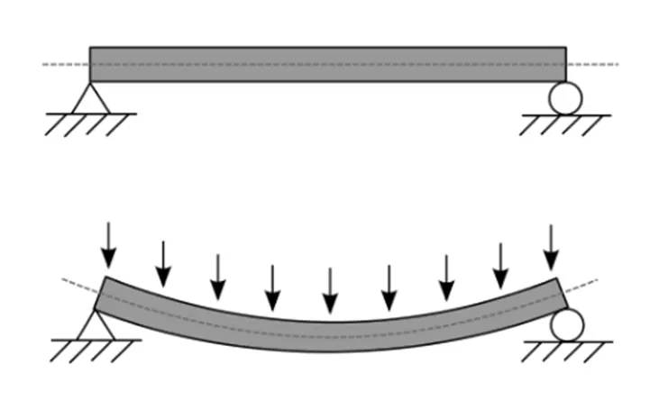
Pure Pending Equation:
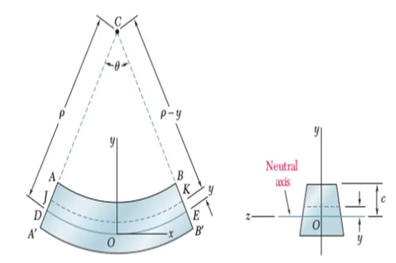
Where, σ – bending stress M- Bending Moment I = Moment of Inertia of area
y = Distance between the neutral axis and the extreme end of the object
E- Young modulus of elasticity R- curvature
Bending Stress Formula
To calculate the bending stress in a beam we use the bending stress formula. Using this formula we can calculate the bending moment along with bending stress.
Bending Stress Assumptions
This formula is derived for the beam which has the following assumptions made:
- The beam is initially straight and has a constant cross-section.
- The beam is composed of homogeneous material and has a longitudinal plane of symmetry.
- The resultant force of the applied load lies in the plane of symmetry.
- The geometry of the entire component is such that buckling rather than bending is the primary cause of failure.
- The elastic limit is never exceeded and 'E' is the same in tension and compression.
- A flat cross-section remains flat before and after bending.
The bending stress formula is:
M/I = σ/y = E/R
where;
- M: Bending moment of the section passing through a point
- I: Moment of Inertia of the section
- σ: Bending stress at a point
- y: Distance between the neutral axis and the extreme end of the object
- E: Modulus of elasticity of the material
- R: Radius of Curvature
To Calculate the section modulus using below formula:
S=I/Y
S = Section Modulus I = Moment of Inertia of area
y = distance between the neutral axis and the extreme end of the object
Section:1
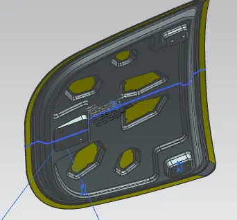
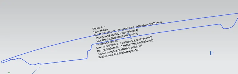
Info Analysis - Section Inertia Analysis
The mass properties are for hollow sections
Sect# CG-XC CG-YC CG-ZC CG-X CG-Y CG-Z SL SA
1 1.325376247 750.382778962 -930.594646950 1.325376247 750.382778962 -930.594646950 2.044864957e+03 40.897834154
Sect# Max-MI Max-X Max-Y Max-Z Min-MI Min-X Min-Y Min-Z Max-RL Min-RL
1 8.264592162e+05 0.000321056 0.980334833 0.197341108 5.301911607e+03 0.000344636 -0.197341215 0.980334803 476.284032770 23.401
323910
Sect#: Number of Section
CG-XC, CG-YC, CG-ZC: Center of Gravity (WCS) [mm]
CG-X, CG-Y, CG-Z: Center of Gravity (Absolute) [mm]
Max-MI: Maximum Principal Moments of Inertia [mm^4]
Max-X, Max-Y, Max-Z: Maximum principal Direction
Min-MI: Minimum Principal Moments of Inertia [mm^4]
Min-X, Min-Y, Min-Z: Minimum principal Direction
Max-RL: Equivalent rectangle section length in Max principal direction [mm]
Min-RL: Equivalent rectangle section length in Min principal direction [mm]
SL: Section Length [mm]
SA: Section Area [mm^2]
Calculation:
Finding distance of ‘y’
Using Y value, we can find neutral axis =Y/2
= 483.98/2
Y=241.99
Section modulus(s) = Imax/Y
=8.264592162e+05/241.99
=3.4152x10^3
Section modulus(s) =Imin/Y
=5.301911607e+03
=2.199x10
Section:2 with increasing the inner surface.
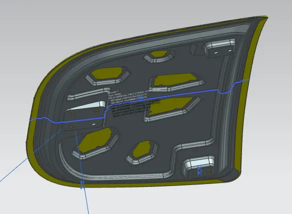
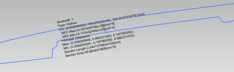
Info Analysis - Section Inertia Analysis
The mass properties are for hollow sections
Sect# CG-XC CG-YC CG-ZC CG-X CG-Y CG-Z SL SA
1 0.000000000 749.372436146 -930.844721620 0.000000000 749.372436146 -930.844721620 2.044137883e+03 40.884247465
Sect# Max-MI Max-X Max-Y Max-Z Min-MI Min-X Min-Y Min-Z Max-RL Min-RL
1 8.257409735e+05 0.000000000 0.980331003 0.197360392 6.175432484e+03 0.000000000 -0.197360392 0.980331003 474.428782306 25.287
667184
Sect#: Number of Section
CG-XC, CG-YC, CG-ZC: Center of Gravity (WCS) [mm]
CG-X, CG-Y, CG-Z: Center of Gravity (Absolute) [mm]
Max-MI: Maximum Principal Moments of Inertia [mm^4]
Max-X, Max-Y, Max-Z: Maximum principal Direction
Min-MI: Minimum Principal Moments of Inertia [mm^4]
Min-X, Min-Y, Min-Z: Minimum principal Direction
Max-RL: Equivalent rectangle section length in Max principal direction [mm]
Min-RL: Equivalent rectangle section length in Min principal direction [mm]
SL: Section Length [mm]
SA: Section Area [mm^2]
Calculation:
Finding distance of ‘y’
Using Y value, we can find neutral axis =Y/2
= 483.98/2
Y=241.99
Section modulus(s) = Imax/Y
=8.257409735e+05 /241.99
=3.4152x10^3
Section modulus(s) =Imin/Y
=6.175432484e+03 /241.99
=2.559x10
CONCLUSION:
As result, Section-2 of the hood is more strength compared to section-1 by using section inertia analysis in Nx-siemens and calculated by section modulus formula.