Roof Design
ROOD DESIGN AND ANALYSIS
Objective:
To design the Front and Rear Roof Rails, along with the Centre and bow Roof Rails according to the master section drawings provided and performing the analysis of the rail designs.
Introduction: (Roof)
An automobile roof or car top is a BIW portion of an automobile that sits above the passenger compartment, protecting the vehicle occupants from sun, wind, rain, and other external elements.
Design of Roof and its Reinforcement:
For this project an A-surface along with the roof rails will be provided and the Roof ditch area along with the Front, Rear Centre and Bow Roof Rails are to be designed.
Design criteria’s to be followed:
Material Selection:
Material selection plays an important part in designing any part. The material for a part is selected keeping in mind the tensile strength, bending, static and dynamic loading that the part would be subjected to. Materials used for the roof and its different reinforcements are mentioned below.
- Roof: SP121AQ T0.7
- Front Roof Rail: SP783AJQ
- Rear Roof Rail: SP783AJQ
- Bow Roofs: SP121BQ
- Centre Roof: SP153-98OPQ
Visibility Criteria:
The visibility criteria of a driver is one of the most important factors when designing the roof. The roof should be designed such that it does not hinder the visibility range of the driver. The ditch area of the roof is design keeping this criterion in mind.
Head Clearance:
This factor is considered when designing the reinforcements of the roof. The reinforcements should be designed in a way that it provides ample headroom clearance for the occupants in the car and does not collide with the head in case the car moves over a bump It should not act as a hindrance for the driver’s rear visibility.
Position of the reinforcements:
- Heat distortion
- Snow load criteria
- Drawibility
- Heat distortion:
- This determines the temperature the roof structure can withstand. The value obtained from the heat distortion prediction formula should be less than 2.7 to be deemed fit for use.
- Snow load criteria:
- This factor is taken into consideration for area with high snowfall which then sets on the car roof. This criterion measures the elasticity of the roof wherein the roof should come back to its original shape and from on the removal of the snow, which in this case acts as the load. The value Qr obtained for the snow load prediction formula should be greater than 3.1 for the design to quality for being used.
- Drawibility:
- The roof and its parts are manufactured using deep drawing process. For this reason, the designs should be manufactural and the design should have a positive draft angle for smooth surface build and also reduced induced stresses in various parts of the reinforcements.
Design of the Roof and Reinforcements
Roof:
- The ditch area of the roof is designed using the master sections provided.
-
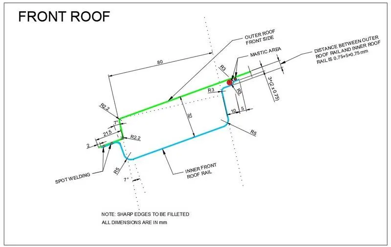
- Front Roof Rail:
- The Front rail is created according to the master section and keeping the visibility criteria in mind.
-
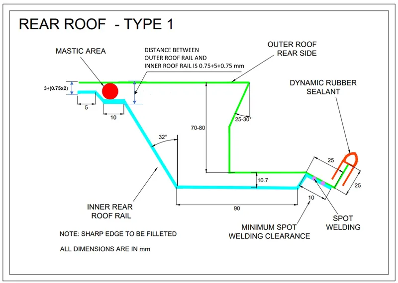
- Rear Roof Rail:
-
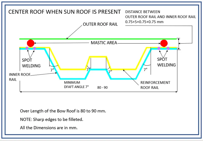
- Centre Roof Rail:
- The Centre Roof Rail provides the roof with additional strength in an adverse case of a roll over thus avoiding injury of the occupants of the vehicle. The reinforcement of the rail is attached with the roof by Mastics and attached to the rail by spot welds. For the Mastics the reinforcement has a clearance of 5mm from the roof.
-
- Bow Roof Rail 1 and 2:
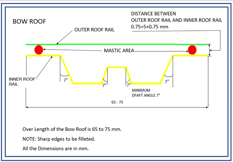
- The bow roof rails also provide the roof with structural strength and their position have to be justified by the Heat Distortion and Snow Load criteria. Both the Bow Rails are attached to the roof by means of Mastics thus a clearance of 5mm from the roof is provided for that purpose.
Design Methodology:
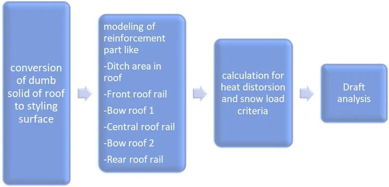
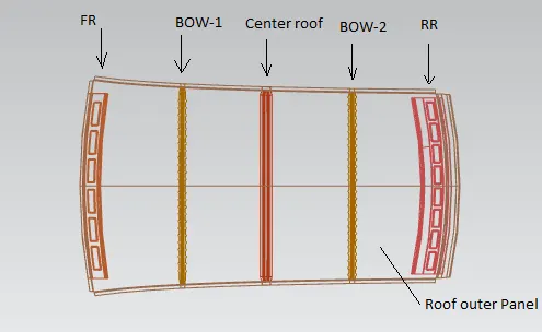
Here we are creating the roof, front and Rear roof rails along with the three reinforcement, by taking pre-designed styling surface as the reference.
The front roof rail and the rear roof rail are the components, where the front and rear sides of the roof are attached, while the other three reinforcement gives enough strength and stiffness to the roof. This assembly includes Roof Outer Panel, Front Roof rail, Rear Roof Rail, Center Reinforcement, Bow Roof 1 and Bow Roof 2. while Front roof rail and rear roof rail is designed with the help of given master section.
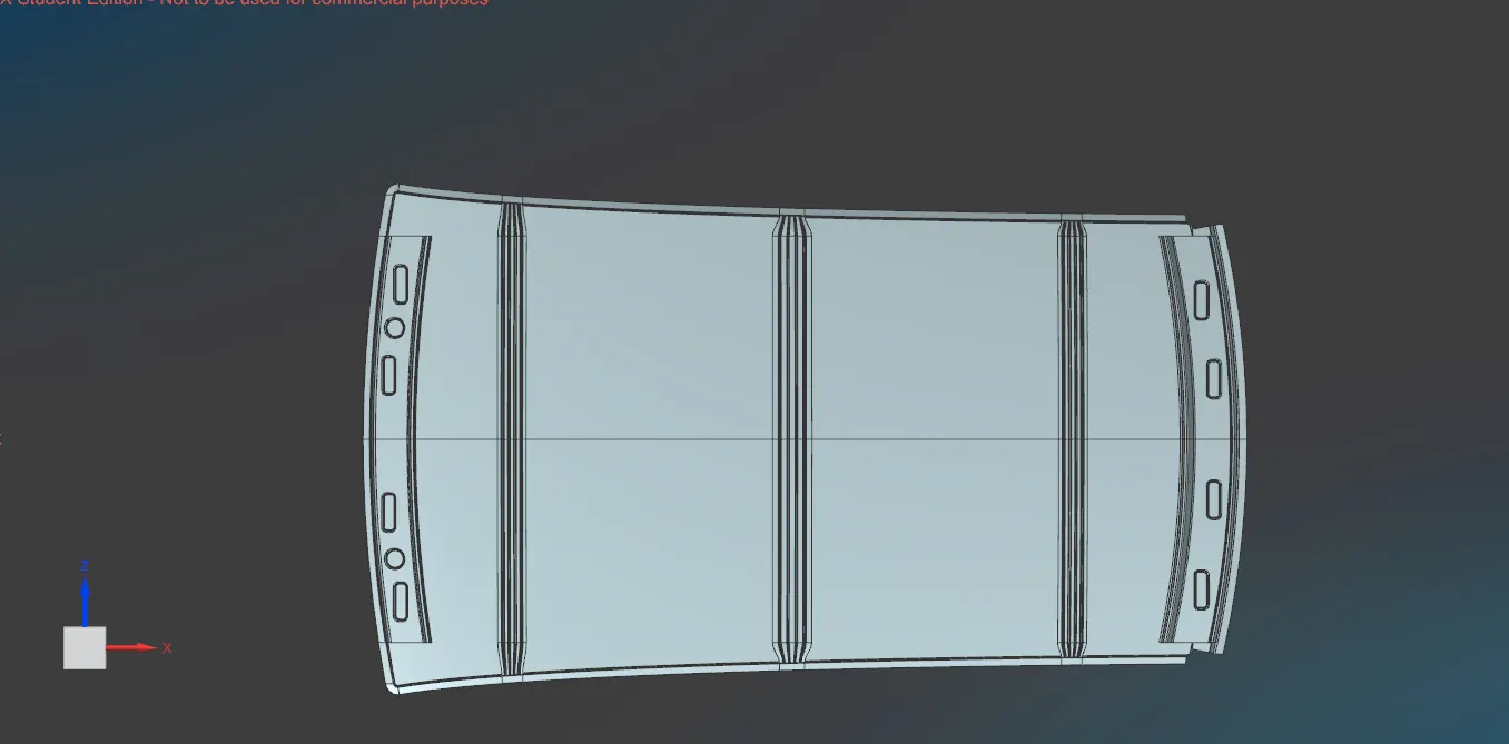
designs of all roof component.
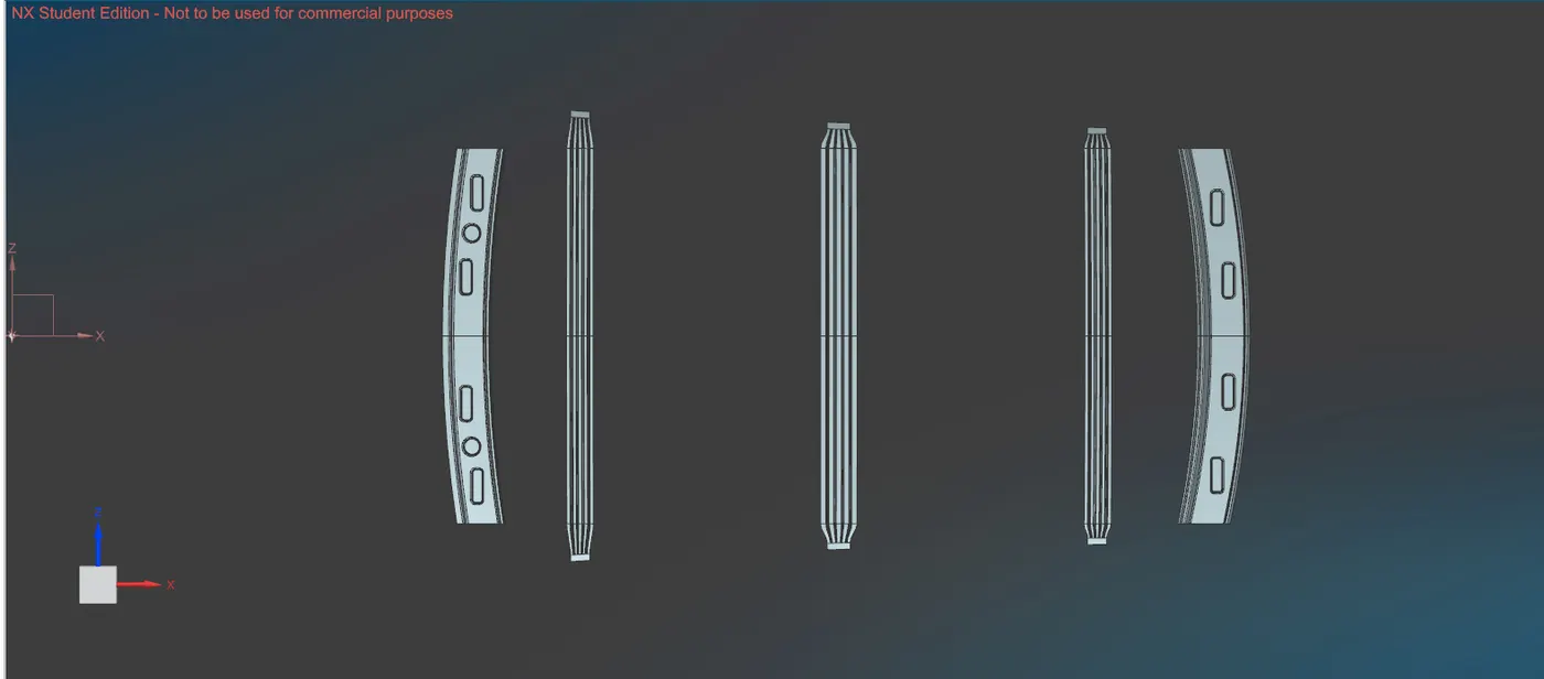
front roof rail thicken component:
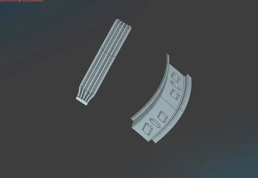
rear roof rail thicken component:
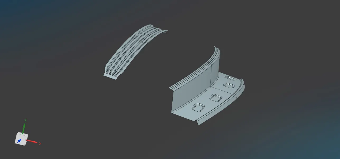
hole assembly of car roof:
calculations:
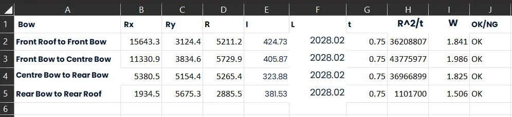
HEAT DISTORTION CRITERA CALCULATION:
W = [1.73 x 10^(-3) x L] + [1.85 x 10^(-8) x (R^2)/t] + [ 1.10x10^(-3) x l] - 2.68
Judgement Condition : OK< 2.7> 3.1
Where:
L = Roof Length in X-Direction[mm](Roof dimension in 0-Y)
R = Roof curvature
R = 2(Rx*Ry)/(Rx+Ry)
Rx = X curvature.
Ry = Y curvature.
t = Roof plate thickness [mm]
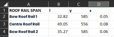
l = Bow Roof Span [mm]
Procedure to measure the parameters-
a. On plane parallel to the top plane draw sketch in which 0Y line is offset by 300 mm (3Y) on both the sides of 0Y line.
b. Draw lines perpendicular to 0Y line passing through point exact midpoint of the two adjacent parts (e.g. midpoint between front rail and bow roof 1)
c. Offset these reference lines on both sides by 100 mm
d. Mark intersection points (red points) of reference line (Yellow lines) and 50 mm offset lines(Black lines).
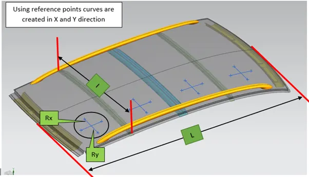
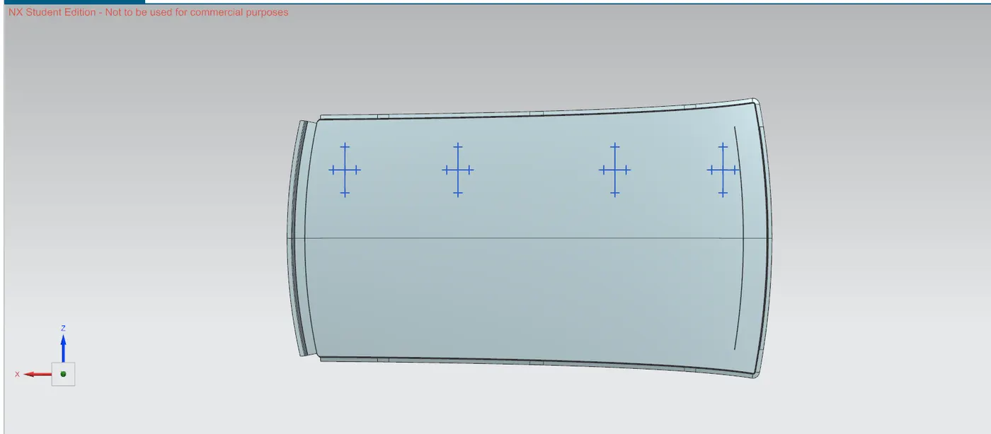
Take all necessary measurements required to calculate W value as per mentioned formula.
table:
SNOW LOAD CRITERIA CALCULATION:
Qr = [Iy x t2] / [α x s x [(Rx + Ry)/2]2 x 10-8]
Where
α = My x Lx2 x 10-12 , My = Y(Ly-Y)
Judgement condition = Qr ≥ 3.1
250 ≤ s ≤ 380
t = Roof plate thickness [mm]
Ly = Distance between the front and rear roof Rails on the Vehicle along with 0Y[mm]
Length of Roof panel with the center point between Roof rail Front /Rear as the front and rear reference point.
Lx = Distance between the Left and Right end of the roof on the Roof BOW [mm] Width of the roof panel exposed on the surface.
Y = Distance from Front Roof Rail to Roof BOW [mm]
s = Distance for which Roof BOW bears divided load [mm]
s = L1/2 + L2/2
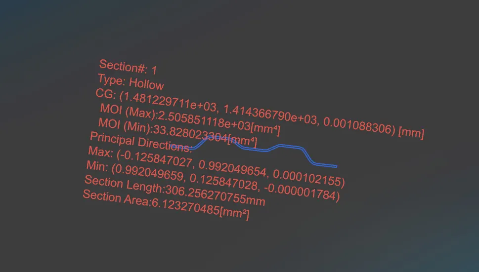
Iy = Geometrical moment of inertia of Roof BOW (Y cross-section) [mm4]
Rx = Lateral direction curvature radius of roof panel Y cross-section on Roof BOW [mm] Roof panel curvature Radius of the Length Lx in Front view
Ry = Longitudinal Direction curvature radius of the Roof panel X cross-section on Roof BOW [mm] Roof panel X curvature radius of length s in Side view
Steps Followed:
- At O-Y axis on perpendicular plane to roof as shown in fig, draw 50 mm lines offset to either side of OY axis line. Now center lines are drawn between each adjacent roof rail edges respectively. Intersection points are marked on the sketch and exit the sketch. Make all geometry in construction lines except the points.
- Project the intersection points in the sketch to roof surface as shown in fig.
- Join the projected curves using arc curves and measure the minimum radius and linear dimension.
- Project the intersection plane bow roof and center roof rail on the horizontal plane to find the moment of inertia of the respective section to find ly values.
- Put all the linear and radial dimension in following formula to calculate Qr value.
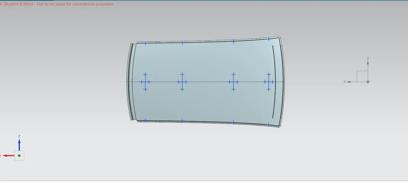
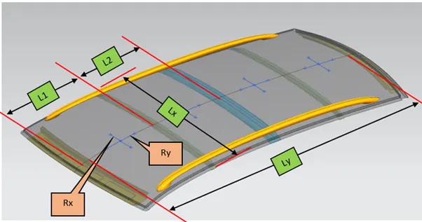
table:

Section Inertia Analysis :
Bow Roof Rail 1:
Centre Roof Rail :
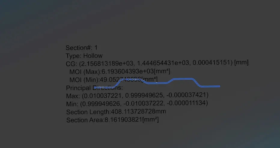
Bow Roof Rail 2:
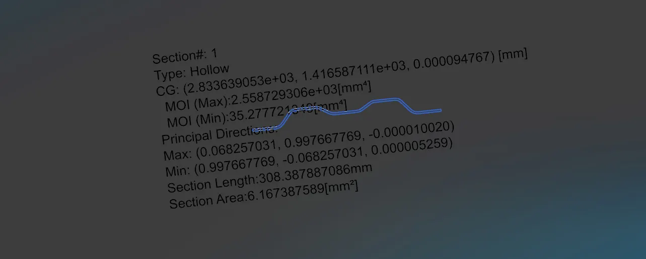
Formula of section Modulus: It may be defined as the ratio of total moment resisted by the section to the stress in the extreme fibre which is equal to yield stress.
Which is equal to yield stress.
Therefore
S=I/y, Where
S= Section modulus (mm^3)
I = Moment of inertia of the section to the stress in the extreme end of the object (mm^4)
Y= Distance between the neutral axis and extreme end of the object (mm).
DRAFT ANALYSIS
1. Roof :
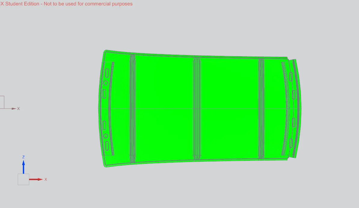
Front Roof Rail& Rear Roof Rail& Centre Roof Rail&Bow Roof Rail 1&Bow Roof Rail 2
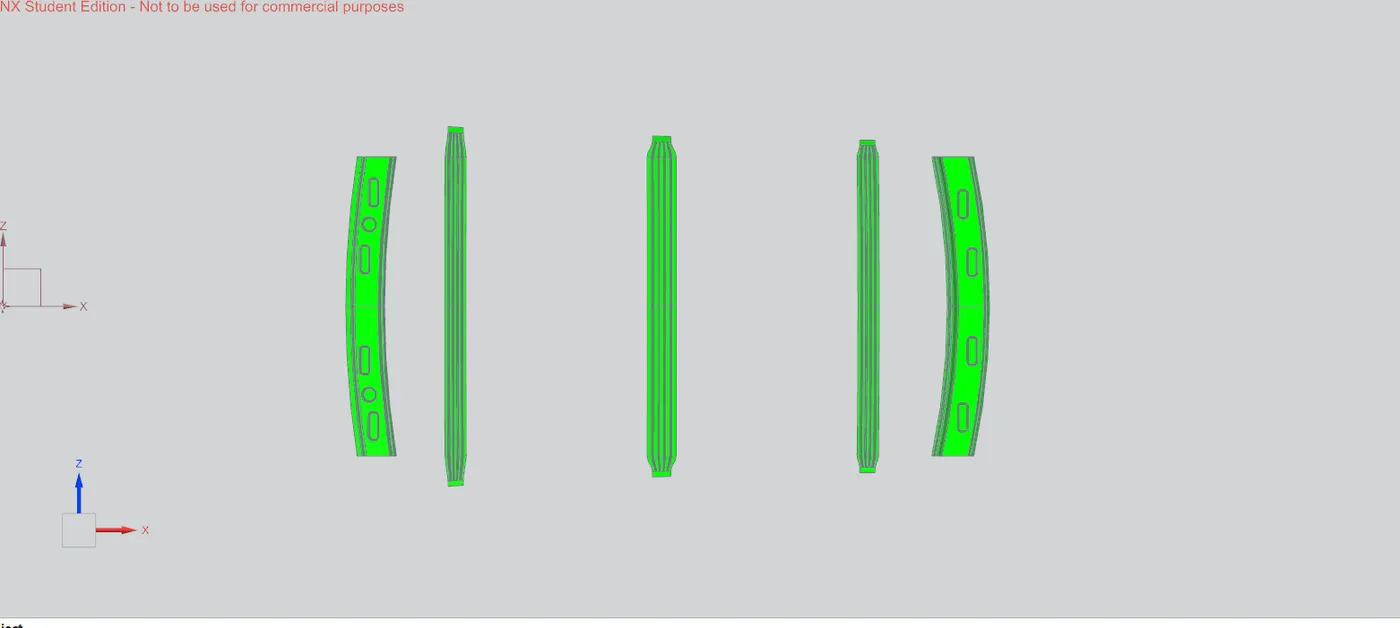
low draftangle area.
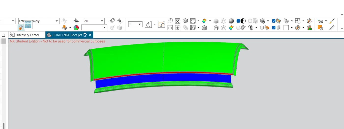
(side core axis has been created over x axix and solve these kind of problem.)
manufacturing techniques.
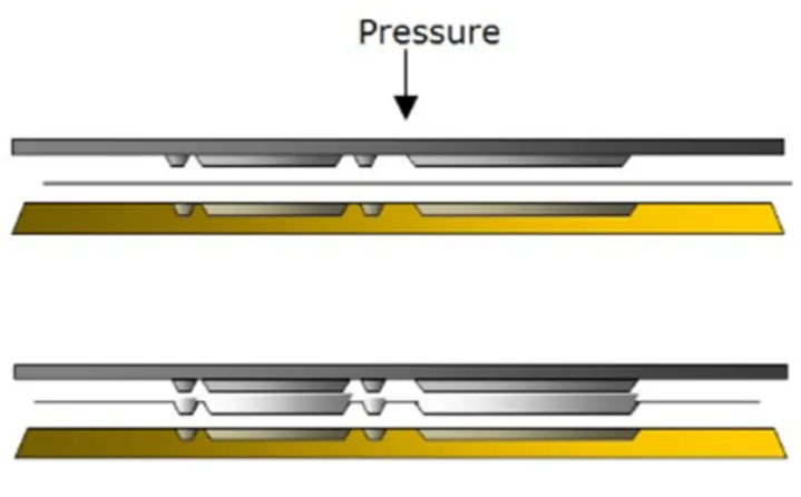
Embossing:
Embossing is a metal forming process for producing raised or sunken designs or relief in sheet material using matched male and female roller dies, theoretically with no change in metal thickness, or by passing sheet or a strip of metal between rolls of the desired pattern.
Cutting and Blanking:
Cutting processes are those in which a piece of sheet metal is separated by applying a great enough shearing force to cause the material to fail.
Blanking is a steel manufacturing process in which a flat, geometric shape is created by feeding a coil of sheet metal into a press and die. In this process, the blank is punched out from the large metal sheet.
Conclusion:
- 1 Roof assembly has been made successfully by following engineering standard, master section and styling surface given by styling team.
- 2 For roof assembly heat distortion criteria& snow load criteria has been successfully passed.
- 3 Draft analysis has been carried out to check manufacturing feasibility.
- 4 Designed part will be submitted to CAE team to carry out further analysis to improve the design.