Roof Design
ROOF DESIGN
Introduction:
The roof is the outer most part and available at top of the car. Which can be performed as protective part from the sun ,wind ,rain and some other external features.
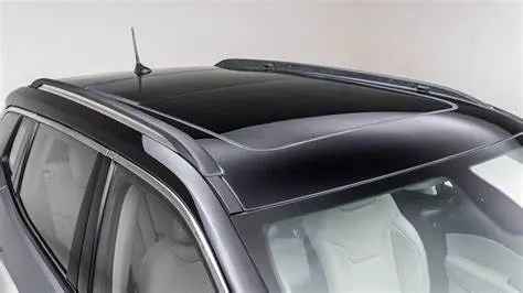
Fig.1
Roof:
An automotive roof consists of the following parts
- The outer panel
- Front roof rail
- Bow roof rail
- Centre roof rail
- Rear roof rail
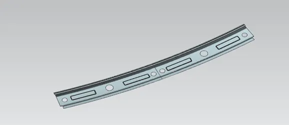
Front roof rail:
The front roof rail is created at the front side of the roof which can be fixed at the top of the roof. Where the head roof clearance and driver visibility is the main parameter to be considered while doing the design. The front roof rail is connected with the outer panel of the roof by use of the mastic seal and the spot welds.
Bow roof rail:
The bow roof rail is the second most part of the car roof which is also be connected with the outer roof panel with the help of the mastic seal and the spot welds. Where the bow roof may increases the strength of the roof.
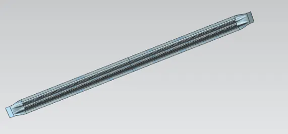
Bow roof rail
Centre roof rail:
The centre roof rail is the centre most part of the roof which may also performs to increase the strength of the roof. Centre roof rail is fixed with the roof outer panel with the help of the mastic seal and the spot welds.

Centre roof rail
Rear roof rail:
The rear roof rail is the last part of the roof which can be fixed at the end of the back side of the roof outer panel. Rear roof rail may also increases the strength of the roof may also performs to connect the back door. And this can be fixed by the help of the mastic seals and the spot welds.
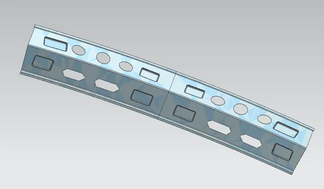
Rear roof rail
Roof images:
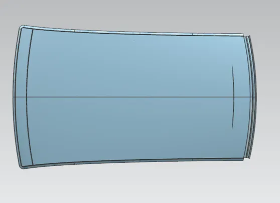
Fig.2
Fig.4
Heat distortion criteria:
Heat distortion temperature is the temperature at which the metal softens and deforms under a specified load. While designing the roof this criteria is to be considered. For this we have to create the bow roof rails when the roof is long and to increase the strength. Where the position of the bow is justified by the curvature study.
Bow -Roof prediction formula
W=[1.73×10^(-3)×L]+[1.85×10^(-8)×(R^2)/t]+[1.10×10^(-3)×I]-2.68
Where,
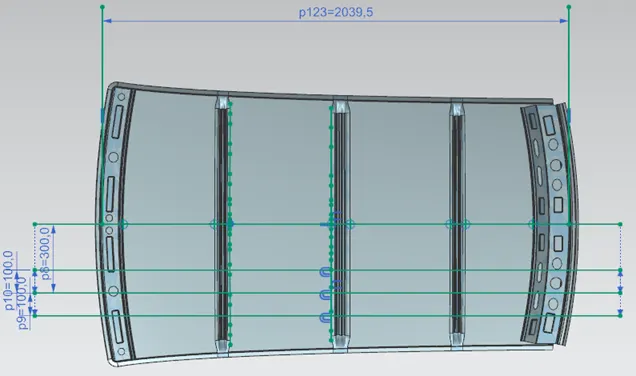
L=Roof length in X-Direction[mm] (Roof dimension in 0-Y)
R=Roof curvature
R=2(Rx*Ry)/(Rx+Ry)
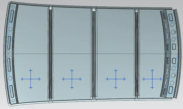
Rx=X curvature
Ry=Y curvature
t=Roof plate thickness
I=Bow roof span [mm]
Judgement condition
OK<2.7
To measure L:
To measure Rx and Ry:
HEAT DISTORTION CRITERIA
|
Roof rails |
Rx (mm) |
Ry (mm) |
Rx*Ry |
Rx + Ry |
R (mm) |
L(mm) |
t (mm) |
I (mm) |
w |
|
FR-Bow 1 |
5734.42 |
2613.16 |
14984957 |
8347.58 |
3590.25 |
2039.5 |
0.75 |
399.7960 |
1.60 |
|
Bow 1-CR |
4910.77 |
6440.46 |
63255235.6 |
11351.23 |
5572.54 |
2039.5 |
0.75 |
444.80 |
2.1 |
|
CR-Bow2 |
3914.41 |
10900.07 |
85334686 |
14814.48 |
5760.22 |
2039.5 |
0.75 |
437.2839 |
2.14 |
|
Bow 2-RR |
3267.68 |
14664.06 |
95834911.2 |
17931.74 |
5344.42 |
2039.5 |
0.75 |
295.5456 |
1.87 |
Here we can see that the roof is completely satisfying the conditions of heat distortions.
Snow load prediction formula:
Snow load is the downward force on a car’s roof by the weight of accumulated snow and ice. The roof can fail if the snow load exceeds the weight of the roof was designed to shoulder. If the roof was poorly designed or constructed.
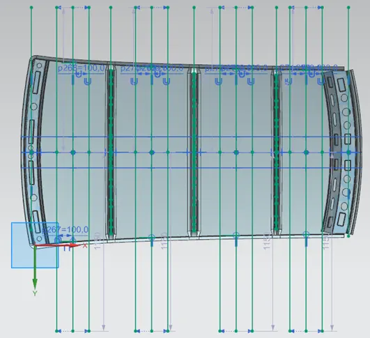
To measure Lx and Ly:
To measure Rx and Ry:
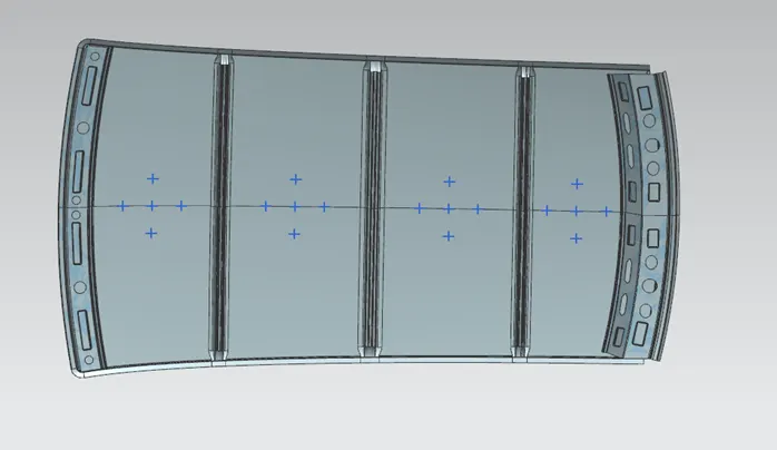
HEAT DISTORTION CRITERIA
|
Roof rail |
Iy (mm) |
Lx (mm) |
Ly (mm) |
L1 (mm) |
L2 (mm) |
Rx (mm) |
Ry (mm) |
t (mm) |
Y (mm) |
S |
My |
α |
Qr |
Result |
|
FR-Bow 1 |
1261.71 |
1148.0 |
1962.6 |
491.3 |
515.5 |
4497.03 |
3311.26 |
0.75 |
491.3 |
503.4 |
72849.69 |
0.9526 |
9.70 |
OK |
|
Bow 1-CR |
3219.34 |
1096.5 |
1962.6 |
515.5 |
510.0 |
3792.07 |
144756.29 |
0.75 |
1006.8 |
512.75 |
962299.44 |
1.1569 |
0.05 |
NOK |
|
CR-Bow 2 |
1270.23 |
1066.6 |
1962.6 |
510.0 |
445.8 |
4295.72 |
15981.24 |
0.75 |
1516.8 |
477.9 |
676189.44 |
0.7692 |
1.89 |
NOK |
It is observed that the roof is satisfying the condition only in the area between bow roof 1 and centre roof, in the other areas it is not satisfying the condition. So in order to strengthen the roof at these areas embosses are created on the outer roof.
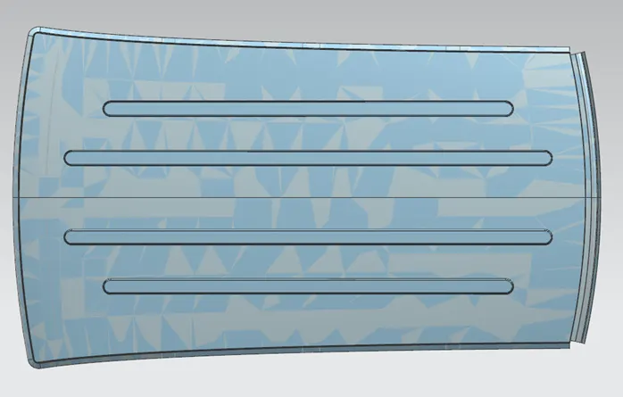
Section modulus study of the section of the roof rails:
The section modulus of the cross-sectional shape is of significant importance in designing of structures. It is a direct measure of the strength of the structure. It is a direct measure of the strength of the structure.
A structure that has a larger section modulus than another will be stronger and capable of supporting greater loads.
Section modulus (S)=I/Y
Where,
I=Moment of inertia (mm^4)
Y=Distance between the neutral axis and the extreme end of the object (mm)
Front roof rail:
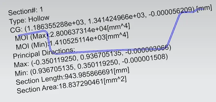
Inertia analysis
I=1410.52mm^4
Y=129.1798/2
S=218.38mm^3
Bow roof 1:
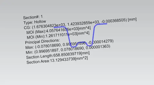
Inertia analysis
I=1261.71mm^4
Y=65.9001/2
S=382.91mm^3
Centre roof rail:
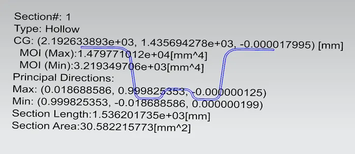
Inertia analysis
I=3219.34mm^4
Y=81.9394/2
S=785.78mm^3
Bow roof 2:
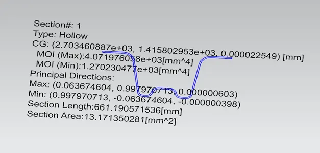
Inertia analysis
I=1270.23mm^4
Y=65.9701/2
S=385.09mm^3
Rear roof rail:
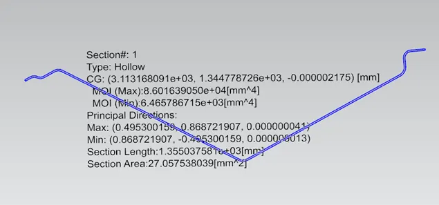
Inertia analysis
I=6465.78mm^4
Y=191.3488/2
S=675.81mm^3
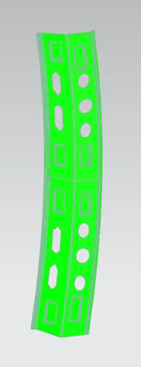
DRAFT ANALYSIS:
Roof top
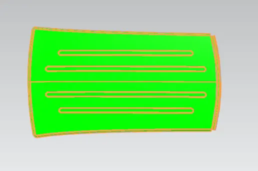
Front roof rail
Bow roof 1

Centre roof rail

Bow roof 2

Rear roof rail
Conclusion:
Hence the Roof design is done as per the given master sections. And all the analysis are done and the result is satisfied.