Roof Design
Roof:
The roof is an upper part of the car that sits above the passenger compartment, protects the vehicle occupants from the sun, wind, rain, and other external elements.
Heat Distortion Criteria:
During summers in the Middle East, the heat radiating from the sun causes the roof of the car to change in the metallic regions. Heat distortion criteria indicate what temperature materials start to "soften" when exposed to a fixed load at elevated temperatures.
Where,
L = Roof Length in X- Direction (mm) [Roof Dimension with OY]
R = Roof Curvature =
Where,
t = Roof Plate Thickness (mm)
l = Bow roof Thickness (mm)
Snow Load Criteria:
During Winter Season the snow gets clogged over the Top areas of the car and the snow has some mass on it. The roof can fail if the snow load exceeds the Capacity of the Roof was designed to sustain.
Where,
Where
t = Roof Plate thickness (mm)
Y = Distance from front roof rails to Roof Bow (mm)
S = Distance for which Roof bow bears divided load (mm) =
Section Modulus:
Section modulus is a geometric property for a given cross-section used in the design of beams. Other geometric properties used in design include area for tension, radius of gyration for compression, and moment of inertia for stiffness. The Section modulus is defined as
Where
S = Section Modulus
I = Moment of Inertia
y = Distance from the neutral axis to any given part.
Procedure:
- Checking the Class –A surface:
- After the file is opened, the roof part is not joined together but as the individual surfaces.
- It is also seen as the surface is perfectly symmetrical in shape which helps us to work on the half of the portion and reflect it which creates the whole roof.
- Creating the Front roof Rail:
- Offset the roof to 2.7mm and split it with a distance of 5mm.
- Similarly, create an offset of 4.7mm and cut it.
- Now create a base offset of 32mm from the roof.
- Create the respective sweeps for these offsets and trim them together.
- Give the Edge fillets to it.
- Creating the Rear roof Rail:
- For the rear roof, rail follows a similar procedure as the front roof and the values for it are given in the diagram.
- Make sure that the Rear roof has a positive draft angle.
- Creating the Center Reinforcement:
- The Center Reinforcement is attached at the center yet below the roof.
- To create the center reinforcement as per the diagram, we use the offset and select the parallel curve option and give an offset value of 50mm on both sides and create a cut on the offset.
- Now create the part as per the design standards and make sure that the offset is given considering the thickness of the component.
- Creating the Bow roofs:
- 3 bow roofs are created to give strength to the roof.
- Follow the same method as with the center reinforcement to create the bow roof.
- Now, after the bow roof is created. The mastic points need to be created.
- Use the parallel curve and connect the outer edge and parallel curve to cut the elements.
- Checking the Heat Distortion criteria:
- To calculate the Heat distortion criteria, we have to take note of few values and note it down.
- To note down, first, we need to create a sketch.
- Create a line at the center of the roof part in the 0-Y axis and then draw another line with a distance of 300mm.
- Now create the line with a distance of 100 on both sides at the line which is at 300mm.
- Now create the line between the rails in the X direction and create 2 lines with a distance of 100mm on both sides.
- Now create a point coinciding with both the lines.
- Checking the Snow Load Criteria:
- To calculate the Snow Load criteria, we have to take note of few values and note it down.
- To note down, first, we need to create a sketch.
- Create a line at the center of the roof part in the 0-Y axis.
- Now create the line with a distance of 100 on both sides.
- Now create the line between the rails in the X direction and create 2 lines with a distance of 100mm on both sides.
- Now create a point coinciding with both the lines.
- Checking the Section Modulus:
- To check the section modulus, we need to create the intersection in the Y-axis.
- After the intersection is done, fill the surface with the intersection created.
- Select Measure Inertia option to measure the 2D inertia of the surface created.
- Note down the values.
-
Calculation:
Heat Distortion Criteria:
-
Center Reinforcement and second Bow roof rail:
W = [ 1.73 × 10 - 3 × L ] + [ 1.85 × 10 - 8 × ( R 2 t ) ] + [ 1.10 × 10 - 3 × l ] - 2.68 Known values
L= 2033.705 mm
t = 0.75mm
R x R y l = 239.409mm (by measuring the distance between the bow roofs)
R =
2 ( R x × R y ) R x + R y = 2 ( 4134.558 × 9799.199 ) 4134.558 + 9799.199 = 2 ( 2907.712 ) R 2 t = ( 5815.4246 ) 2 0.75 = 33819163.278285516 0.75 W = [ 1.73 × 10 - 3 × 2033.705 ] + [ 1.85 × 10 - 8 × ( 45092217.70438 ) ] + [ 1.10 × 10 - 3 × 239.409 ] - 2.68 W = 1.9358
For Second Bow roof to Third Bow Roof:
W = [ 1.73 × 10 - 3 × L ] + [ 1.85 × 10 - 8 × ( R 2 t ) ] + [ 1.10 × 10 - 3 × l ] - 2.68 Known values
L= 2033.705 mm
t = 0.75mm
R_x= 3637.271mm (By measuring the arc created)
R_y= 12391.81mm (By measuring the arc created)
l = 146.325mm (by measuring the distance between the bow roofs)
R =
2 ( R x × R y ) R x + R y = 2 ( 3637.271 × 12391.81 ) 3637.271 + 12391.81 = 2 ( 2811.912 ) R 2 t = ( 5623.8247 ) 2 0.75 = 31627404.256 0.75 W = [ 1.73 × 10 - 3 × 2033.705 ] + [ 1.85 × 10 - 8 × ( 42169872.3417 ) ] + [ 1.10 × 10 - 3 × 146.325 ] - 2.68 W = 1.7794
For the third Bow Roof and Rear Rail:
W = [ 1.73 × 10 - 3 × L ] + [ 1.85 × 10 - 8 × ( R 2 t ) ] + [ 1.10 × 10 - 3 × l ] - 2.68 Known values
L= 2033.705 mm
t = 0.75mm
R x R y l = 218.768mm (by measuring the distance between the bow roofs)
R =
2 ( R x × R y ) R x + R y = 2 ( 3229.674 × 14924.424 ) 3229.674 + 14924.424 = 2 × ( 2655.104 ) R 2 t = ( 5310.2086 ) 2 0.75 = 28198315.37551396 0.75 W =
[ 1.73 × 10 - 3 × 2033.705 ] + [ 1.85 × 10 - 8 × ( 37597753.8340 ) ] + [ 1.10 × 10 - 3 × 218.768 ] - 2.68 W = 1.7745
-
Snow Load Criteria:
y- Value:
-
For First Bow Roof to Second Bow Roof:
Q r = I y × t 2 α × S [ R x + R y 2 ] 2 × 10 - 8 Known Values:
L x L y I y y = 339.292 mm
R x R y α = M y × ( L x ) 2 × 10 - 12 Where
M y = Y ( L y - Y ) α = Y ( L y - Y ) × ( L x ) 2 × 10 - 12 = 339.292 ( 2033.705 - 339.292 ) × ( 1073.733 ) 2 × 10 - 12 S = L 1 2 + L 2 2 Where
L 1 L 2 S=
L 1 2 + L 2 2 = 339.292 + 253.75 2 Q r = I y × t 2 α × S [ R x + R y 2 ] 2 × 10 - 8 Q r = 4352 × ( 0.75 ) 2 0.6628 × 296.521 × [ 4195.902 + 10174.952 2 ] 2 × 10 - 8 Q r For Second Bow Roof to Third Bow Roof:
Q r = I y × t 2 α × S [ R x + R y 2 ] 2 × 10 - 8 Known Values:
L x L y I y y = 253.75 mm
R x R y α = M y × ( L x ) 2 × 10 - 12 Where
M y = Y ( L y - Y ) α = Y ( L y - Y ) × ( L x ) 2 × 10 - 12 = 253.75 ( 2033.705 - 253.75 ) ( 1058.452 ) 2 × 10 - 12 S = L 1 2 + L 2 2 Where
L 1 L 2 S=
L 1 2 + L 2 2 = 253.75 + 357.53 2 Q r = I y × t 2 α × S [ R x + R y 2 ] 2 × 10 - 8 Q r = 4352 ( 0.75 ) 2 0.506 × 305.64 [ 4329.6 + 13410.404 2 ] 2 × 10 - 8 Q r For Second Bow Roof to Third Bow Roof:
Q r = I y × t 2 α × S [ R x + R y 2 ] 2 × 10 - 8 Known Values:
L x L y I y y = 357.53 mm
R x R y α = M y × ( L x ) 2 × 10 - 12 Where
M y = Y ( L y - Y ) α = Y ( L y - Y ) × ( L x ) 2 × 10 - 12 = 357.53 ( 2033.705 - 357.53 ) × ( 1058.437 ) 2 × 10 - 12 Here, S value can’t be calculated as the
L 2 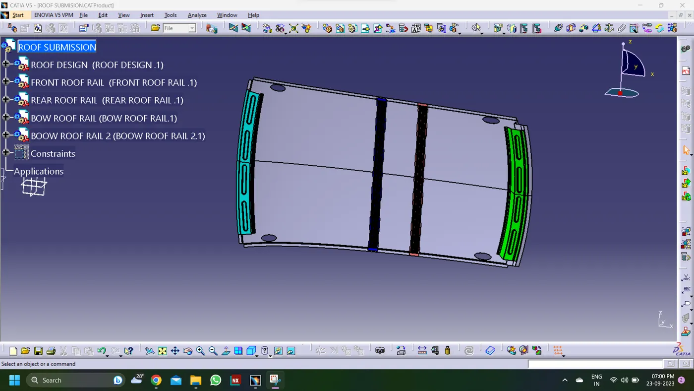
-
Learning Outcome:
1. Learned how to create rails as per the design.
2. Learned how to calculate and what are the criteria for the Heat Distortion, Snow Load conditions.