Roof Design
Roof Design:
Aim:
To create an Assembly by developing the essential flanges for the outer roof and creating the reinforcements.
About Roof:
An automobile roof or car top is the portion of an automobile that sits above the passenger compartment, protecting the vehicle occupants from sun, wind, rain, and other external elements.
Desin Consideration in Roof:
- Visibility criteria
- Head room clearance
- Bow roof rail and center roof rail position
- Heat distortion and snow load calculation
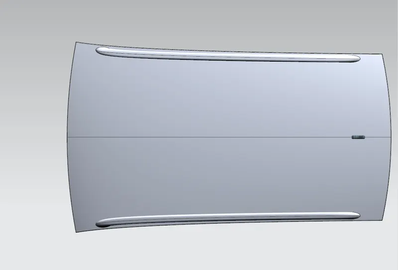
Given Outer Pannel:
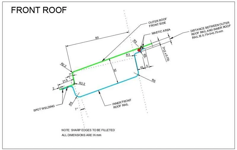
Front Roof Rail Master Section:
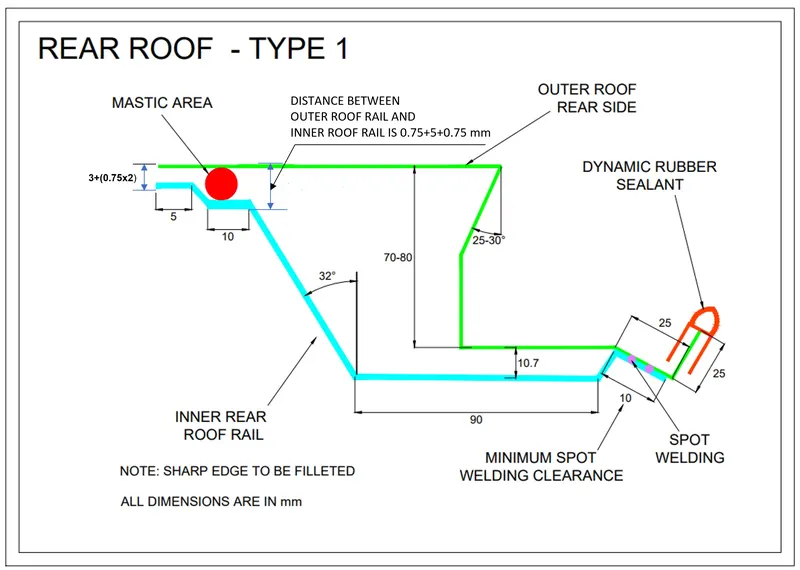
Rear Roof Rail Master Section:
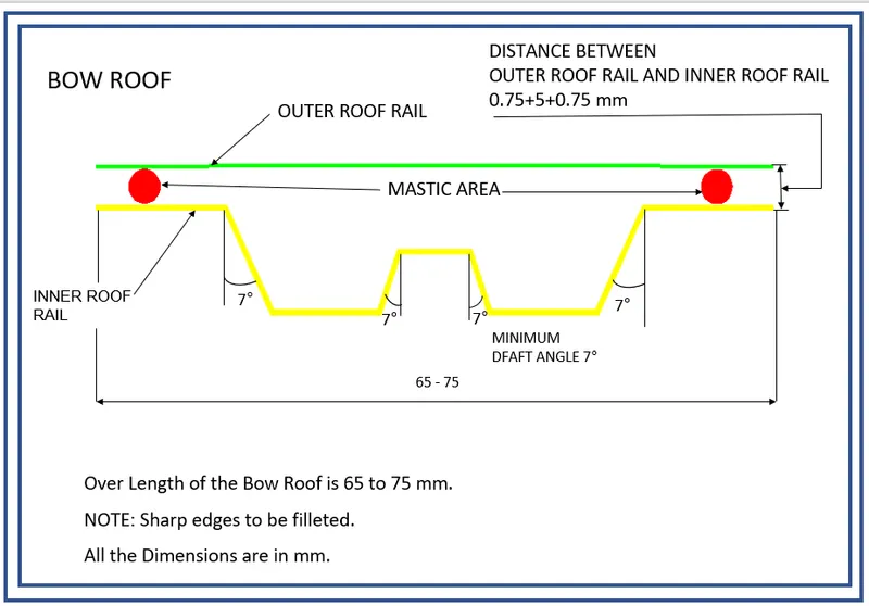
Bow Roof Rail Master Section:
Center Roof Rail Master Section:
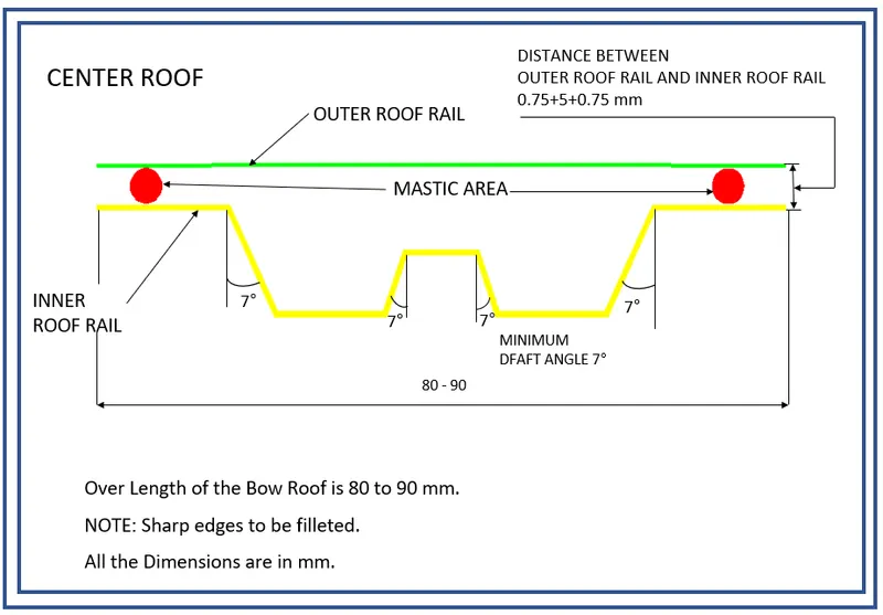
Roof Design:
Part Structure:
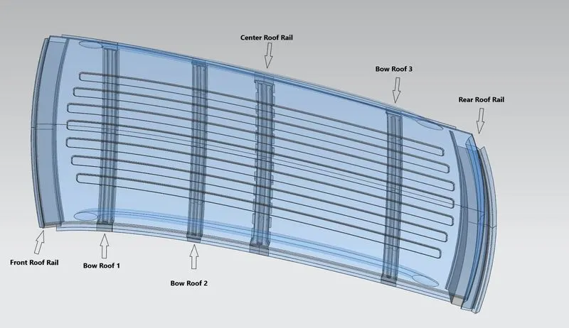
It provides all information of roof assembly and location of roof rails. Roof rails are used to carry bulky cargo or sporting equipment overhead that can use special roof mounts which can be fixed on to these rails. They are a modern version of the old 'luggage carrier' except that they are designed to be mounting points rather than carriers.
The Reinforcement Are Classified According to their Positions:
1. Front Roof Rail
2. Bow Roof 1
3. Bow Roof 2
4. Center Roof Rail
5. Bow Roof 3
6. Rear Roof Rail
Front Roof Rail;
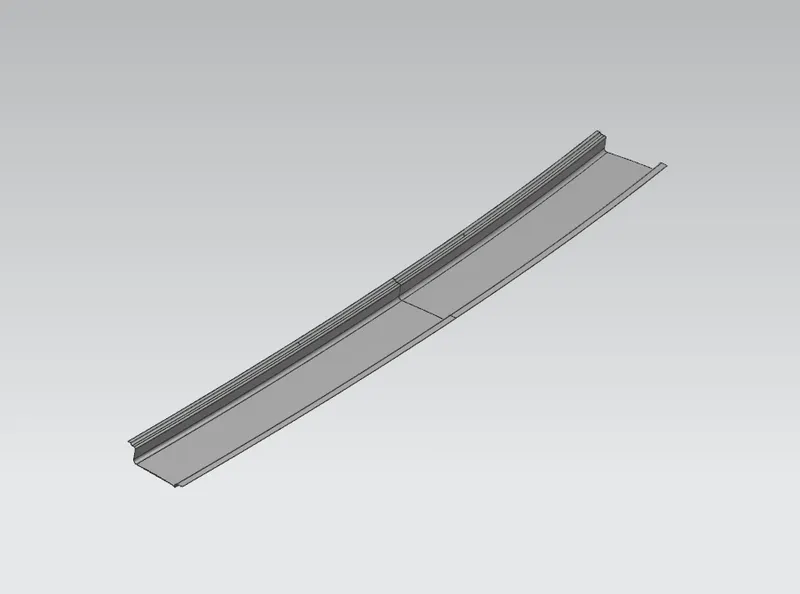
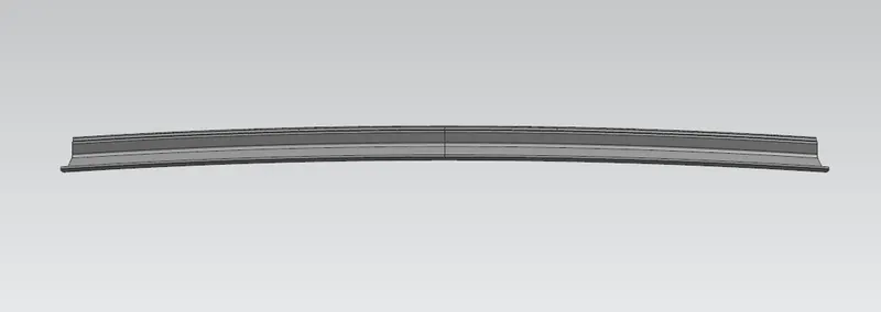
- The front roof rail is created as per master section
- This front roof rail is used to connect the outer roof and wind shield
- 85mm minimum and it varies project to project. Small rubber kind material called as Mastics which is used to joint the roof outer and front roof rail.
Rear Roof Rail;
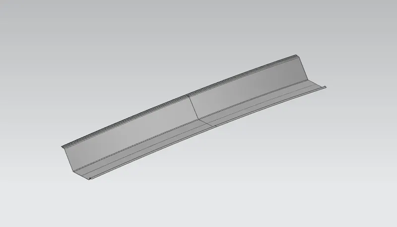
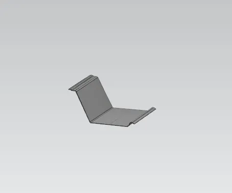
- The rear roof rail is created as per the master section
- It is place where back door in mounted. It is very important to provide rear room head clearance & rear visibility criteria for safety and comfort.
- The Rear Roof Rail Is Used To Connect The Outer Roof Rail .
Center Roof RAil;
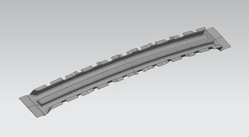
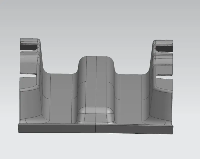
- This centre roof rail is created as per the master section given
- Mastic cutouts are made to place the mastic and the centre roof rail and outer roof will be stick together
- The corner of the centre roof rail and the outer roof flage will be spot welded.
Bow Roofs;
Bow Roof 1:
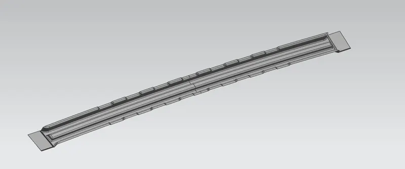
Bow Roof 2:
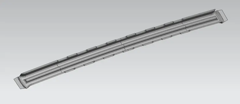
Bow Roof 3
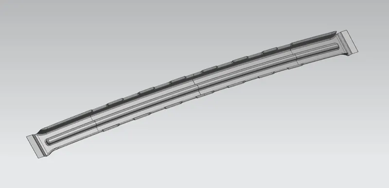
- This bow roof rail is created as per the master section given.
- Mastic cutouts are made to place the mastic and the bow roofs rail and outer roof will be stick together.
- This is used to add some strength to the roof area
- Fillets are used to clear the sharp edges
- This is the part of roof which provide strengthen to the roof which have some mastic region and some embosses area.
BOW ROOF PREDICTION FORMULA:
W = [1.73 x 10^(-3) x L] + [1.85 x 10^(-8) x (R^2)/t] + [ 1.10x10^(-3) x l] - 2.68
Where,
L = Roof Length in X-Direction[mm](Roof dimension in 0-Y)
R = Roof curvature
R = 2(Rx*Ry)/(Rx+Ry)
Rx = X curvature
Ry = Y curvature
t = Roof plate thickness [mm]
l = Bow Roof Span [mm]
Judgement Condition:
Ok≤ 2.7
W= Value should lie between 2.7>3.5
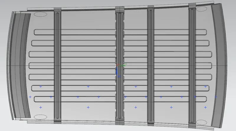
This Points are Created BY offsetting by 300 mm From the center of the Roof
Calculation:
|
S.no |
Bow’s |
Rx |
Ry |
R |
I |
L |
t |
W |
Ok\NG |
|
1 |
FRR – BR1 |
1913.054 |
1955.793 |
1934.187 |
184.2 |
2028.30 |
0.70 |
1.3797 |
Ok |
|
2 |
BR1 – BR2 |
4166.030 |
4078.216 |
4121.6553 |
327.7 |
2028.30 |
0.70 |
1.6383 |
Ok |
|
3 |
BR2 – CTR |
4709.493 |
4591.121 |
4609.4098 |
220.6 |
2028.30 |
0.70 |
1.6331 |
Ok |
|
4 |
CTR – BR3 |
3828.8299 |
3850.1086 |
3837.1086 |
520.6 |
2028.30 |
0.70 |
1.7907 |
Ok |
|
5 |
BR3 - RRR |
3153.450 |
3196.648 |
3174.9061 |
254.9 |
2028.30 |
0.70 |
1.3757 |
Ok |
Calculation Section Modulus: -
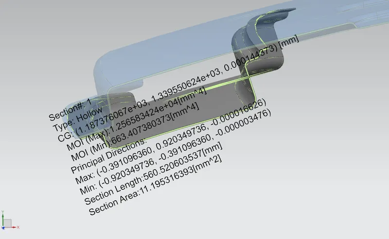
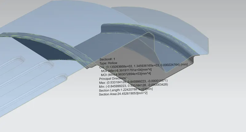
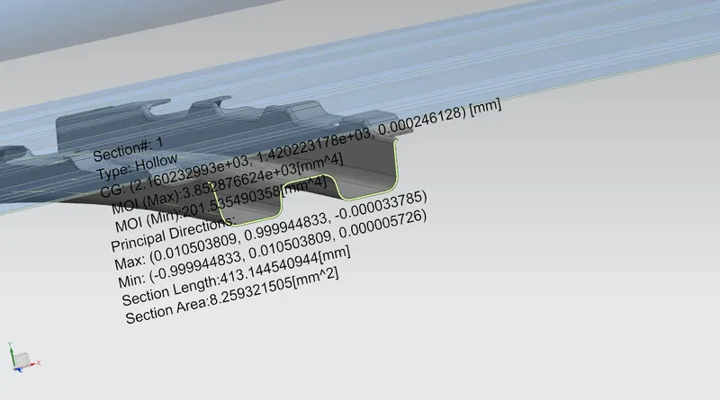
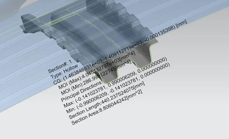
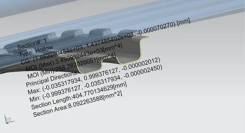
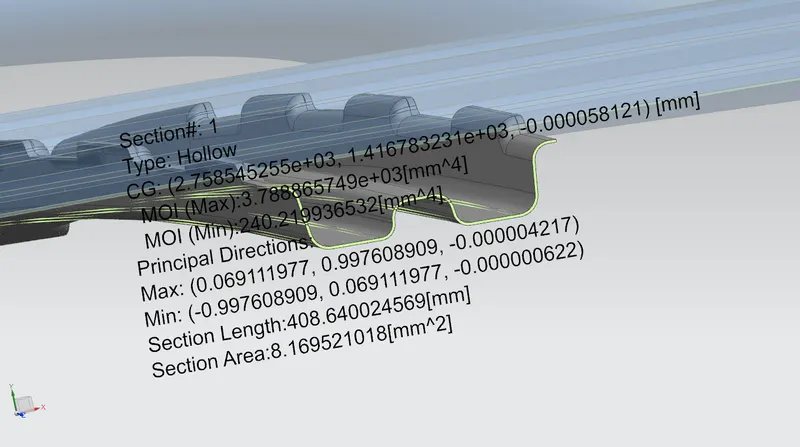
Section modulus is the direct Measure of Strength of a beam. Higher the Section Modulus higher will be the Resistance to Bending. In general, it can be stated as the strength of a section under bending.
MOI Of Front Roof Rail;
MOI of Rear Roof Rail;
MOI of Center Roof Rail;
MOI of Bow Roof 1:
MOI of Bow Roof 2:
MOI of Bow Roof 3:
Snow Load Prediction Formula:
Qr = [Iy x t2] / [α x s x [(Rx + Ry)/2]2 x 10-8]
Where,
α = My x Lx2 x 10-12 , My = Y(Ly-Y)
t = Roof plate thickness [mm]
Ly = Distance between the front and rear roof Rails on the Vehicle along with 0Y[mm]
Length of Roof panel with the center point between Roof rail Front /Rear as the front and rear reference point.
Lx = Distance between the Left and Right end of the roof on the Roof BOW [mm]
The width of the roof panel is exposed on the surface.
Y = Distance front Front Roof Rail to Roof BOW[mm]
s = Distance for which Roof BOW bears divided load [mm]
s = L1/2 + L2/2
Iy = Geometrical moment of inertia of Roof BOW (Y cross-section )[mm4]
Rx = Lateral direction curvature radius of roof panel Y cross-section on Roof BOW [mm]
Roof panel curvature Radius of the Length Lx in Front view
Ry = Longitudinal Direction curvature radius of the Roof panel X cross-section on Roof BOW [mm]
Roof panel X curvature radius of length s in Side view
Judgment condition.
Qr ≥ 3.1
250 ≤ s ≤ 380
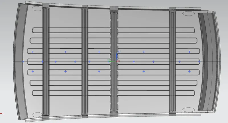
the Points Are Created in the mid of the roof.
Calculation:
|
SNo |
Bows |
ly |
Lx |
Ly |
Y |
S |
Rx |
Ry |
T |
Qr |
|
|
1. |
FRR – BR1 |
2650.8 |
0.6677 |
1157.913 |
2028.30 |
285.8 |
342.2 |
1981.897 |
2036.29 |
0.70 |
140.847 |
|
2. |
BR1 – BR2 |
3768 |
0.7984 |
1108.7 |
2028.30 |
398.6 |
348.4 |
4254.74 |
4230.57 |
0.70 |
36.875 |
|
3. |
BR2 – CTR |
3671.85 |
0.5990 |
1077.55 |
2028.30 |
298.2 |
448.3 |
5441.27 |
3303.06 |
0.70 |
35.046 |
|
4. |
CTR – BR3 |
3820.8 |
0.9545 |
1056.2 |
2028.30 |
592.4 |
492.8 |
4093.619 |
4375.665 |
0.70 |
22.9161 |
|
5. |
BR3 - RRR |
- |
0.6883 |
1040.871 |
2028.30 |
387.2 |
387.2 |
3325.73 |
4264.749 |
0.70 |
-- |
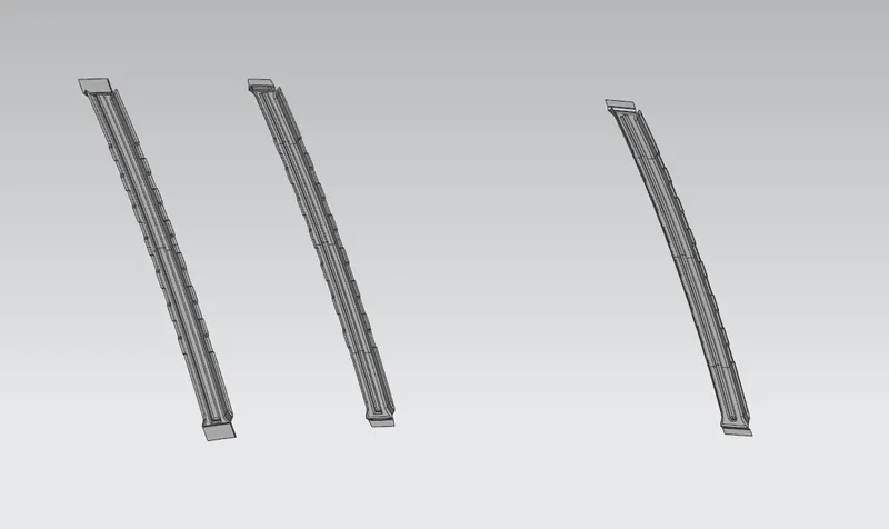
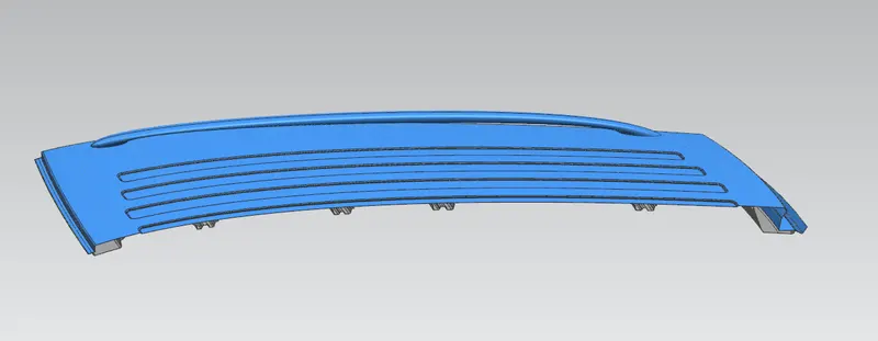
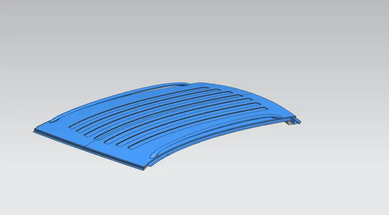
Different View of Assembly:
Intersection View:
Isometric view:
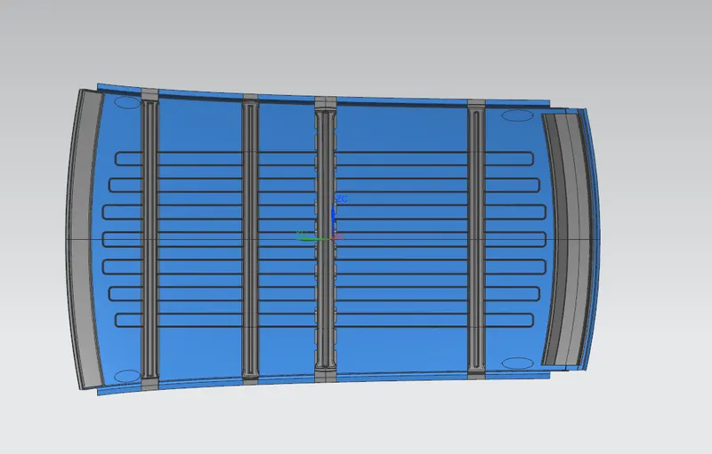
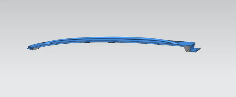
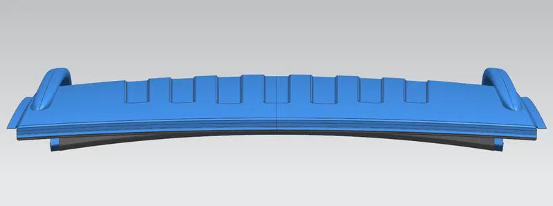
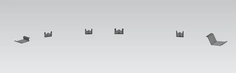
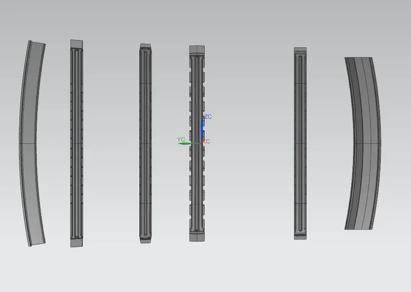
Ive Attached the part files and images of calculation of bow roof prediction and Snow Load prediction.
Thank You.