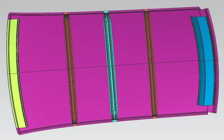
Roof Design
- Roof assembly
Created a main assembly file and created all files mentioned below. Using Mirror and Thicken command, all geometries are designed.
- Outer roof Design
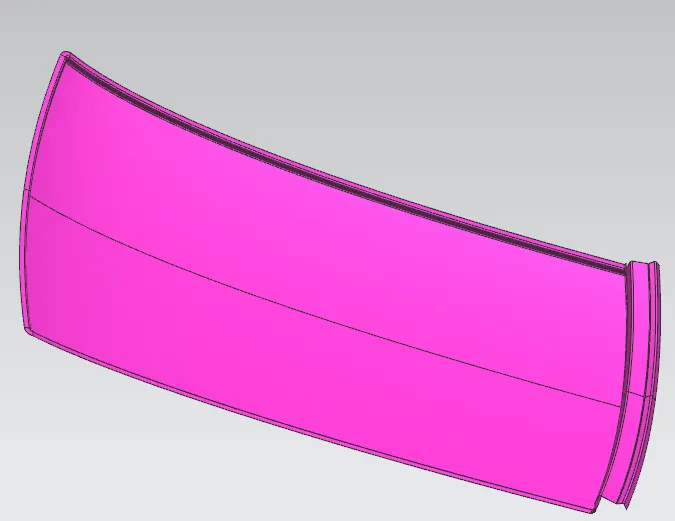
1) Imported class A file into this file. Using Extract and trim command, surface quality is improved. Using master sections, Created flanges with 7 degree draft angle and side ditch area also followes front roof rail flange design.
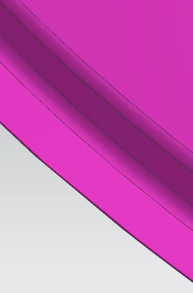
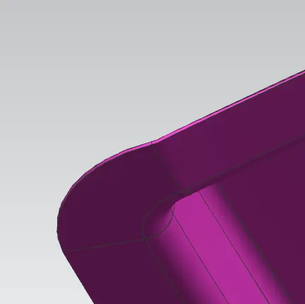
2) Created rear roof flanges following rear roof rail master sections.
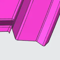
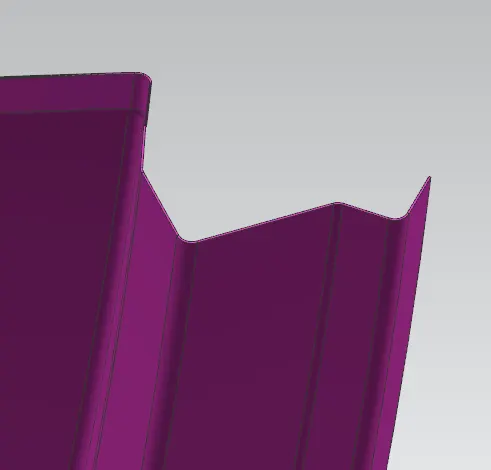
3) Extended the mirroring surfaces by 5mm and trimmed with YZ plane for better continuity in mirror. Mirrored the roof surface and thickened with thickness of 0.75mm. Examined the geometry for uneven surface continuity and interfared surfaces.
- Front roof rail
Using front roof rail master section, created offset by 32mm and required flanges are designed with face blends of 5mm. Extended the mirrored surface and trimmed, mirrored and sewed the surface. Thickened the surface by 0.75mm and added some edge blends.The distance maintained between outer roof and front rood rail is 0.2mm.

- Rear roof rail
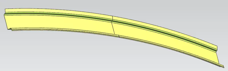
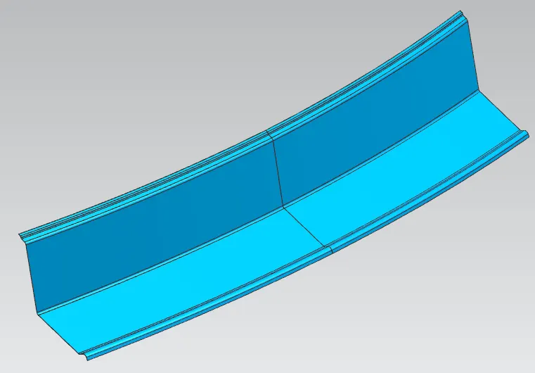
Using rear roof rail master section, Created offset of 10.7mm which consist of 0.2mm of mastic area. Also offseted the 4.5mm and 6.5mm for upper area flanges. Joined the flanges by Studio surface command and followed same method for avoiding the inferance of surface.(Extending the mirroring surface by 5mm and trimming with YZ plane.) Thickened the surface by 0.75mm.
- Center roof rail
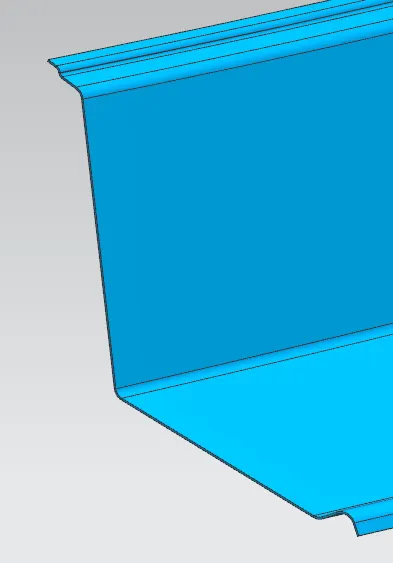
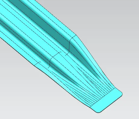
Center roof is designed by not considering the Sunroof. Here the center roof is designed by using intersection curve made with the datum plane placed on curve with 50% arc length. Following the master sections, all the design have done considering th total width of roof rail as 80mm. Side ditch area is extracted using WAVE geometry and trimmed at the length of 40mm. Trimmed the rail surface wrt datum co ordinate system by 450mm and joined with side flange using studio surface by giving G1 continuity.
- Bow roof rail 1 & 2
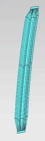
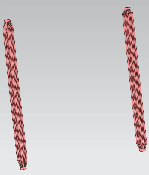
Followed the same procedure of center roof rail for bow roof rail 1 and 2. Length for both rails is 70mm and height is 20mm with master section application. The position of these rails is determined by calculations given below. Using on curve datum plane, the rail positioned with 30% and 60% arc length. Created side flange for spot welding by gap of 0.2mm. (Note: W= 1.71 by calculations)
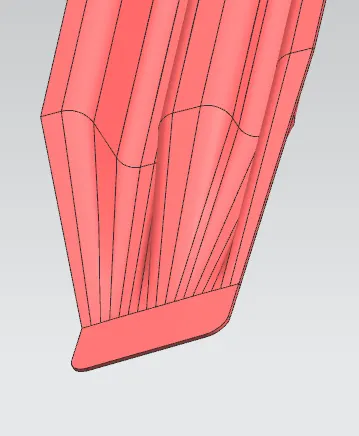
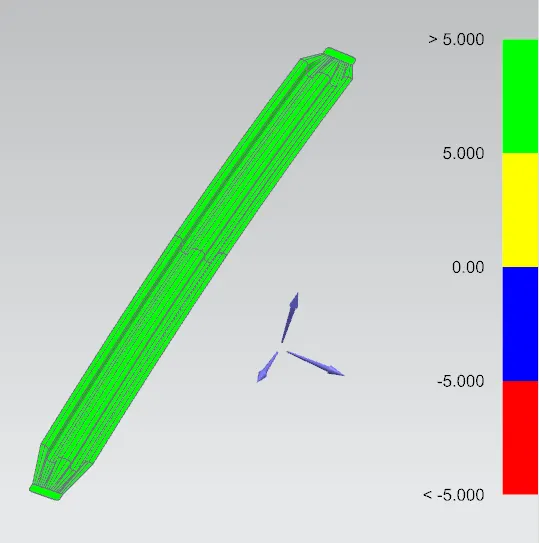
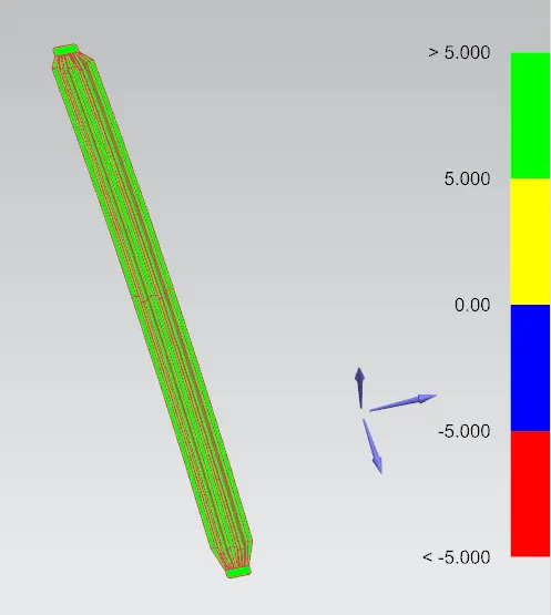
- Draft analysis (Considering draft angle of 5 degree)
1) Outer roof
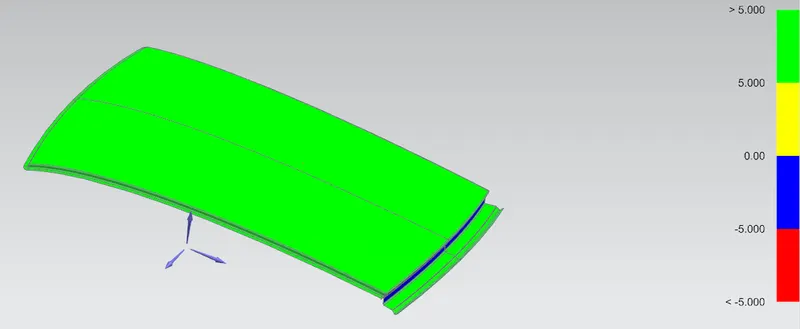
Side core axis required for rear roof rail area.
2) Front roof rail
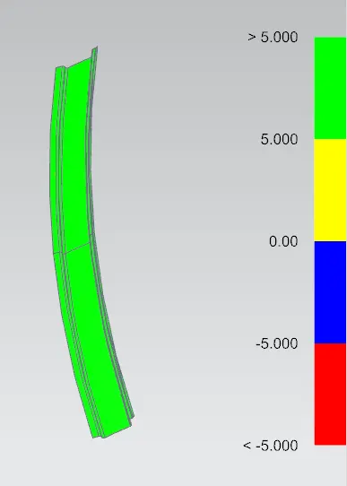
3) Rear roof rail
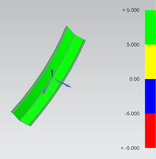
4) Center roof rail
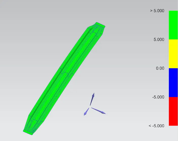
5) Bow roof rail 1&2
- Final Design and assembly