Roof Design
INTRODUCTION:
An automobile roof or car top is the portion of an automobile that sits above the passenger compartment, protecting the vehicle occupants from sun, wind, rain, and other external elements.
When it is seeing from outside of the car, it is just closing the top portion. But in design point of view, it is hard to create the design. Because of you have to create no of support rails for enough strength to withstand the load. 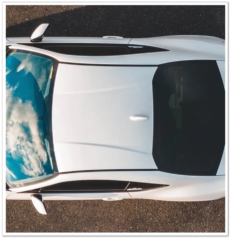
DESIGN CONSIDERATION OF ROOF:
- Visibility criteria
- Head room clearance
- Bow roof position
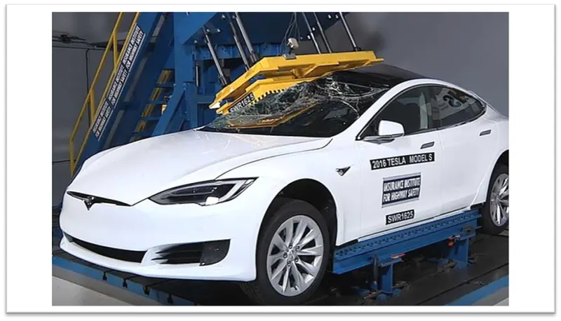
- Heat distortion and Snow load criteriaDraft analysisROOF CRUSH TEST: Roof strength evaluations consist of a quasi-static test conducted on a vehicle’s roof in a manner similar to tests used to judge compliance with Federal Motor Vehicle Safety Standard 216 (Office of the Federal Register, 2009). The main differences between the procedure specified by the Insurance Institute for Highway Safety (IIHS) and that specified by the U.S. federal government are that the IIHS procedure are,CURB WEIGHT MEASUREMENT:
Curb weight values used for calculating the SWR are based on IIHS measurements of a vehicle, not the manufacturer’s specified curb weight.
Vehicle curb weight is measured with full fluid levels using scales manufactured by Longacre Racing Products (Computer scales DX series 72634).
TEST VEHICLE SELECTION:For information on how we select vehicles for our crash test programs, including how we define typically equipped vehicles, see Test Vehicle Selection (IIHS, 2021). Whenever possible, the vehicle acquired for testing is the same vehicle used for the curb weight measurement.
At times, it is necessary to test a vehicle that does not meet the IIHS definition of a typically equipped vehicle, and the curb weight measurement is applied from another vehicle that does meet the definition. In these cases, the test vehicle does not differ from our typically equipped vehicle definition in any way that might influence the roof strength (e.g., a vehicle with a sunroof would not be tested if the typically equipped vehicle lacks this option).
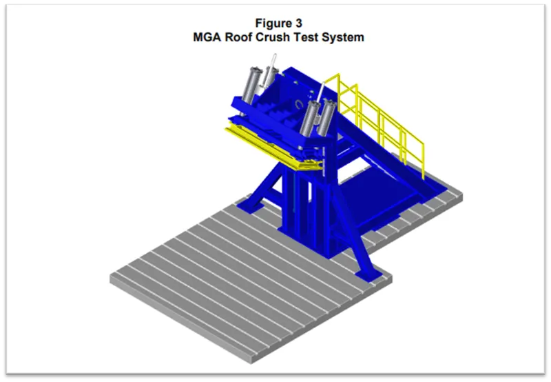
TESTING OF ROOF:Roof strength evaluations are conducted on a quasi-static test system manufactured by MGA Research Corporation (Figure 3).
The system consists of an upright assembly and an attached loading head that can be fixed at varying heights from the ground as well as at pitch angles ranging from −5 to +5 degrees to accommodate testing on the driver or passenger side.
The roll angle is permanently fixed at 25 degrees. Four hydraulic actuators control the movement of the platen along two linear guides. The entire system is mounted on a T-slot bed plate anchored to the floor of the test facility.
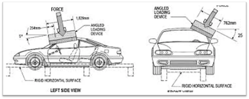
- Two HR A-36 — W10x88 I-beams are mounted on the bed plate perpendicular to the longitudinal axis of the platen. The vehicle, with attached rocker panel support system, is placed on these beams. The vehicle is adjusted so that:
- The longitudinal centerline of platen is within 10 mm of the initial roof contact point.
- The yaw angle of the vehicle relative to the longitudinal axis of the platen is 0 ± 0.5 degrees.
- The midpoint of the platen’s forward edge is 254 ± 10 mm forward of the most forward point of the roof (including windshield trim if it overlaps the roof) lying on the vehicle’s longitudinal centerline.
- CALCULATING THE STRENGTH-TO-WEIGHT RATIO (SWR) RATING
-
Force and displacement data are recorded for 5 seconds prior to each test, while the test system holds the loading platen at initial roof contact.
The data recorded from 1 to 4 seconds of this hold time are averaged for each channel to produce a measurement offset that is subtracted from the data recorded during the crushing of the roof.
After removing the offset for each channel, the force-displacement curve is plotted using the summed output from the five load cells and the average displacement from the four LVDTs. The maximum force prior to 127 mm of platen displacement is divided by the measured curb weight to obtain the SWR.
Both the force and curb weight are rounded to the nearest pound prior to performing the calculation, and the resulting SWR is rounded to the nearest one-hundredth of a unit.
Displacement is rounded to the nearest 0.1 mm. (The maximum displacement where the load can be used for the vehicle rating is 126.9 mm.) The vehicle’s rating is assigned based on the boundaries listed in.
- DESIGN SPECIFICATION FOR THE AUTOMOTIVE ROOF COMPONENT:
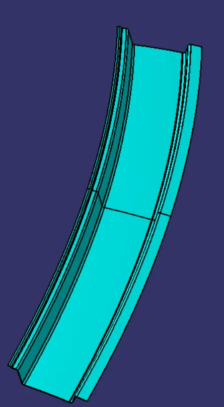
- Front Roof rail:
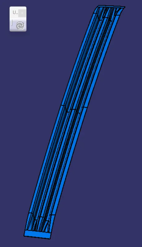
- Bow roof 1:
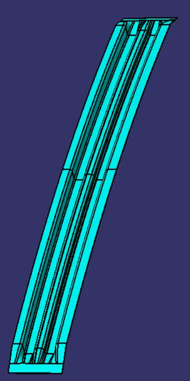
- Centre rail roof:
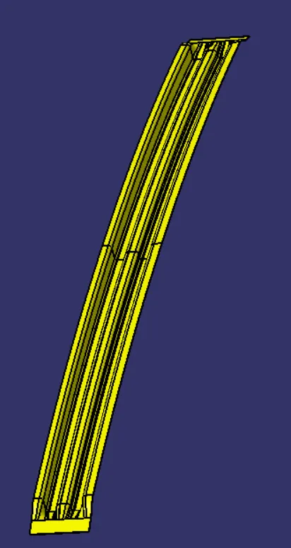
- Bow roof 2:
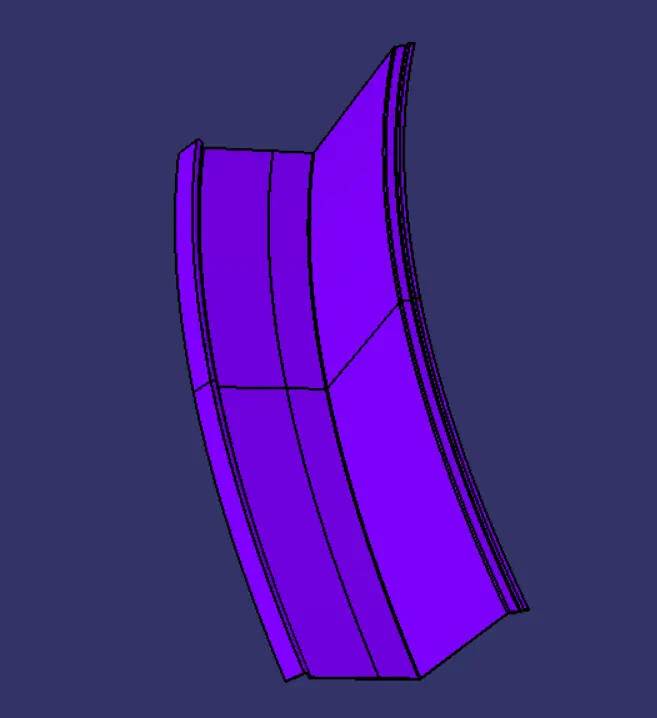 :
: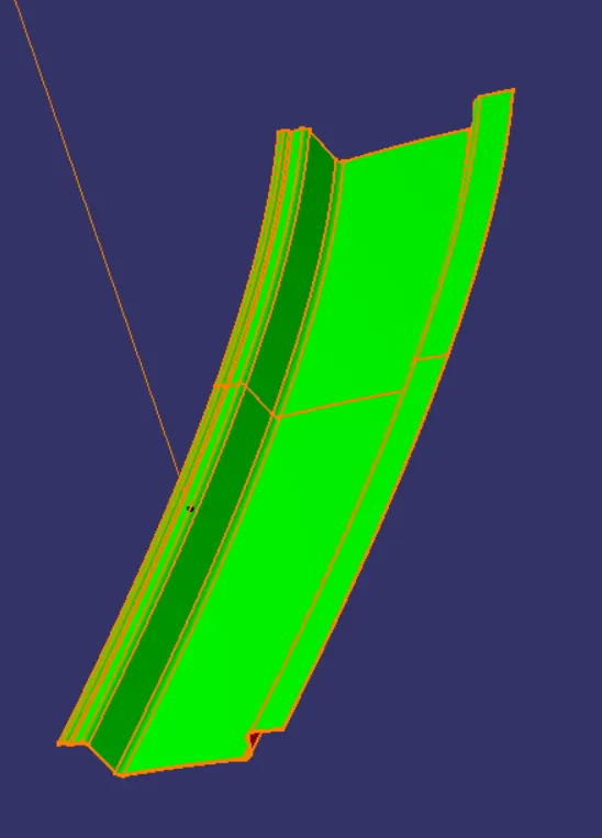
- FRONT ROOF RAIL
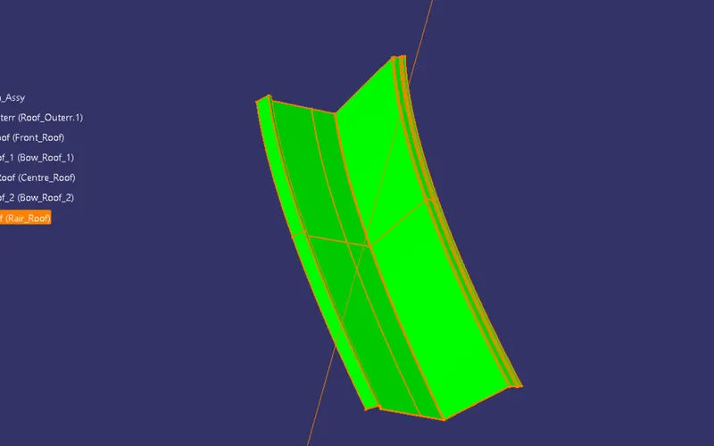
- RAIR ROOF RAIL
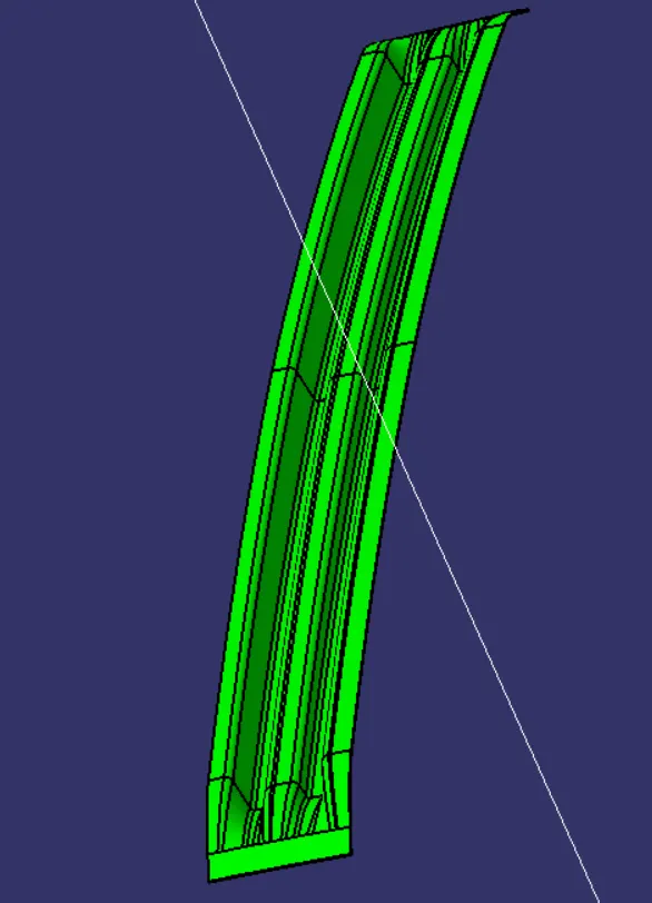
- BOW ROOF RAIL
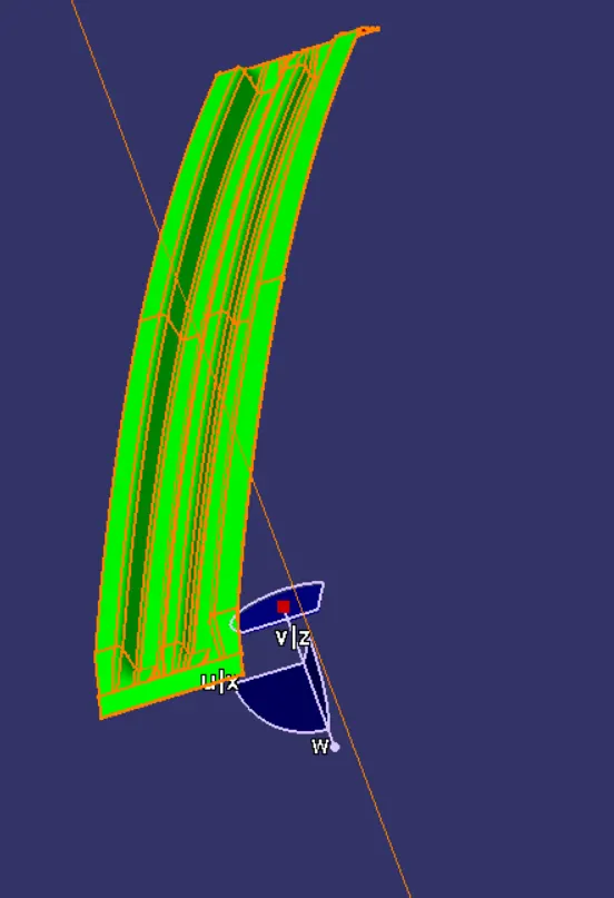
- CENTRE ROOF RAIL
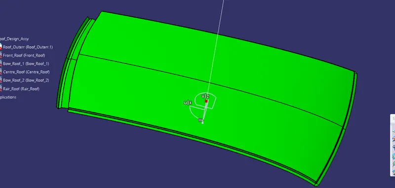
- ROOF OUTER
- Manufacturing technique:Here, The car roof is generally manufactures from the sheet metal sheet. In the manufacturing process the stamping process and at some place bending process is done. Also for joining this all sheets there are mastic sealant is used and at some place the spot welding is done. Here, which portion is visible from the outside is joined using mastic sealant and which portion is hide from outside is joined by spot welding process. Emboss is done by punching which is increase the strength of the panel. also some cutout is done for weight loss.
-
The manufacturing process for car roof parts, comprises the following steps:
By outer board machining process, bar shaped assembly, ring-shaped component processing and roof cant rail processing technology, formed respectively;
Outside plate process: the first step, open straight snips plate: first select applicable cold coiling specification, cold coiling is opened flat; Then according to production material specification, will open cold coiling after flat and be cut into into the iron plate of corresponding size; Finally the iron plate after shear is cleaned to iron filings; The first step, oil pressure, punch press: first iron plate is extended; Secondly to its trimming and punching; Then to its flanging and punching; Finally, after punching completes, it is carried out to the operation of side folding; Completed the making of outside plate;
Bar shaped assembly and ring-shaped component process: the first step, blanking, stamps out iron plate the outline blank of many roof cant rails, a ring-shaped component and a bar shaped assembly; Second step, carries out annular punching to ring-shaped component; Bar shaped assembly and roof cant rail are carried out to bar shaped punching;
- Curvature Study on the Roof:
- Heat Distortion calculation
- Snow Load calculation
-
Heat Distortion:
Heat distortion is temperature limit above which material cannot be used for structural application. This study is useful to find the where the material starts to soften when exposed to a fixed load at elevated temperature. In order to avoid the bending, damage to the roof based on the heat distortion temperature. This study will provide the which position of the bow roof give enough strengthen to roof design.
- Bow–Roof Prediction Formula
-
W = [1.73 x 10^(-3) x L] + [1.85 x 10^(-8) x (R^2)/t] + [ 1.10x10^(-3) x l] - 2.68
Where,
L = Roof Length in X-Direction[mm](Roof dimension in 0-Y)
R = Roof curvature
R = 2(Rx*Ry)/(Rx+Ry)
Rx = X curvature
Ry = Y curvature
t = Roof plate thickness [mm]
l = Bow Roof Span [mm]
Judgment Condition
OK< 2.7
Now from the above equation, for our roof design the parameter is as per below. Here, we have taken the thickness for the sheet for all component is 0.75mm.
So, t = 0.75 mm
Calculating the Heat Distortion criteria:
- To calculate the Heat distortion criteria, we have to take a note of few values and note it down.
- To note down the values, first, we need to create a sketch.
- Create a line at the center of the roof part in the 0-Y axis and then draw another line with a distance of 300mm to the O-Y line.
- Now create lines at a distance of 100mm on both sides to the 300mm line.
- Create a new sketch in which we need to create lines between the bow roofs and rails coming at the center. These lines need to be created in X-direction.
- Using these center line create lines at a distance of 100mm on both sides.
- Now intersect sketch 1 (lines in Y-direction) and sketch 2(lines in X-direction). This result will give us some points where the lines (X & Y)are coinciding with each other.
- Extract the required points and project them on the roof surface. Now using these points create a 3 point arc or circle and note the radius of the arc in the X direction as Rx">RxRx and in the Y direction as Ry">RyRy.
-
Now since we got all the values for calculating the Heat Distortion, substitute these values to the below equation.
W = [1.73 x 10^(-3) x L] + [1.85 x 10^(-8) x (R^2)/t] + [ 1.10x10^(-3) x l] - 2.68
-
case case-nme rx ry l i r t w result 1 fr-bw1 3318.015 14243.49 2035.42 489 5382 0.75 2.0 ok 2 bw1-ctr-r 4054.13 10125.64 2035.42 336 5789 0.75 2.036 ok 3 ctr-r-bw2 4855.36 6591.91 2035.42 336.91 5591 0.75 1.98 ok 4 bw2-rrr 5651 3044.82 2035.42 423 3957 0.75 1.6 ok
-
From the above table we conclude that all the values of W< 2.7. which is fullfill the judgement condition. So, that all bow roofs areas are placed at the right place.
This shows the design is safe in heat distortion criteria.
- Snow Load calculation:
-
Snow load criteria study is used to check the durability of the roof to withstand the snow fall on the roof and regain its original shape without any permanent deformation after load being removed.
Snow Load Prediction Formula
Qr = [Iy x t2] / [α x s x [(Rx + Ry)/2]2 x 10-8]
Where,
α = My x Lx2 x 10-12 , My = Y(Ly-Y)
t = Roof plate thickness [mm]
Ly = Distance between the front and rear roof Rails on the Vehicle along with 0Y[mm]
Length of Roof panel with the center point between Roof rail Front /Rear as the front and rear reference point.
Lx = Distance between the Left and Right end of the roof on the Roof BOW [mm]
The width of the roof panel is exposed on the surface.
Y = Distance front Front Roof Rail to Roof BOW[mm]
s = Distance for which Roof BOW bears divided load [mm]
s = L1/2 + L2/2
Iy = Geometrical moment of inertia of Roof BOW (Y cross-section )[mm4]
Rx = Lateral direction curvature radius of roof panel Y cross-section on Roof BOW [mm]
Roof panel curvature Radius of the Length Lx in Front view
Ry = Longitudinal Direction curvature radius of the Roof panel X cross-section on Roof BOW [mm]
Roof panel X curvature radius of length s in Side view
Judgment condition
Qr ≥ 3.1
250 ≤ s ≤ 380
Now from the above equation, for our roof design the parameter is as per below. Here, we have taken the thickness for the sheet for all component is 0.75mm.
Calculating Snow Load Criteria
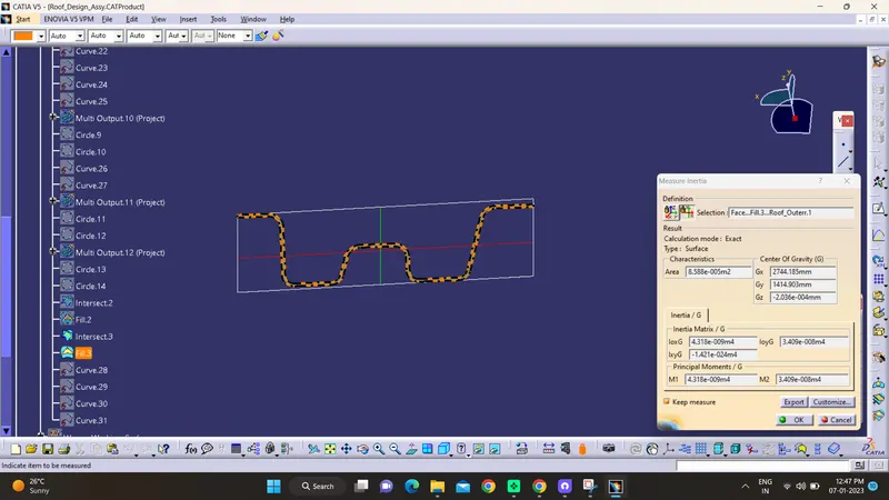
measuring the moment of inertia for the bow roof and center roof we have to take the intersection of the part at the verticle center plane and then projecting this curve on the plane and using inertia analysis we can measure the value, here we have to take the MOI(min) for calculation.
- Bow Roof-1 moment of inertia:
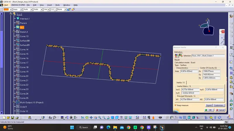
- Center Roof rail moment of inertia:
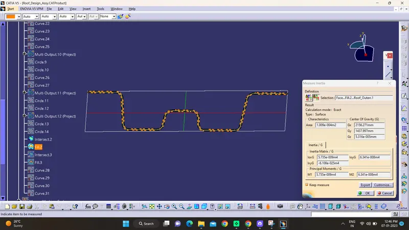
- Bow Roof-2 moment of inertia:
-
RX & RY (X & Y Curvature):
We have to Draw 100mm lines offset to both side of the of 0Y axis line. Now center lines are drawn between each adjacent roof rail respective. and offsetting this center lines to the 100mm both sides. Intersection points are marked on the sketch. Make all the geometry to the reference lines except points. Project the intersection points from the sketch are projected on the roof surface. Join the project points using 3D arc curve and measure the radius value using measurement tools.
For measuring Lx value we have to measure the length of the bow roof rail except the ditch area.
For Ly distance we have to measure the distance between the front roof rail center to the rear roof rail center distance.
For L1 and L2 we have to take the center distance from front roof rail to the bow roof -1 and bow roof -1 to the center roof rail. and respectively do the same for the other roof rail.
For measuring y distance we have to take measurement from center of the front roof rail to the center of the bow roof-1 and same as doing for all.
Now since we got all the values for calculating the Snow Load, substitute these values to the below equation.
Qr = [Iy x t2] / [α x s x [(Rx + Ry)/2]2 x 10-8]
-
Conclusion-
here by seeing the all calculations of the snow load we can see that all our Qr valures are in judgementle conditions only we can see that s values of our calculatiuons are not satisfing the judgementle cond.
so here i just want to rectifyb that the positions of bow roofs and centre roof are need to change according to satisfy the jugementle cond. provided to us .......othe than that everythiung is fine......
cse-nme ly lx y iy t alpa s rx ry my qr
br-1 1937 1061 570 3.96x10³ 0.75 0.879 489 4078 1593 780478 5.19 cr-1 1937 1077 979 4.884x10³ 0.75 0.0011 408.73 4230 10543 938741 7 br-2 1937 1100 1387 1.34x10⁴ 0.75 0.924 484 3765 4107 763791 109