Roof Design
OBJECTIVE: The objective of the challenge is to:
1. Make the all Roof rails accorsding to given master section.
2. Verify wheather the arrangements clears the heat distortion criteria and snow loading criteria or not and suggest if any improvement required accordingly.
3.Perform the draft analysis of each and every component.
Before starting designing any thing engineer should be aware of the purpose of the being made and he should also be aware of the standards, regulation which should be folllowed.
ROOF: Roof of the vehicle is provided to protect the occupant from the outside enviornment more specifically from, sun ,rain , fast passing air, dust and accidents. In order to safe gaurd the occupant from these things the roof has to struggle against the heat so it must pass the HEAT DISTORTION CRITERIA, in colder areas it has to counter the load of snow, so it must follow the SNOW LOADING CRITERIA. Along with these criteria the parts should be anufacturable so it must follow proper draft analysis and draft angle.
There are some additional criteria such as:
1. Front visibility criteria
2.Back visibility criteria
3.Head room clearance criteria
and others as mentioned above;
Lets start check for heat distortion criteria:
Formula-
W = [1.73 x 10^(-3) x L] + [1.85 x 10^(-8) x (R^2)/t] + [ 1.10x10^(-3) x l] - 2.68
Judgement Condition : OK< 2.7
Where,
L = Roof Length in X-Direction[mm](Roof dimension in 0-Y)
R = Roof curvature
R = 2(Rx*Ry)/(Rx+Ry)
Rx = X curvature
Ry = Y curvature
t = Roof plate thickness [mm]
l = Bow Roof Span [mm]
our findings:
| SECTIONS | L | RY | RX | t | I | R | W | STATUS |
| 1 | 2034.2413 | 24625.037 | 2649.4037 | 0.75 | 293.334 | 4784.088 | 1.726463 | PASS |
| 2 | 2034.2413 | 11955.692 | 2908.6316 | 0.75 | 293.334 | 4678.949 | 0.60515 | PASS |
| 3 | 2034.2413 | 14687.187 | 4242.1581 | 0.75 | 259.4303 | 6582.94 | 1.075412 | PASS |
Lets check the Snow loading criteria:
Formula-
Qr =[Iy x t2] / [α x s x [(Rx + Ry)/2]2 x 10-8]
Note: The Qr value given over here is correct. There was a typo error in the formula given in the video.
Where
α = My x Lx2 x 10-12 , My = Y(Ly-Y)
Judgement condition = Qr ≥ 3.1
250 ≤ s ≤ 380
t = Roof plate thickness [mm]
Ly = Distance between the front and rear roof Rails on the Vehicle along with 0Y[mm]
Length of Roof panel with the center point between Roof rail Front /Rear as the reference point of the front and the rear.
Lx= Distance between the Left and Right end of the roof on the Roof BOW [mm]
Width of the roof panel exposed on the surface.
Y = Distance front Front Roof Rail to Roof BOW[mm]
s= Distance for which Roof BOW bears divided load [mm]
s = L1/2 + L2/2
Iy = Geometrical moment of inertia of Roof BOW (Y cross-section )[mm4]
Rx = Lateral direction curvature radius of roof panel Y cross-section on Roof BOW [mm]
Roof panel curvature Radius of the Length Lx in Front view
Ry = Longitudinal Direction curvature radius of the Roof panel X cross-section on Roof BOW [mm]
| section s | LY | Y | MY | LX | alpha | L1 | L2 | S | RX | RY | (RX+RY)/2 | IY | T | QR | status |
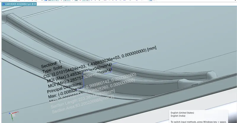
| 1 | 1959.762 | 1202.899 | 910429.5 | 1085.2501 | 1.072275 | 373.333 | 373.333 | 373.333 | 4041.6 | 8829.2579 | 6435.429 | 3285.757 | 0.75 | 11.14809 | pass |
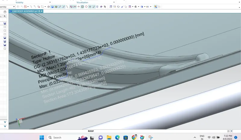
| 2 | 1959.762 | 1576.232 | 604531.8 | 1065.5961 | 0.686443 | 373.333 | 383.5297 | 378.4314 | 4339.791 | 12770.72 | 8555.255 | 7036.167 | 0.75 | 20.81619 | pass |
MOMENT OF INERTIA:
BOW ROOF RAIL 1 :
CENTER ROOF RAIL WITH REINFORCEMENT:
DRAFT ANALYSIS:
MAIN ROOF WITHOUT :
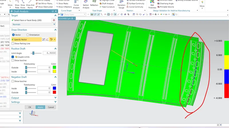
WHOLE ROOF IS CLEARING THE DRAFT ANALYSIS VERY WELL WXCEPT THE REAR DITCH AREA , THE REAR DITCH AREA IS CREATING THE UNDERCUT , THEREFORE SEPERATE OPERATION OTHER THAN MAIN STAMPING WILL BE REQUIRED TO ACHIEVE THE SAME.
FRONT ROOF RAIL:
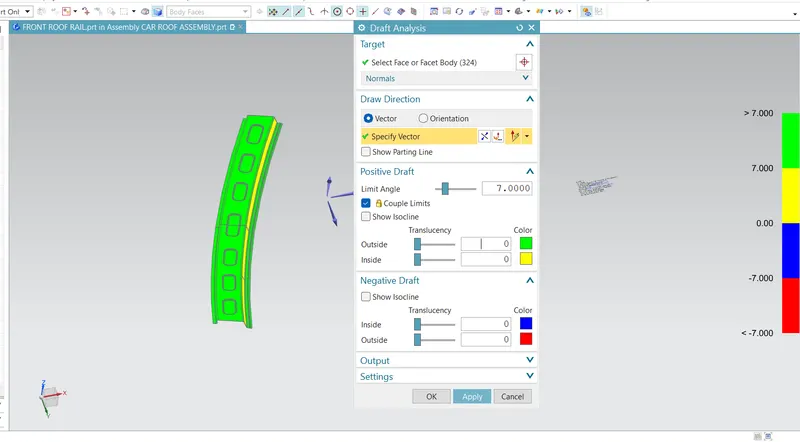
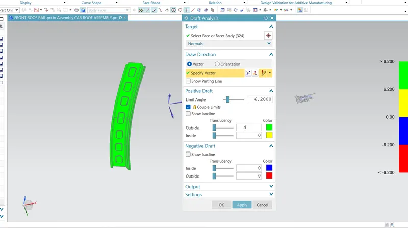
ON COMPARING THE ABOVE TWO FIGURES WE FOUND THAT THERE IS REQUIREMENT OF MORE .8 DEGREE IN THE FRONT ROOF RAIL TO CLEAR THE DRAFT ANALYSIS.
BOW ROOF RAIL 1 :
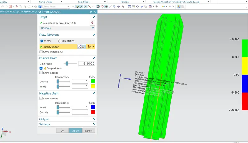
CLEARING THE DRAFT ANALYSIS FROM ALL SIDE.
CENTER ROOF RAIL:
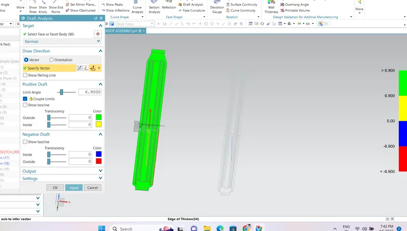
CENTRAL ROOF RAIL IS CLEARING THE DRAFT ANALYSIS .
CENTRAL ROOF RAIL REINFORCEMENT:
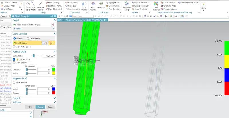
CENTRAL ROOF RAIL REINFORCEMENT IS CLEARING THE DRAFT ANALYSIS .
BOW ROOF RAIL 2:
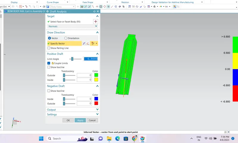
BOW ROOF RAIL 2 IS CLEARING THE DRAFT ANALYSIS .
REAR ROOF RAIL:
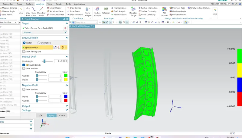
REAR ROOF RAIL IS CLEARING THE DRAFT ANALYSIS .
METHOD OF MANUFACTURING THESE PARTS:
Stamping — also called pressing — involves placing flat sheet metal, in either coil or blank form, into a stamping press. In the press, a tool and die surface form the metal into the desired shape. Punching, blanking, bending, coining, embossing, and flanging are all stamping techniques used to shape the metal.
There are diffrent consideration and best which must be followed to avoid any kind of defects in the resulted parts.those are:
1.HOLE DIA:
When using metal stamping to create holes, the hole diameter should always be equal to or more than 1.2 times the thickness of the material. If the metal has high tensile strength, such as stainless steel alloys, the minimum diameter of the hole should be at least two times wider than the material’s thickness.
D ≥ 1.2T
FOR HIGH TENSILE STRENGTH D ≥ 2T
2. EDGE TO HOLE DISTANCE:
The distance between hole and edge should be a minimum of two stock thicknesses.
3. HOLE TO FORM:
Hole deformation can occur when forming a bend too close to a hole. To prevent this, the spacing should be the bend radius plus 2.5 times the material’s thickness. If the hole’s diameter or width is less than 2.5mm, the distance between the hole and the bend must be a minimum of twice the material’s thickness plus the bend radius. If the hole is more than 2.5mm in width or diameter, the distance should be the bend radius plus 2.5 times the thickness of the material
IF D OR W < 2.5 MM S ≥ R + 2*T
IF D OR W > 2.5 MM S ≥ R + 2.5T
4.SLOT TOFORM:
When bending near long slots, the spacing must be the bend radius plus a minimum of four times the material’s thickness to prevent deformation.
S ≥ R + 4*T
5.NOTCHS AND TABS:
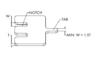 When stamping notches and tabs, the formations should not be less than 1.5 times the thickness of the material. If made smaller, they may experience breakage due to the amount of force exerted on punches.
W ≥ 1.5*T
6. CORNERS:
When forming corners, it’s important to be as generous as possible to facilitate manufacturing. The radius of the punch and die should be at least four times the thickness of the material. Corners can be very sharp if you’re working with a material that is 1.5mm or less in thickness.
R ≥ 4*T
7. SQUARENESS:
Stamping to form a square, 90° angle allows for normal variation of plus or minus 1 degree.
8. FLATNESS:
Flatness should not be over-specified. A component requiring a flatness of fewer than .003 inches may require costly secondary operations.
9. L-SHAPED PARTS:
When stamping L-shaped parts, a bend relief notch should be included to avoid fractures and cracks.
10.Grain Direction
When stamping hard stocks, consider grain direction. To prevent cracking and fractures, the bend line of sharp V-bends should not be parallel to the grain direction. On harder materials, a larger bend radius may also be required to avoid cracking.
11.Burrs
Burrs can be a common occurrence in stamping. When they occur on the outside of a bend, they can create fractures. Burrs can reach heights up to 10% of the material thickness, and they can be removed using various processes. To minimize burr severity, you should avoid complex cutouts and sharp corners when possible. If these can’t be avoided, it’s important to note the burr direction in the design so they can be taken into account during the metal stamping process.
Critical Dimensions
The following are some terminology that are used in sheet metal. Designers need to adhere to machinery guidelines when designing for bending. Bends can be characterised by these parameters. Some critical dimensions that need to be considered when setting up sheet metal in CAD software are sheet metal thickness, the k-factor and bend radius. One needs to check that these factors are consistent with the tooling that will be used in manufacturing. This guide gives important guidelines for good design practice.
Bend line– The straight line on the surface of the sheet, on either side of the bend, that defines he end of the level flange and the start of the bend.
Bend radius – The distance from the bend axis to the inside surface of the material, between the bend lines.
Bend angle – The angle of the bend, measured between the bent flange and its original position, or as the included angle between perpendicular lines drawn from the bend lines.Sometimes specified as the inside bend radius. The outside bend radius is equal to the inside bend radius plus the sheet thickness.
Neutral axis – The location in the sheet that is neither stretched nor compressed, and therefore remains at a constant length.
K-factor – The location of the neutral axis in the material, calculated as the ratio of the distance of the neutral axis T, to the material thickness t. The K-factor is dependent upon several factors (material, bending operation, bend angle, etc.) and is greater than 0.25, but cannot exceed 0.50. K factor = T/t
Bend allowance – The length of the neutral axis between the bend lines or the arc length of the bend. The bend allowance added to the flange lengths is equal to the total flat length.
K-Factor
The K-factor is the ratio between the the neutral axis to the thickness of the material.
Importance of the K-factor in sheet metal design
The K-factor is used to calculate flat patterns because it is related to how much material is stretched during bending. Therefore it is important to have the value correct in CAD software. The value of the K-factor should range between 0 – 0,5. To be more exact the K-factor can be calculated taking the average of 3 samples from bent parts and plugging the measurements of bend allowance, bend angle, material thickness and inner radius into the following formula:
Some basic K-factor values are shown here. Use these as a guideline.
|
Radius
|
Soft / Aluminum
|
Medium / Steel
|
Hard / Stainless Steel
|
|
Air Bending
|
|||
|
0 - t
|
.33
|
.38
|
.40
|
|
t. - 3*t
|
.40
|
.43
|
.45
|
|
3*t. - >3*t.
|
.50
|
.50
|
.50
|
|
Bottom Bending
|
|||
|
0 - t.
|
.42
|
.44
|
.46
|
|
t. - 3*t.
|
.46
|
.47
|
.48
|
|
3*t. - >3*t.
|
.50
|
.50
|
.50
|