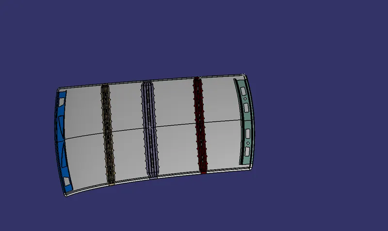
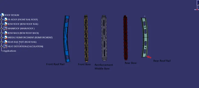
Roof Design
Procedure
AIM:
For the given car roof style, design and build the necessary flanges and reinforcements, including the Ditch area, Frontal Roof rail, Rear Roof rail, Centre Roof rail, and Bow roofs.
Do the roof's curvature study and the calculations for heat distortion and snow load criterion to figure out and explain where the Bow roofs should go.
INTRODUCTION:
A car's roof is the part that sits above the passenger compartment and protects the people inside from the sun, rain, wind, and other outside elements.
Design Procedure:
Bring the file in. File > Open > Browse File > Select the given product (product name.igs) as shown in the figure below:
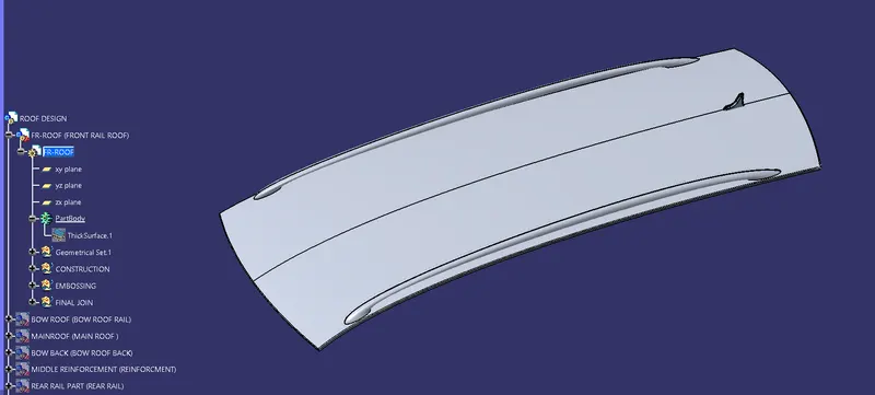
Roof Design
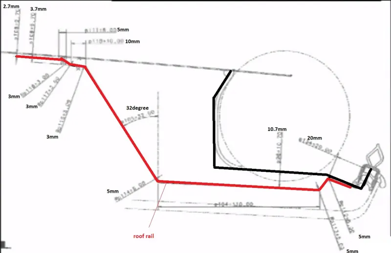
Given surface is A-class, and we have to design Roof surface using this A-class and the master section shown below:
There are two master sections for the front rail roof and one for the back rail roof:
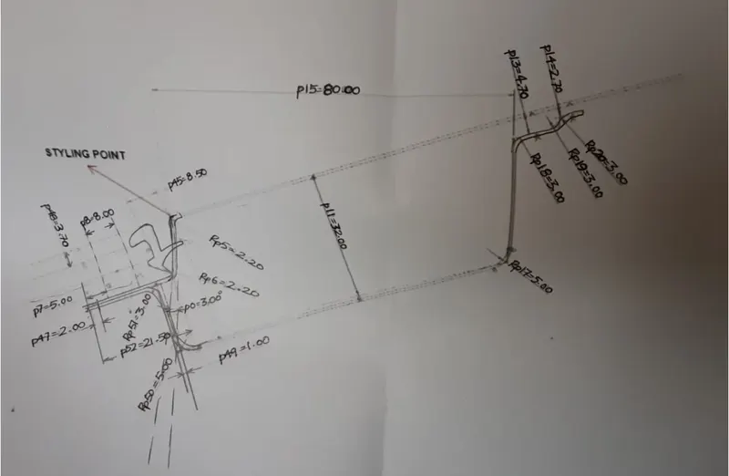
Reinforcements and Design:
The Ditch Area is the part of the main Roof that sticks out and is hidden by other BIW panels. Spot welds are used to connect the roof's rail supports to the Ditch Area. since it is not a surface for styling and stays hidden.
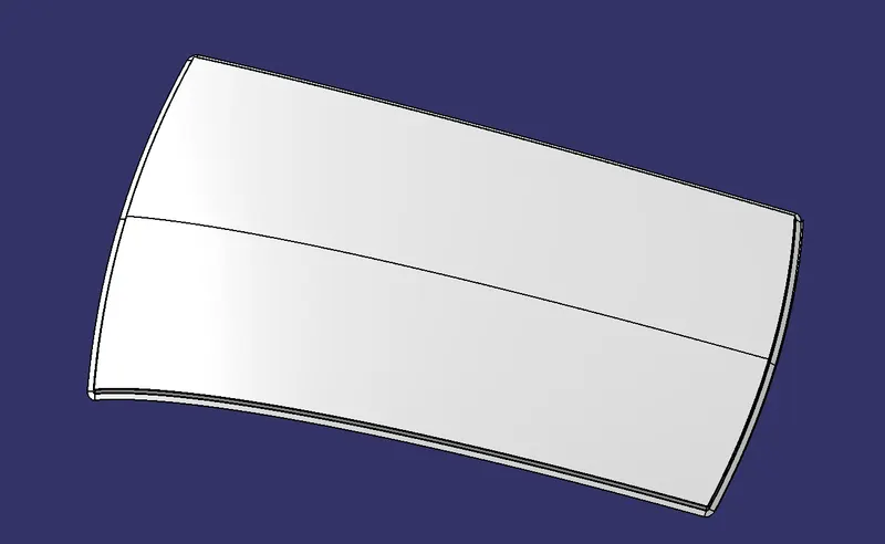
Front Roof Rail:
It's the thing that holds the windscreen glass in place. Body side panels on the outside and inside. Usually, it is 0.75mm thick. The roof surface is cut away from the windscreen end flanges. After taking visibility criteria into account, the bottom-most flanges are chosen. Spot weld is used at the windscreen end, and Mastics sealants are used to join the other end to the roof, which also makes the car stronger.
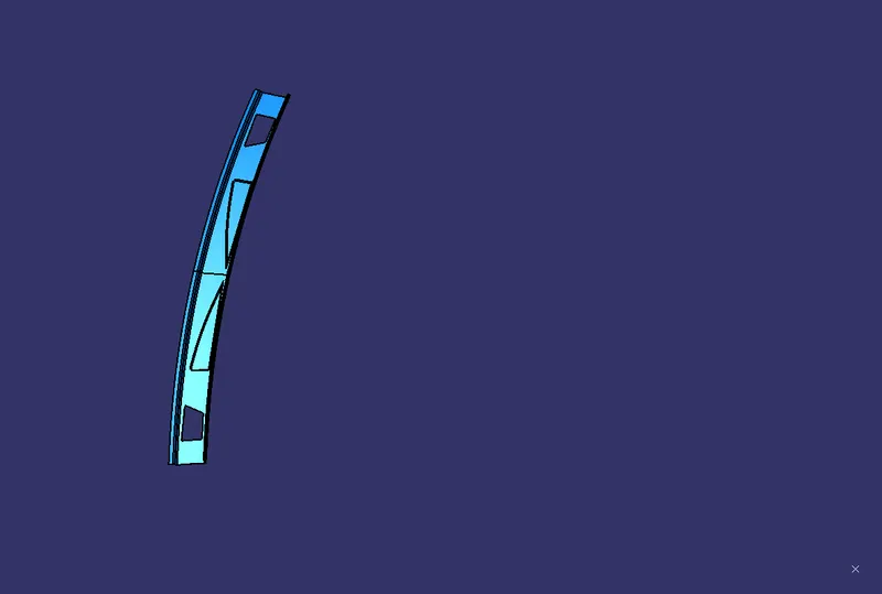
Rear Roof Rail:
It's the support that goes between the back door and the outer and inner panels on the body side. It is usually made from scraps from the outside of the body, so the rail is 0.75mm thick. Like the design of the front roof rails. When designing the rear roof rail from the back door, we had to think about the rear headroom clearance and the rear visibility criteria. We also had to think about the required clearance. At the back door end of the rail, spot welds are used, and Mastic sealants are used to join the other end to the roof.
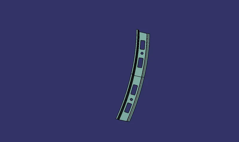
Bow Roof Rails:
When making the centre roof rail and bow roof rail, we have to think about headroom clearance and visibility just like we did with the other design. Here, spot welding is not used to join these roof rails together. Instead, mastic sealants are put in at both ends, since the centre roofs are completely under the roof's surface for looks. Embossing is done to the rails to make them stronger. Different styles have been used with a thickness of 0.75mm to make the material used lighter.
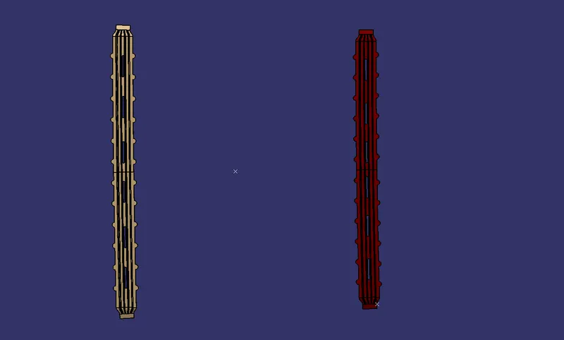
Reinforcement centre rail:
It is the main piece of the roof that holds it up. Their purpose is to provide a place to hook up crossbars and other devices that are used to secure things on the roof of the car. When the car crashes, they absorb energy. It is only 1 mm thick.
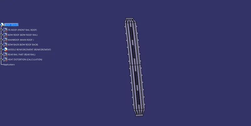
Analysis:
1. CURVATURE STUDY:
It is done to explain why the bow roofs are where they are. There are two main requirements to meet.
Heat distortion criteria
Snow load criteria
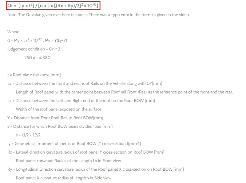
Heat distortion formula :
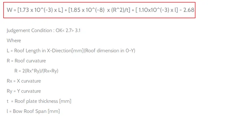
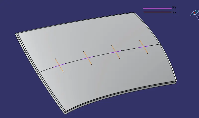
From the model, we can get the figure:
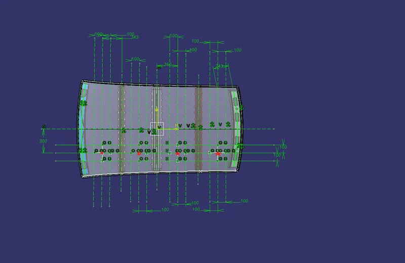
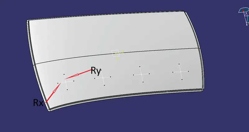
So, when two points on the line meet, we make four points and project them on the roof surface. We then use the spline option to connect these four points.
The line on the left is Rx, and the line on the right is our Ry.
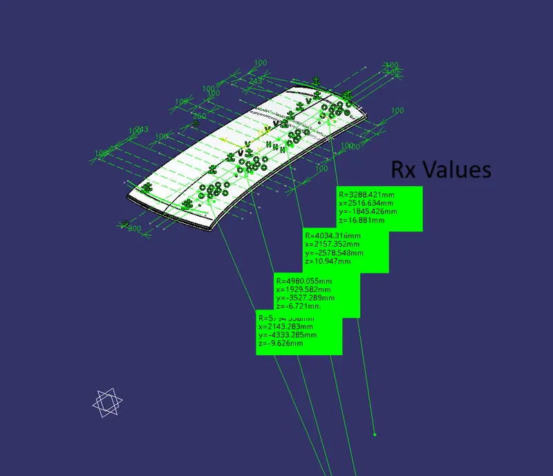
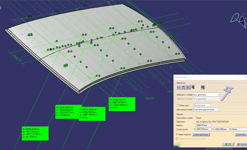
Along the x-axis, the radius of curvature of the bonnet part is given below:
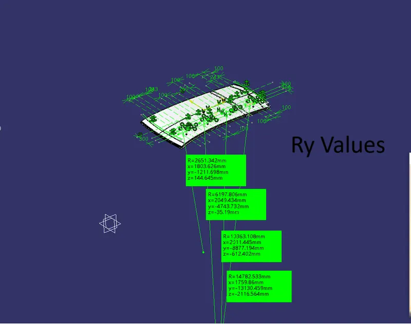
Along the Y-axis, the radius of curvature of the bonnet is given below:
The table below shows the results of the calculations:

Snow Load Criteria:
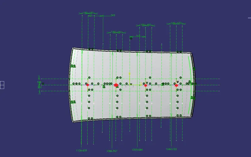
After drawing all the lines, we make points where they meet and then use the spline curve option to project these points on the bonnet. This is what the figure below shows.
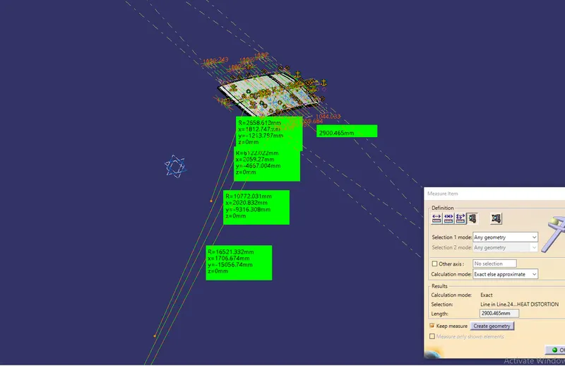
We need a section at each rail for the Geometrical Moment of Inertia, as shown in the figure below:
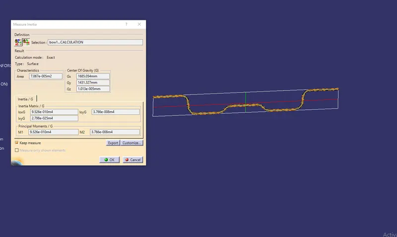
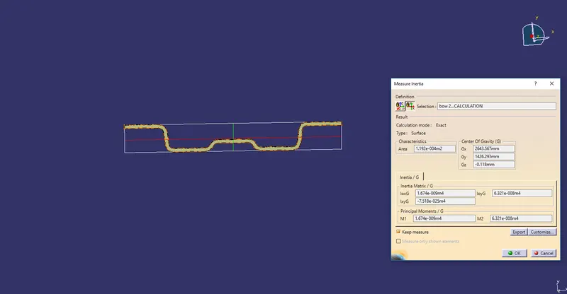
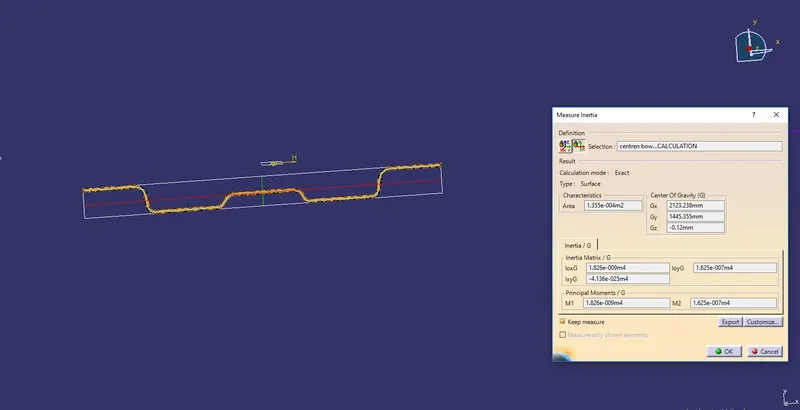
The following table shows the results of the calculations:

Draft Analysis:
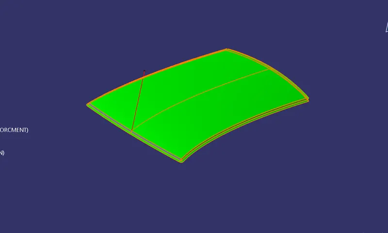
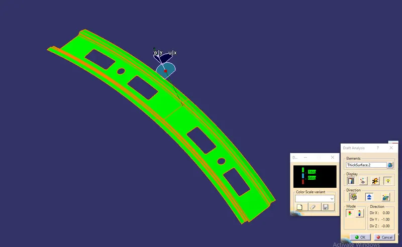
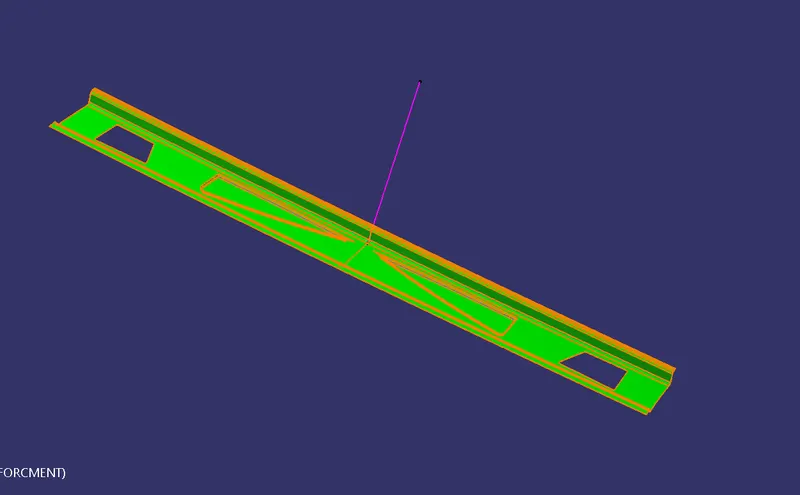
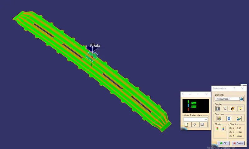
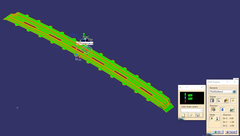
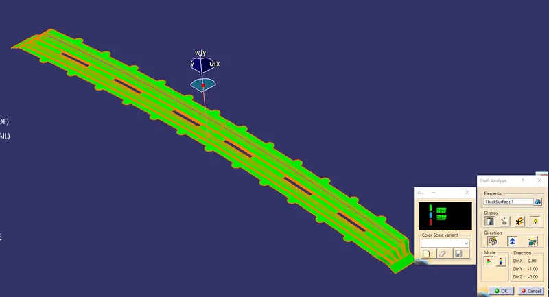
Draft analysis is a way to measure the angle of the draught on different sides of a part in a certain direction. It should be higher than 7 degrees. draught analysing is a command that tells you if your model or design has a draught angle in a certain tool direction.
If the part fits the conditions, it shows up in green. If it doesn't, it shows up in blue or red.
The pictures below show the draught analysis for the Roof, Front Roof Rail, Rear Roof Rail, Bow Roofs, and Reinforcement Center.
Results:
Roof, Front Roof Rail, Rear Roof Rail, Bow Roofs, and Reinforcement Roof Center are all designed by following the Master section with the design parameters for the given class A surface. The final model is shown in Fig. below.