Roof Design
Report of Roof Design
Roof
An automobile roof is considered as an integral part of BIW (body in white) design. A car roof is responsible for protecting the passenger from rain, wind, sunlight, accidents etc. It also offers aerodynamic support to the car when it is in motion. A roof panel assembly includes a roof outer panel/ditch area and inverted hat like reinforcements rails which underlie the outer side edges of the roof outer panel. Roof rails are provided to give strength to the outer panel and also provide support to other commodities present in a car.
There are different rail reinforcements in a roof panel like:
- Front roof rail
- Rear roof rail
- Bow roofs rail
- Reinforcement roof centr
- e
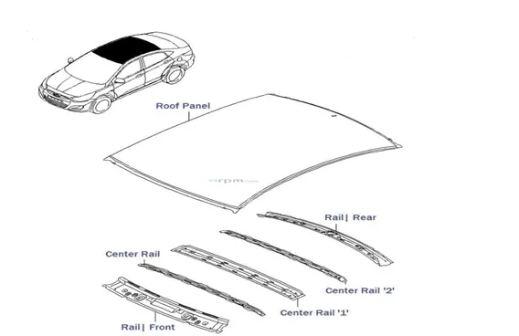
Types of Roof,
There are at least three types of roofs commonly installed on cars, namely
- Sunroofs
- Moon Roofs
- Panoramic roofs.
Objective
- For the given Roof styling and master section, develop the essential flanges and reinforcements, provide appropriate dimension and check for Draft analysis and also submit section inertia analysis report on 0-Y section
- Creation of roof ditch area the tool opening angle is only 3 to 5 degrees.
- Design and develop roof rails as per the given master sections.
- Perform section modulus study for the Master sections created for the Front roof rail, Rear roof rail, Bow Roof Rail and Rear Roof Rail.
- To do a curvature study on the roof and perform calculations to determine the position of the Bow-roofs.
- To perform Heat distortion criteria and Snow Load criteria tests on the designed roof and do optimization if necessary.
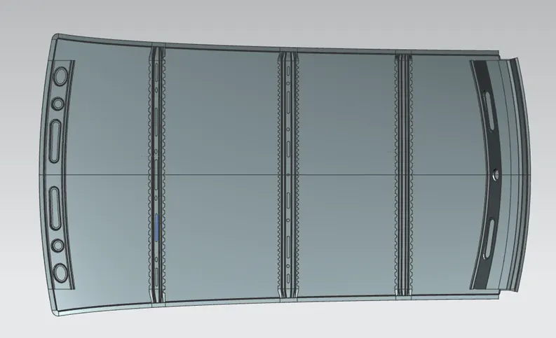
Roof Design
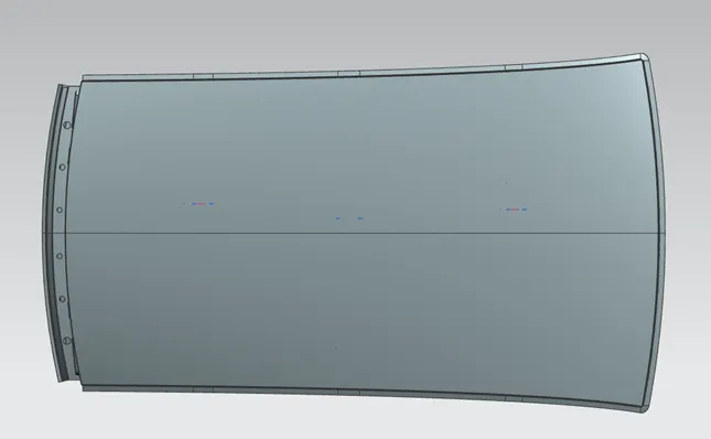
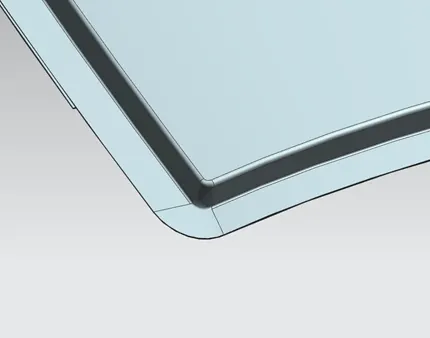
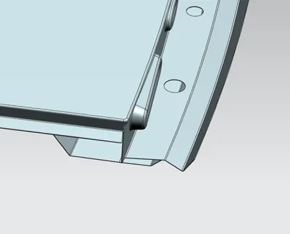
Roof thickness 0.75mm.
Draft angle = 3-7 degrees.
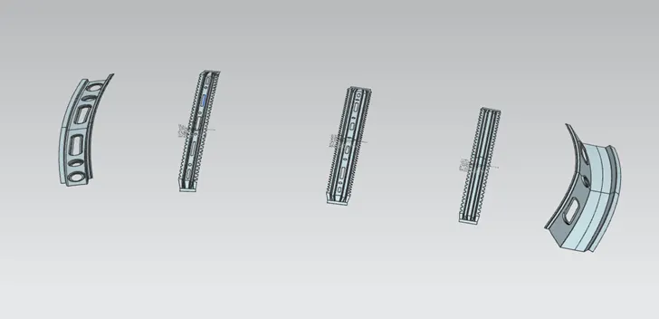
Design of Roof Rails,
Roof Rail id designed as per the master section given for each rail roof,
Roof Rail thickness 0.75mm
Draft angle = 3-7 degrees.
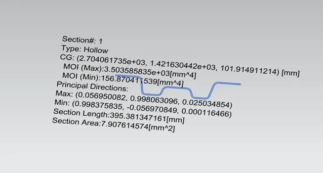
Section Inertia Analysis for Roof Rails,
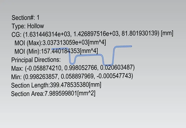
- Bow Rail 1
Min moment of Inertia: 157.44 mm4
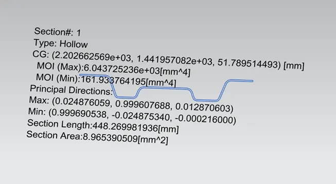
- Centre Rail
Min moment of Inertia: 161.93 mm4
- Bow Rail 2
Min moment of Inertia: 156.87 mm4
Draft Analysis of Roof and Roof Rails
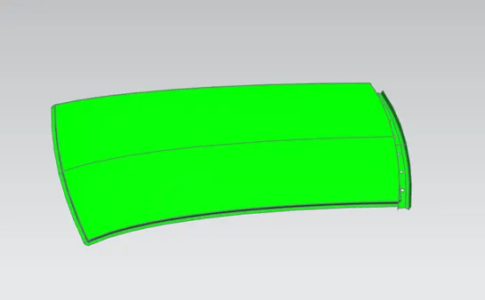
Draft analysis is carried out to obtain visual feedback on back draft condition of the part and an optimum die press direction is defined that maximises back draft. This analysis helps us to avoid die-lock situations, make decisions on an appropriate parting line, obtains suggestions on cutter sizing for machining and other purposes.
- Roof
2.Front Rail
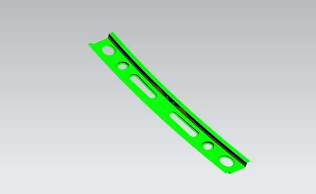
- Bow Rail 1
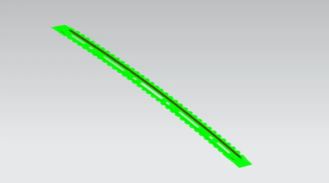
- Centre Rail
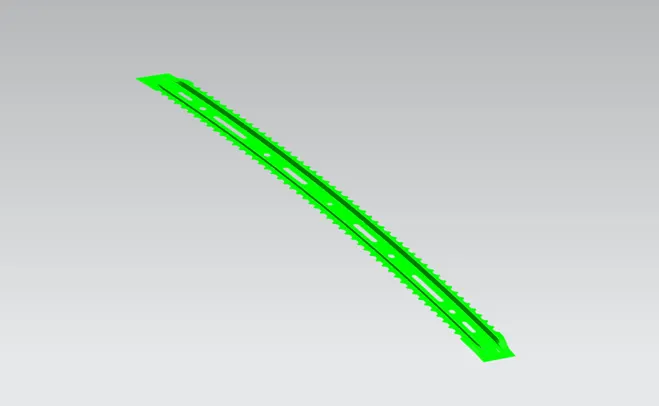
- Bow Rail 2
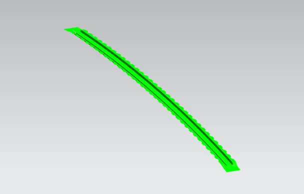
- Rear Rail
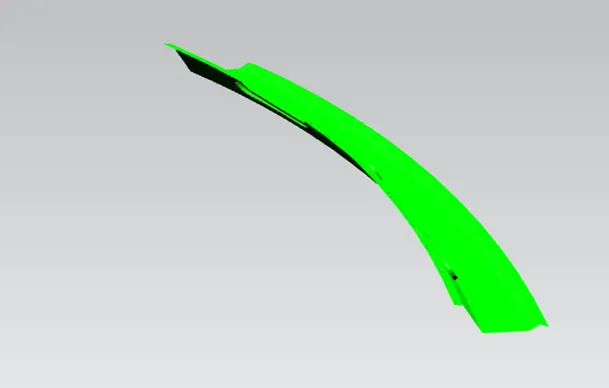
Roof Specifications:
The delivery tests specified for roof assembly are static, dynamic and impact. The purpose of static testing is to verify that roof assembly exhibits no permanent deflection due to distributed load representing snow load and due to heat distortion.
- Heat Distortion Criteria:
Heat distortion test is a type of static load test which plays an important role in maintaining roof strength. Heat distortion temperature is the temperature at which metal softens and deforms under a specified load. From Heat distortion criteria, roof strength can be enhanced by appropriate positioning of bow roof rails.
Bow – roof prediction Formula:
W = (1.73 x 10^-3 x L) + (1.85x10^-8 x (R^2)/t + 1.10 x 10^-3 x l) - 2.68
where,
L = Roof Length in X-Direction [mm] (Roof dimension in 0-Y)
R = Roof curvature = 2(Rx*Ry) / (Rx+Ry)
Rx = X curvature
Ry = Y curvature
t = Roof plate thickness [mm]
l = Bow Roof Span [mm]
Judgement Condition: W < 2.7
|
S.no |
Rails |
Rx |
Ry |
R |
l |
t |
(R^2)/t |
W |
Result |
|
1 |
FR & BR1 |
1348 |
1403 |
1374.95 |
363 |
0.75 |
2520651 |
1.45 |
ok |
|
2 |
BR1& CR |
1875 |
1452 |
1636.61 |
492 |
0.75 |
3571321 |
1.62 |
ok |
|
3 |
CR & BR2 |
2479 |
1445 |
1825.77 |
420 |
0.75 |
4444567 |
1.56 |
ok |
|
4 |
BR2 & RR |
2900 |
1421 |
1907.38 |
321 |
0.75 |
4850811 |
1.45 |
ok |
From above results it can be observed that the designed roof passes Heat Distortion Criteria.
- Snowed Criteria:
The snow load test is a type of static load test used to verify that roof assembly exhibits no permanent deflection due to a distributed load representing snow load: the distributed pressure applied is in the range 10-15 N/dmᶺ2.
Qr = [Iy x t2] / [α x s x [(Rx + Ry)/2]2 x 10-8]
α = My x Lx2 x 10-12 , My = Y(Ly-Y)
Ly = Distance between front and rear roof rails[mm]
Lx = Distance between left and right end roof rails[mm]
Y = Distance between centre of front roof rail to centre of bow roof rail [mm]
S = Distance for which roof bow bears divided load [mm]
Iy = Geometrical moment of inertia of roof Bow (Y cross section) [mm4]
Rx = Lateral direction curvature radius of roof panel Y cross section on roof bow
Ry = Longitudinal direction curvature radius of roof panel X cross section on roof bow
t = Roof plate thickness [mm]
Judgment condition : Qr ≥ 3.1
|
S.no |
Rails |
Y |
Ly |
Lx |
α |
Iy |
t |
s |
Rx |
Ry |
Qr |
Result |
|
1 |
FR & BR1 |
363 |
2133 |
1148 |
0.85 |
157.44 |
0.75 |
427 |
1348 |
1403 |
12.95 |
OK |
|
2 |
BR1& CR |
492 |
2133 |
1089 |
0.96 |
161.93 |
0.75 |
456 |
1875 |
1452 |
7.54 |
OK |
|
3 |
CR & BR2 |
420 |
2133 |
1088 |
0.85 |
156.75 |
0.75 |
370 |
2479 |
1445 |
7.27 |
OK |
|
4 |
BR2 & RR |
321 |
2133 |
0 |
0.75 |
0 |
2900 |
1421 |
From above results it can be observed that the designed roof passes Snowed Criteria.
Conclusion:
Hence the roof rails designed as per the given master section and done the section inertia and draft analysis and calculated the heat distortion and snowed conditions.