Roof Design
Aim:-
For the Given Roof styling, create an ASSEMBLY by developing the essential flanges for the outer roof and creating the reinforcements.
Provide appropriate dimensions and check for Draft analysis.
Do a curvature study on the roof and perform calculations to determine the position of the Bow-roofs.
Suggest and implement remedies in the design if the criterion is not full-filling
Start with the creation of a roof ditch area with a tool opening angle of 7 degrees.
Develop the reinforcements as separate parts
Bow–Roof Prediction Formula
W = [1.73 x 10^(-3) x L] + [1.85 x 10^(-8) x (R^2)/t] + [ 1.10x10^(-3) x l] - 2.68
Where,
L = Roof Length in X-Direction[mm](Roof dimension in 0-Y)
R = Roof curvature
R = 2(Rx*Ry)/(Rx+Ry)
Rx = X curvature
Ry = Y curvature
t = Roof plate thickness [mm]
l = Bow Roof Span [mm]
Judgment Condition
OK< 2.7
Snow Load Prediction Formula
Qr = [Iy x t2] / [α x s x [(Rx + Ry)/2]2 x 10-8]
Note: The Qr value given over here is correct. There was a typo error in the formula given in the video.
Where,
α = My x Lx2 x 10-12 , My = Y(Ly-Y)
t = Roof plate thickness [mm]
Ly = Distance between the front and rear roof Rails on the Vehicle along with 0Y[mm]
Length of Roof panel with the center point between Roof rail Front /Rear as the front and rear reference point.
Lx = Distance between the Left and Right end of the roof on the Roof BOW [mm]
The width of the roof panel is exposed on the surface.
Y = Distance front Front Roof Rail to Roof BOW[mm]
s = Distance for which Roof BOW bears divided load [mm]
s = L1/2 + L2/2
Iy = Geometrical moment of inertia of Roof BOW (Y cross-section )[mm4]
Rx = Lateral direction curvature radius of roof panel Y cross-section on Roof BOW [mm]
Roof panel curvature Radius of the Length Lx in Front view
Ry = Longitudinal Direction curvature radius of the Roof panel X cross-section on Roof BOW [mm]
Roof panel X curvature radius of length s in Side view
Judgment condition
Qr ≥ 3.1
250 ≤ s ≤ 380
Solution:-
Roof in Automobile:
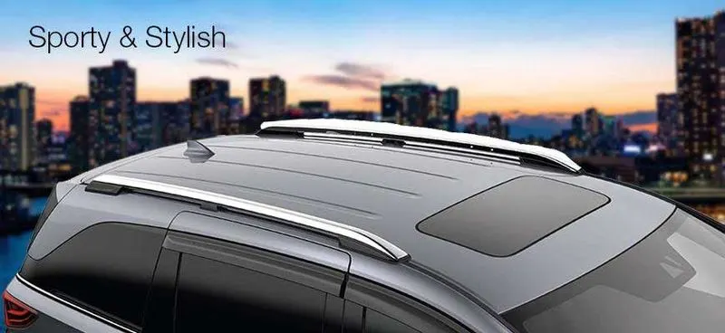
An automobile roof is the portion of an automobile that sits above the passenger compartment, protecting the vehicle occupants from sun, wind, rain, and other external elements.
Roof crush test:
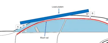
Roof strength evaluations consist of a quasi-static test conducted on a vehicle’s roof in a manner similar to tests used to judge compliance with Federal Motor Vehicle Safety Standard 216 (Office of the Federal Register, 2009). The main differences between the procedure specified by the Insurance Institute for Highway Safety (IIHS) and that specified by the U.S. federal government are that the IIHS procedure are,
- Specifies testing one side of a vehicle’s roof
- Does not include a headroom criterion
- Specifies testing to a given displacement instead of a given force level
- Specifies setting the vehicle’s pitch angle during testing based on the measured on-road pitch angle.
An overall rating is assigned based on the peak strength-to-weight ratio (SWR) measured within 127 mm of plate displacement.
Curb weight measurement:
Curb weight values used for calculating the SWR are based on IIHS measurements of a vehicle, not the manufacturer’s specified curb weight.
Vehicle curb weight is measured with full fluid levels using scales manufactured by Longacre Racing Products (Computer scales DX series 72634).
Test vehicle selection:
For information on how we select vehicles for our crash test programs, including how we define typically equipped vehicles, see Test Vehicle Selection (IIHS, 2021). Whenever possible, the vehicle acquired for testing is the same vehicle used for the curb weight measurement.
At times, it is necessary to test a vehicle that does not meet the IIHS definition of a typically equipped vehicle, and the curb weight measurement is applied from another vehicle that does meet the definition. In these cases, the test vehicle does not differ from our typically equipped vehicle definition in any way that might influence the roof strength (e.g., a vehicle with a sunroof would not be tested if the typically equipped vehicle lacks this option).
Once the test vehicle has been acquired, either the driver or passenger side of the vehicle is selected for testing. For most vehicles, the test side is chosen at random. However, for roof designs that appear asymmetrical, engineering judgment is used to select the side of the roof that may result in a lower peak force.
Test vehicle preparation:
With the vehicle on a level surface, the on-road pitch angle at the front door sill is measured on both sides of the vehicle. Unless the vehicle manufacturer requests otherwise, roof racks and other nonstructural items that may be contacted during the test are left as installed from the factory.
Any trim or other components are removed if they interfere with supporting the vehicle along its rocker panels. For vehicles with vertical pinch weld flanges on the bottom of the rocker panels, the vehicle support system consists of one I-beam (HR A-36 W4X13) for each rocker panel.
Each I-beam has a clamping system incorporated on the top that is tightened against the pinch weld flange to clamp the system in place (Figures 1 and 2). When the pinch weld flange has a bend that prevents supporting the sill with one I-beam, more than one I-beam can be used on each side of the vehicle.
For vehicles with no pinch weld flange, or with a nonvertical flange angle that precludes clamping, mounting by another method may be necessary, such as that described in the National Highway Traffic Safety Administration’s Laboratory Test Procedure (2006).
Prior to testing, the front-row seat back on the side being tested is reclined to prevent interaction with the crushing roof. Rear seats are latched in their upright position. All windows are closed and doors are locked.
Procedure of roof design:
Roof assembly the conditioner task of the roof panel is the top component shielding passenger production at connection of the body sites front and roof cross members in case of rollover component integrity is provided by the compartment frame while the roof target is only to avoid the injection of passenger providing protection against hard local contact and it’s also with stand snow load and heat distortion and also protecting wind passages. The roof is decent bye aerodynamics to pay Passing through the wind direction.
Design considerations of roof :
- Visibility criteria
- Head room clearance
- Bow roof position
- Heat distortion and Snow load criteria
- Draft analysis
Outer roof :
First we need to do the outer roof rail,
- Now download the given roof raw part
- open NX software to do the assembly of roof
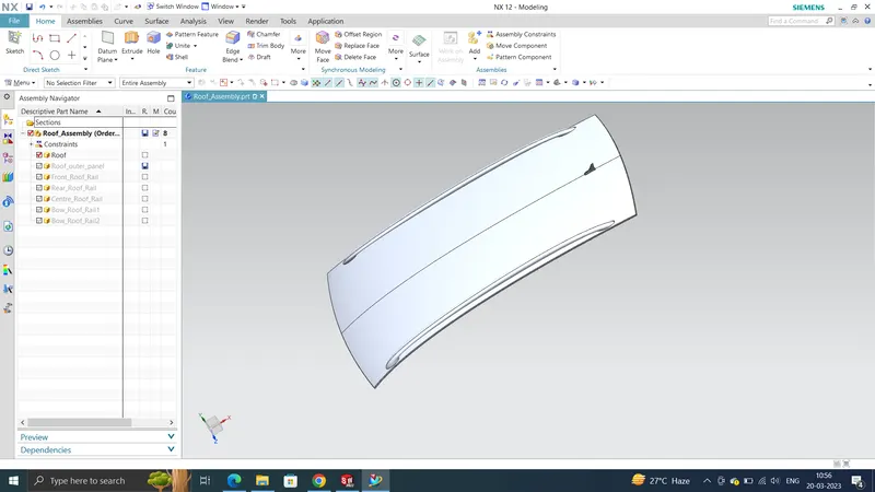
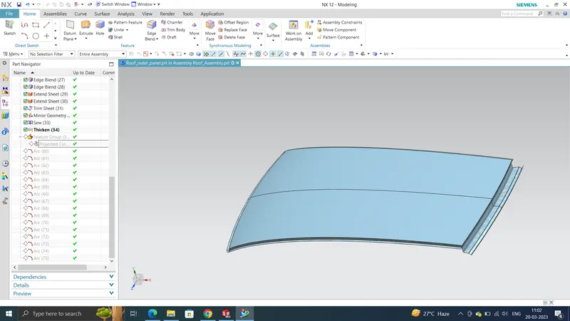
We can design the Roof, front roof rail, rear roof rail, bow roof, center reinforcement rails are creating with help of styling surface for roof.
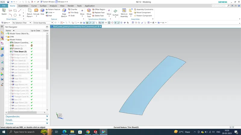
by using master section designed the outer roof
Front roof rail:
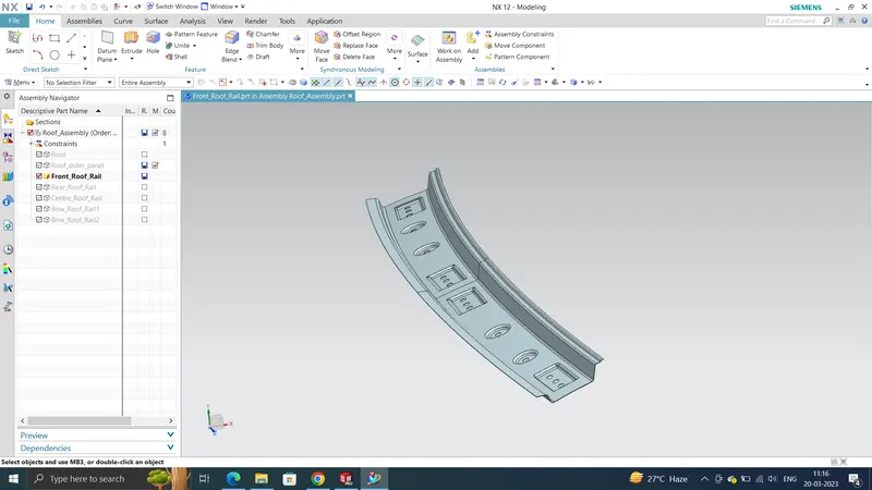
now we need to do the front roof rail, hear is master section of the front roof rail,
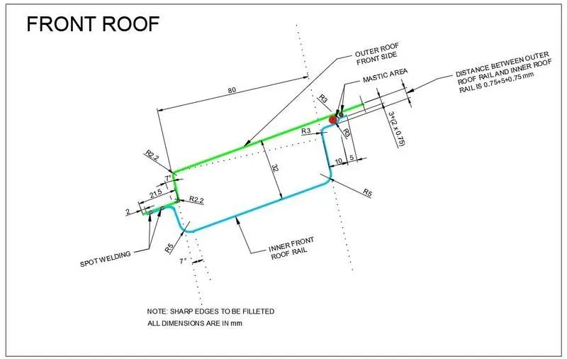
- Use the Command Wave Geometry linker and select the extracted roof and the dich area part
- Now Offset the surface to 32mm and dich area to 1.5mm(For Spot Welding)
- Use Law extension command for dich area to create the lower part of the front roof area
- Extend and attach the offsetted sheet till it touches the law extended sheet
- Trim and extend the sheet and lawextended sheet
- Then use Offset curve in face command and select the lower edge and set it to 80mm and trim the unwanted sheet
- Use law extension to bulid the lower side for the other part at an angle of 25deg
- Now offset the surface for 5+0.75+0.75mm for the mastic points for the first curve the trim and extend
- Then use offset curve in face and set it for 10mm
- Then offset the surface again for 3+0.75+0.75 for the mastic points for the second curve and use trim and extend
- Then use offset curve in face and set it for 5mm
- Now Fillet the edges to 3.75+t thickness
- Now Draw some Sketches and create embosses
- Then Extend the sheet and trim the sheet so that there is no gap after mirroring
- Now Mirror the sheet and sew it
- Thciken it for 0.75mm
Rear Roof Rail:
- First Create the Part file for the Rear roof rail in assembly file.
- Following the master section which is given to us as input, we will be creating the Rear Roof Rail.
Master section of the Rear Roof Rail
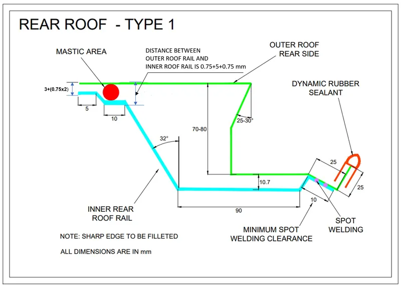
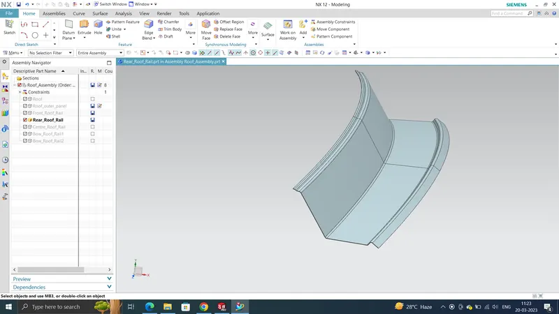
Rear Roof rail is also the reinforcement for the outer panel and it joins the backdoor and the body side outer. For designing the Rear roof rail also, we have developed a master section based on the functional requirements which are Rear visibility criteria, Rear head room clearance, Tool opening and mastic clearance. See the below image of Rear Roof rail design.
Similar operations which were performed in the Front Roof Rail needs to be followed to create the Rear Roof Rail.
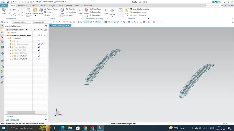
Bow Roof Rail 1 and 2:
- First Create the Part file for the Front Bow roof rail.
- Following the master section which is given to us as input, we will be creating the Bow Roof Rail.
Master section of Bow Roof
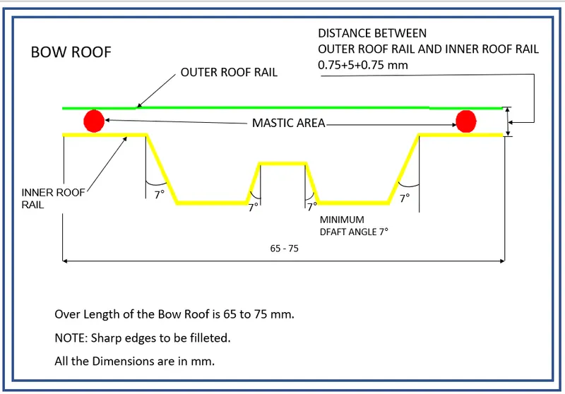
A reinforcement is created to provide additional strength to the area where the roof surface is flat.
- Use the Command Wave Geometry linker and select the extracted roof and the dich area part
- Use a datum plane on the curve at 33% and 75%
- Use Intersection curve command then select the face and the dataum plane the intersection line will be created
- Then offset curve in face
- Trim sheet by selecting the curves
- Use law extenstion command and join the sheets at 7deg
- Blend the edges with edge blend command
- Now offset the dich are to 1.5mm in downward direction
- Now use bridgecommand and sketch a curve which can be use as a guide
- Now use Through Curve mesh command to join these surface
- Now create an Sketch for mastic points
- Now Draw some Sketches and create embosses
- Then Extend the sheet and trim the sheet so that there is no gap after mirroring
- Now Mirror the sheet and sew it
- Thciken it for 0.75mm
Center Roof Rail:
- First Create the Part file for the Front roof rail.
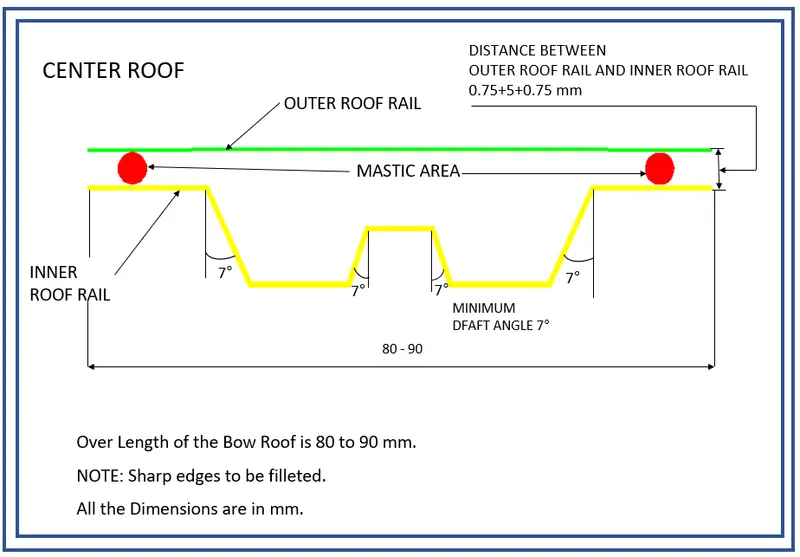
- Following the master section which is given to us as input, we will be creating the Center Roof Rail.
Master section of Center Reinforcement Rail
- Use the Command Wave Geometry linker and select the extracted roof and the dich area part
- Use a datum plane on the curve at 50%
- Use Intersection curve command then select the face and the dataum plane the intersection line will be created
- Then offset curve in face
- Trim sheet by selecting the curves
- Use law extenstion command and join the sheets at 7deg
- Blend the edges with edge blend command
- Now offset the dich are to 1.5mm in downward direction
- Now use bridgecommand and sketch a curve which can be use as a guide
- Now use Through Curve mesh command to join these surface
- Now create an Sketch for mastic points
- Now Draw some Sketches and create embosses
- Then Extend the sheet and trim the sheet so that there is no gap after mirroring
- Now Mirror the sheet and sew it
- Thciken it for 0.75mm
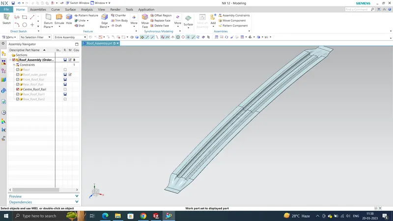
Roof has been desinged by considering all the parameters and considerations:
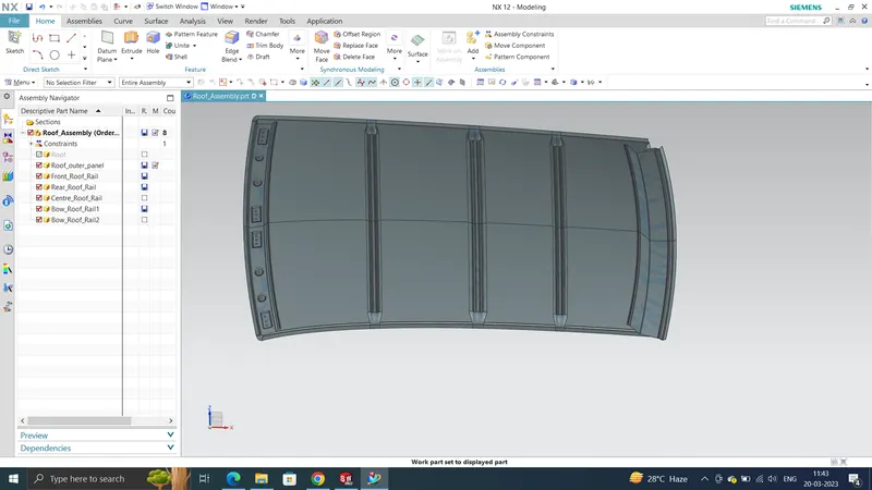
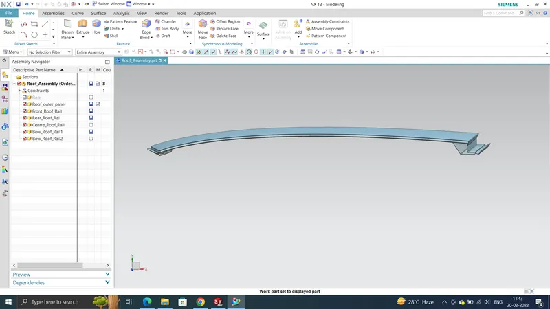
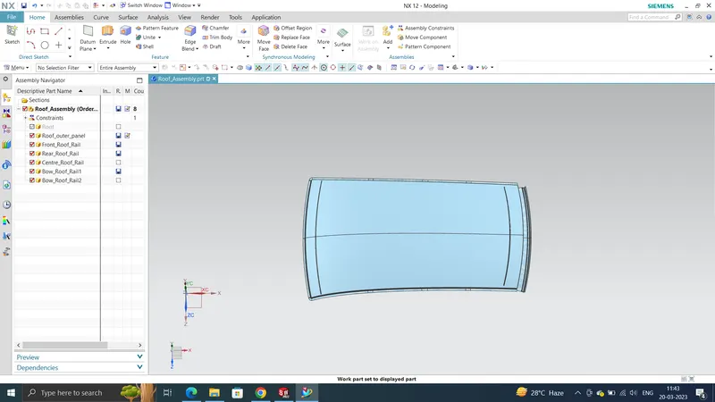
Calculation:
In the assembly we’re going to calculate heat distortion criteria and snow load criteria. Heat distribution criteria is the calculation of how the roof will stand the heat capacity. And also measure the draft analysis after roof assembly. In snow load criteria we’re going to calculate snow load with stand capacity of roof. In the foreign countries in the rainy season there is a snowfall in that kind of situation roof must withstand the snow load that is why we calculate this
Heat Distortion Criteria: Predicting heat distortion for the roof is important since it is exposed to the heat for a long time and high temperature will affect the roof structure if the designing does not confirm with the heat distortion criteria. the study helps to determine the position of roof to provide strength to the route to avoid bending and deflection of the roof due to heat. bow curvature study you see following formula will help best check whether the boardroom potion important required strength of roof.
Bow–Roof Prediction Formula(Heat Distortion Formula)
W = [1.73 x 10^(-3) x L] + [1.85 x 10^(-8) x (R^2)/t] + [ 1.10x10^(-3) x l] - 2.68
Where,
L = Roof Length in X-Direction[mm](Roof dimension in 0-Y)
R = Roof curvature
R = 2(Rx*Ry)/(Rx+Ry)
Rx = X curvature
Ry = Y curvature
t = Roof plate thickness [mm]
l = Bow Roof Span [mm]
Judgment Condition
OK< 2.7
Calculating the Heat Distortion criteria:
- To calculate the Heat distortion criteria, we have to take a note of few values and note it down.
- To note down the values, first, we need to create a sketch.
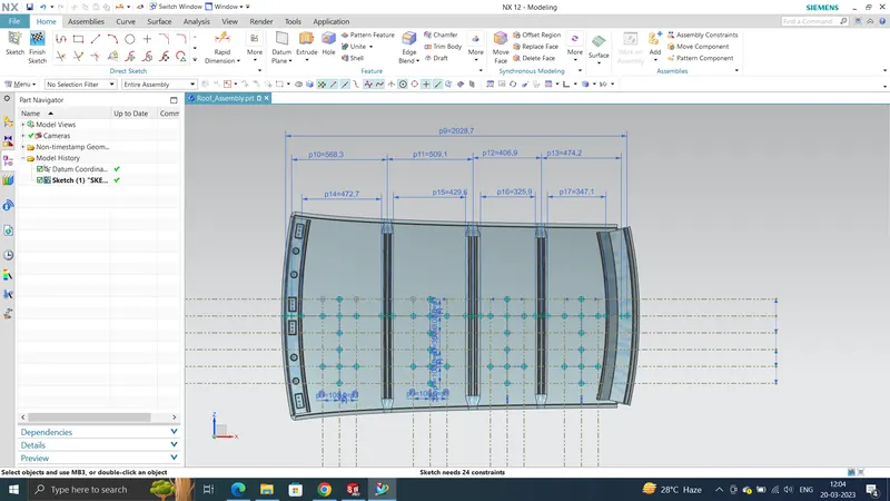
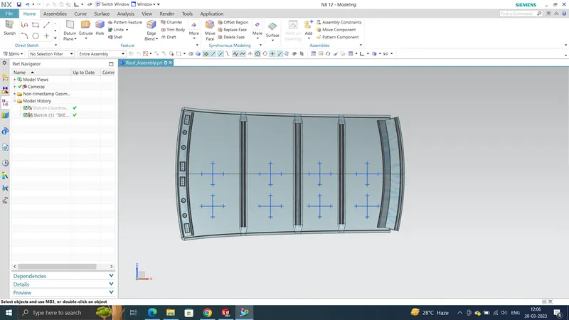
- Create a line at the center of the roof part in the 0-Y axis and then draw another line with a distance of 300mm to the O-Y line.
- Now create lines at a distance of 100mm on both sides to the 300mm line.
- Create a new sketch in which we need to Project the Roof Rails curves lines between the bow roofs and rails coming at the Edge. These lines need to be created in X-direction.
- Using these Edge line create lines at a distance of 100mm on both sides.
- Now To find Rx and Ry we have to take the intersection points and meassure them
- so project the points on the surface and use Arc/Circle Command to meassure the curvature
- Now since we got all the values for calculating the Heat Distortion, substitute these values to the below equation.
| HEAT DESTORTION | |||||||||||
| S.NO | Roof rails | Rx | Ry | Rx*Ry | Rx+Ry | R = 2(Rx*Ry)/(Rx+Ry) | L | t | l | W | Result |
| 1 | FRR-BOW1 | 2776.85 | 5721.1 | 15886636.54 | 8497.95 | 3738.933869 | 2028.7 | 0.75 | 472.7 | 1.6943 | OK |
| 2 | BOW1-CRR | 7052.28 | 4758.62 | 33559120.65 | 11810.9 | 5682.737243 | 2028.7 | 0.75 | 429.6 | 2.0986 | OK |
| 3 | CRR-BOW2 | 10980.81 | 3898.85 | 42812531.07 | 14879.66 | 5754.503943 | 2028.7 | 0.75 | 325.9 | 2.0048 | OK |
| 4 | BOW2-RRR | 14806.16 | 3246.26 | 48064644.96 | 18052.42 | 5325.008499 | 2028.7 | 0.75 | 347.1 | 1.9108 | OK |
Conclusion:
As per the standard acting load were w < 2.7. In that case above the diagram are all pass the requirement of the manufacturing standard.
Snow Load Prediction Formula
Qr = [Iy x t2] / [α x s x [(Rx + Ry)/2]2 x 10-8]
Note: The Qr value given over here is correct. There was a typo error in the formula given in the video.
Where,
α = My x Lx2 x 10-12 , My = Y(Ly-Y)
t = Roof plate thickness [mm]
Ly = Distance between the front and rear roof Rails on the Vehicle along with 0Y[mm]
Length of Roof panel with the center point between Roof rail Front /Rear as the front and rear reference point.
Lx = Distance between the Left and Right end of the roof on the Roof BOW [mm]
The width of the roof panel is exposed on the surface.
Y = Distance front Front Roof Rail to Roof BOW[mm]
s = Distance for which Roof BOW bears divided load [mm]
s = L1/2 + L2/2
Iy = Geometrical moment of inertia of Roof BOW (Y cross-section )[mm4]
Rx = Lateral direction curvature radius of roof panel Y cross-section on Roof BOW [mm]
Roof panel curvature Radius of the Length Lx in Front view
Ry = Longitudinal Direction curvature radius of the Roof panel X cross-section on Roof BOW [mm]
Roof panel X curvature radius of length s in Side view
Judgment condition
Qr ≥ 3.1
250 ≤ s ≤ 380
Calculating the Snow Load Criteria:
- To calculate the Snow Load Criteria, we have to take a note of few values and note it down.
- To note down the values, first, we need to create a sketch.
- Create a line at the center of the roof part in the 0-Y axis.
- Now using this O-Y line as a center create lines with a distance of 100 on both sides.
- Create a new sketch in which we need to create lines between the bow roofs and rails coming at the center. These lines need to be created in X-direction.
- Using these center line create lines at a distance of 100mm on both sides.
- Now intersect sketch 1 (lines in Y-direction) and sketch 2(lines in X-direction). This result will give us some points where the lines (X & Y)are coinciding with each other.
- Extract the required points and project them on the roof surface. Now using these points create a 3 point arc or circle and note the radius of the arc in the X direction as Rx">Rx and in the Y direction as Ry">Ry.
- Now since we got all the values for calculating the Snow Load Criteria, substitute these values to the below equation.
- Qr=Iy×t2α×s×[Rx+Ry2]2×10⁻⁸">Qr=Iy×t2α×s×[Rx+Ry2]2×10⁻⁸
Calculating the Section Modulus:
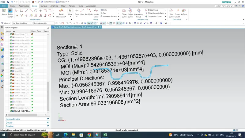
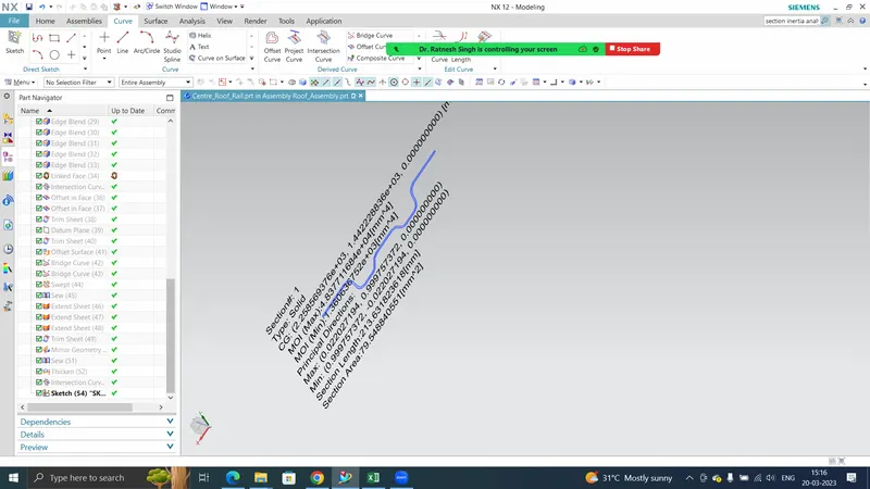
To calculate the section modulus, we need to take the intersection of all the components individually on the 0-Y section.
Bow roof 1:
Center roof:
Bow Roof 2:
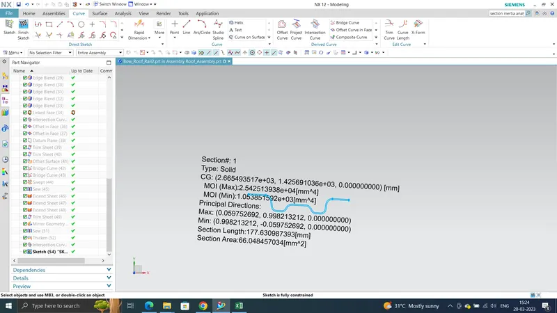

Note: For the Bow Roof 2 - Rear Roof Rail there will be no snow load criteria since the L2 is not available in that region.
Conclusion:
As per the standard acting load were Qr >= 3.1. In that case above the diagram are all pass the requirement of the manufacturing standard.
Draft analysis:
Draft analysis is the command enable you to detect if the part you draft will be easily removed. This type of analysis performs based on colour rains identification zones on the analysis element where the deviation from draft direction at any point corresponding to the specific value. This value is from both negative from positive direction. When the negative value represents good rating and positive value more than 5 will be risk high. That represent the smoothness of the part. In parts smoother more good design. In our design we going to perform this analysis to roof, front rail, rear rail, bow rails and centre rail. And check whether the roof is smoother and less in rating
Outer Roof Panel:
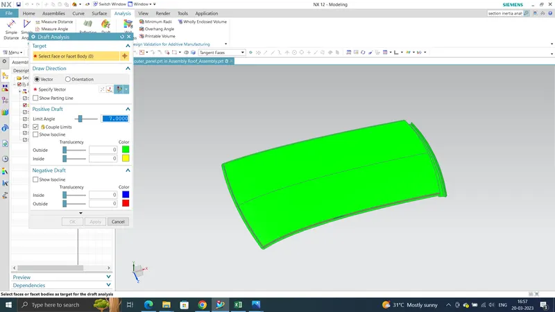
Front Roof Rail:
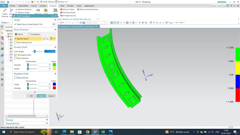
Bow Roof 1:
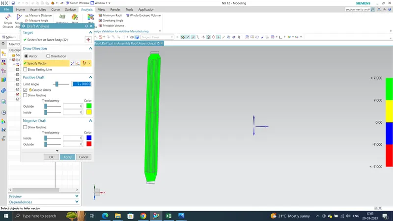
Center Roof Rail:
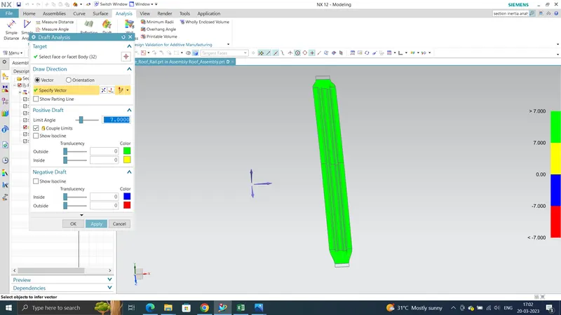
Bow Roof 2:
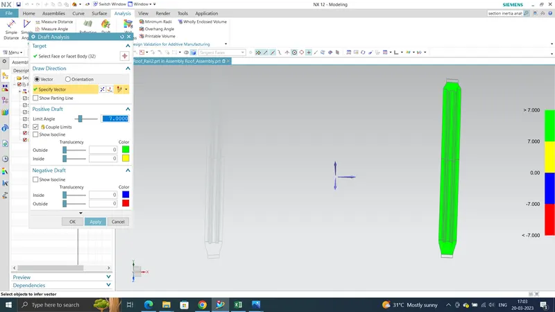
Rear Roof Rail:
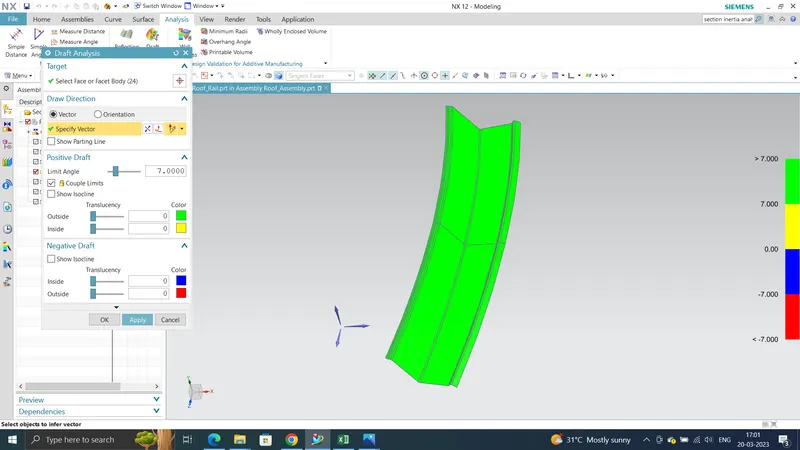
RESULTS:
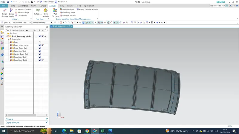
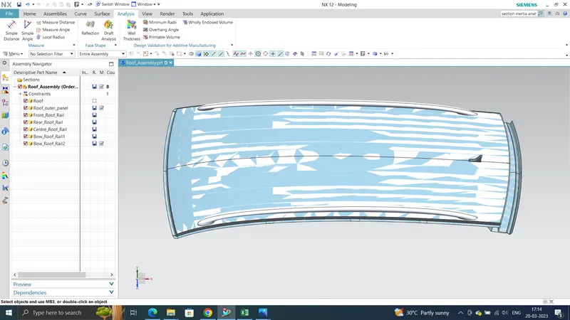
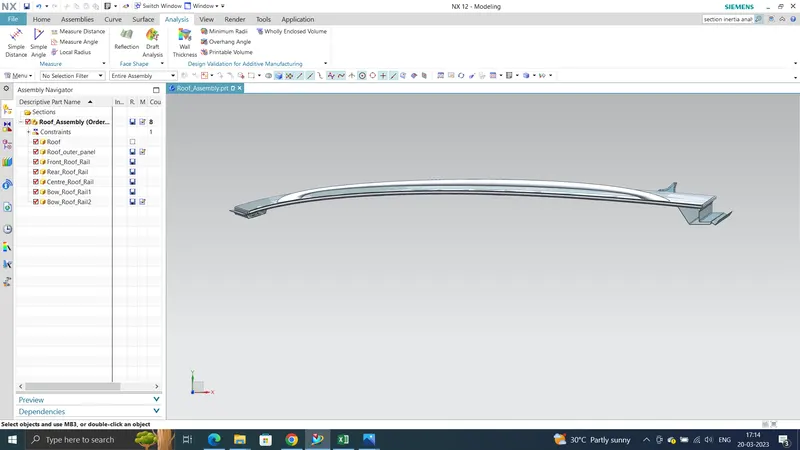
The Roof of a car has been successfully developed with all the required components and a draft analysis have also been performed for the same.
Final Roof Modal:
CONCLUSION:
Hence finally the roof design and analysis of the snow load and heat distortion complete. In the heat distortion calculated and part are pass the industry standard. In the snow load calculation are done and there is only one part not pass the stand. This project was done by NX CAD software