Roof Design
Roof Design:-
- An automobile roof is the portion of an automobile that sits above the passenger compartment, protecting the vehicle occupants from sun, wind, rain, and other external elements. Under the styling surface that is seen from the outside, many other structures under the roof contribute to its strength and stability. The number of such reinforcement structures/supports differs concerning the size of the vehicle. They are primarily installed on flatter areas of the roof to enhance strength.
- A roof of a car consists a outer skin panel which is designed with aesthetics and aerodynamics in mind and the support structure of the panel. In case of passenger cars the roof is designed to be flexible enough to regain its original shape after smaller loads due to snow of light impacts are applied to it. At the same time the roof needs to withstand all the impact forces and self weight in a roll over incident. Hence the support structure is a vital part of the roof design. Usually it consists of a Front roof rail, a rear roof rail, roof reinforcement, and 1 or more bow rails.
- The front and rear roof rails are used to join the roof with the rest of the BIW of the car along with front windshield, dampening components, sealants etc. Roof reinforcement panel is provided where the roof is flatter usually in the middle along the length of the car again to provide strength to the roof.
- Bow roof rails are provided as and when necessary, and are attached to the roof panel using mastic sealants. The longer the roof, more the number of bow rails. The dimensions of the support structure like the depth and length which will affect the front and rear visibility, interior design and material required, headroom and overall space it will occupy is governed by ergonomics and region specific regulations where the car is to be sold.
Roof Crush Test:-
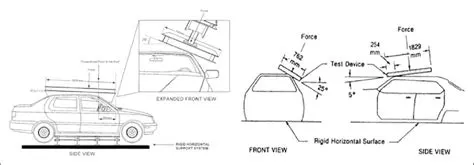
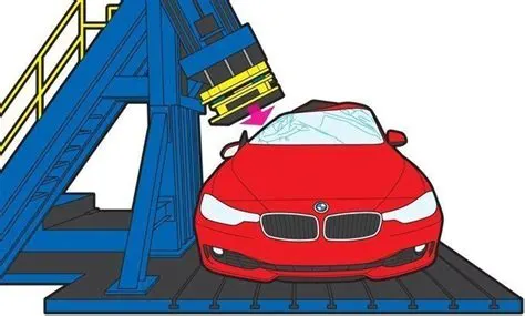
- Test Roof crush is the failure and displacement of an automobile roof into the passenger compartment during a rollover accident. The relationship between injury levels and intrusion or roof crush has been statistically established, but the mechanism has been thought sometimes to be somewhat obscure.
- Safety point of view vehicle roof plays a very crucial role, especially in rollover kind of accidents, in which the vehicle tips over onto its side of the roof. And vehicle rollover crashes are the cause of many fatalities and head, neck, and spine trauma around the world.
Car Rollover Test:-
-
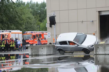
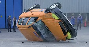
A rollover happens when there is a dramatic effect on the vehicle balance after vehicle traverses a curve which eventually shifts the vehicle center of gravity to one side. Each car’s reliability including the strength of the vehicle pillars holding the roof is determined in every rollover test.
- Vehicle rollovers are divided into two categories: tripped and untripped. Tripped rollovers are caused by forces from an external object, such as a curb or a collision with another vehicle. Untripped crashes are the result of steering input, speed, and friction with the ground.
Design consideration of Roof:-
- Visibility Criteria.
- Head Clearance.
- Curvature Study.
- Heat Distortion and Snow Load Criteria.
- Draft Analysis.
- Safety Parameters.
Thickness and manufacturing requirements:-
- Thickness of Roof panel: 0.75mm
- Reinforcement Thickness = 0.75mm
- Tool opening angle 3 degree
- Emboss depth should not exceed 6mm.
- Minimum filet radius should be more than the 3+thickness
- No sharp corners inside the component
Roof Outer Panel:-
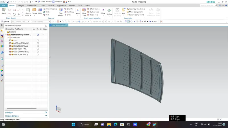
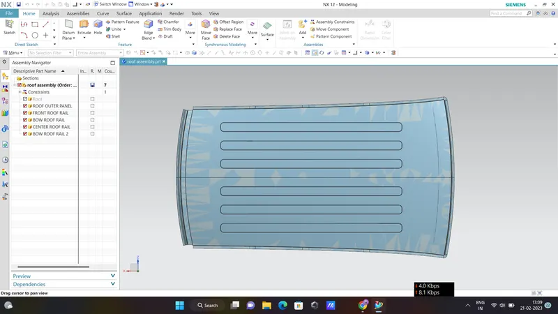
By taking the input styling surface of roof panel then first created the flanges or the ditch area at the four sides with the required open angle of 3 degree. At the front end of the roof panel we have given the flange length of 21.5mm to provide the enough clearance for the windshield and its associated components like rubber sealant. The rear end also created the flanges with the required length and opening angle to allow the joining for the backdoor .Additional beads created on the top of roof panel to increase the strength of the panel.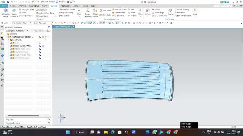
Front Roof Rail:-
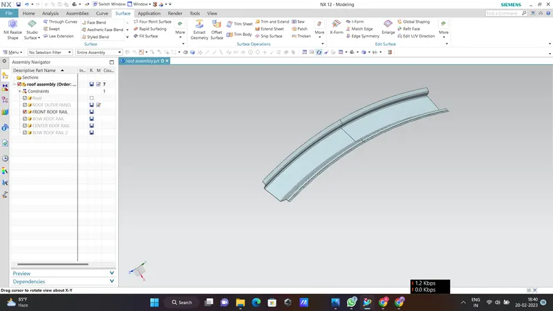
Front Roof rail is the reinforcement for the roof outer panel and as well as it joins the Roof panel with the Windshield glass and body side panel and also supports the bracket map lamp and room lamp mounting. Front roof rail created based on the master section which is developed with above mentioned functional requirements of tool opening angle, required clearance for to join with the windshield glass, visibility criteria, the deepness based on the head room clearances and the clearance mastic joining. See the below master section used for the Front Roof Rail and the Front roof rail design based on the master section.
Rear Roof Rail:-
Rear Roof rail is also the reinforcement for the outer panel and it joins the backdoor and the body side outer. For designing the Rear roof rail also we have developed a master section based on the functional requirements which are Rear visibility criteria, Rear head room clearance, Tool opening and mastic clearance. See the below image of Rear Roof rail design.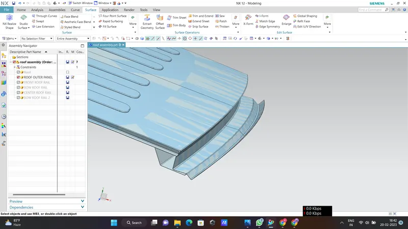
Bow Roof Rails at Centre, Front and Rear:-
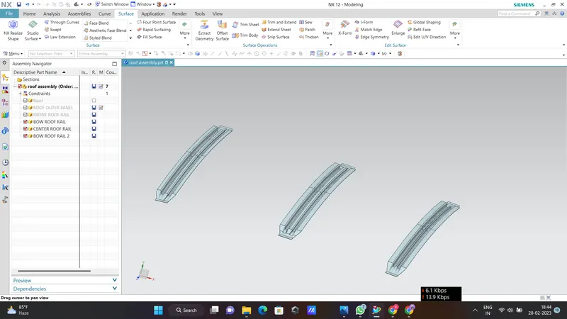
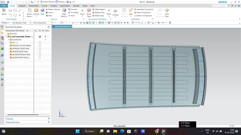
Bow Roof Rails are also the reinforcements of outer panel and are used to strengthen the roof panel and these joins to the Roof panel with the help of mastic sealant to the roof panel and connects to the body side using the spot welding technique. These are designed based on the developed master sections developed using the criteria of Visibility and the head room clearance. And the position of these Bow roofs are mostly recommend to place at the flat portions of the Roof outer panel.
Roof Design with all the Roof rails:-
Analysis of the Roof:-
Heat Distortion Criteria:- The heat distortion study plays an important role in sheet metal usage. Heat distortion temperature is a temperature limit above which the material cannot be used for structural applications. This study is used to predict the heat distortion temperature at where the material starts to soften when exposed to a fixed load at an elevated temperature. To avoid bending or damage on the roof, based on heat distortion temperature, this study will predict the bow roof position on the roof to strengthen the roof.
Bow–Roof Prediction Formula
W = [1.73 x 10^(-3) x L] + [1.85 x 10^(-8) x (R^2)/t] + [ 1.10x10^(-3) x l] - 2.68
Where,
L = Roof Length in X-Direction[mm](Roof dimension in 0-Y)
R = Roof curvature
R = 2(Rx*Ry)/(Rx+Ry)
Rx = X curvature
Ry = Y curvature
t = Roof plate thickness [mm]
l = Bow Roof Span [mm]
Table and Calculations are Performed :-
| ROOF RAILS | L(mm) | T(mm) | Rx(mm) | Ry(mm) | R(mm) | I(mm) | W(mm) | RESULT |
| FRR-BOWR1 | 2029.242 | 0.75 | 5692.127 | 3011.473 | 3938.98 | 516.433 | 1.781 | OK |
| BOWR1-CRR | 2029.242 | 0.75 | 4723.554 | 7194.358 | 5702.83 | 393.585 | 2.065 | OK |
| CRR-BOW R2 | 2029.242 | 0.75 | 3895.38 | 10998.807 | 5753.19 | 333.103 | 2.013 | OK |
| BOW R2-RRR | 2029.242 | 0.75 | 3287.407 | 14533.98 | 5361.99 | 342.676 | 1.916 | OK |
From the above table, it can be concluded that all values of W< 2.7 and also not W>3.1 so thus infer that the current positioning of the Bow roof is good in the state as per the design and found OK.
Snow Load Criteria:-Snow load criteria study is done to check the durability of the roof to withstand snowfall and reflex back to its original shape without any permanent deformation once the load is removed.
Snow Load Prediction Formula:-
Qr = [Iy x t2] / [α x s x [(Rx + Ry)/2]2 x 10-8]
Note: The Qr value given over here is correct. There was a typo error in the formula given in the video.
Where,
α = My x Lx2 x 10-12 , My = Y(Ly-Y)
t = Roof plate thickness [mm]
Ly = Distance between the front and rear roof Rails on the Vehicle along with 0Y[mm]
Length of Roof panel with the center point between Roof rail Front /Rear as the front and rear reference point.
Lx = Distance between the Left and Right end of the roof on the Roof BOW [mm]
The width of the roof panel is exposed on the surface.
Y = Distance front Front Roof Rail to Roof BOW[mm]
s = Distance for which Roof BOW bears divided load [mm]
s = L1/2 + L2/2
Iy = Geometrical moment of inertia of Roof BOW (Y cross-section )[mm4]
Rx = Lateral direction curvature radius of roof panel Y cross-section on Roof BOW [mm]
Roof panel curvature Radius of the Length Lx in Front view
Ry = Longitudinal Direction curvature radius of the Roof panel X cross-section on Roof BOW [mm]
Roof panel X curvature radius of length s in Side view
Table and Calculations are Performed :-
| ROOF RAILS | L(mm) | T(mm) | Rx(mm) | Ry(mm) | L1(mm) | L2(mm) | S(mm) | α(mm) | I(mm) | QR(mm) | RESULT |
| FRR-BOW R1 | 1963.430 | 0.75 | 4271.06 | 3024.01 | 617.101 | 468.515 | 542.808 | 1.046 | 185.3 | 13.7 | OK |
| BOW R1-CRR | 1963.430 | 0.75 | 7163.92 | 3834.85 | 468.515 | 408.065 | 438.29 | 1.108 | 209.2 | 8.01 | OK |
| CRR-BOW R2 | 1963.430 | 0.75 | 4307.85 | 11600.38 | 408.065 | 490.51 | 408.065 | 0.793 | 211.7 | 5.28 | OK |
It is observed from the values that obtained values of QR> 3.1.As per the above results the Roof design is satisfied the Snow load criteria.
Conclusion:-Thus completed the Roof Design of car with respect to all design and functional considerations. The current design satisfied the draft analysis check and also satisfied the Bow Roof positions.