Roof Design
Roof Design:
Objective: For the Given Roof styling, create an ASSEMBLY by developing the essential flanges for the outer roof and creating the reinforcements.Provide appropriate dimensions and check for Draft analysis.Do a curvature study on the roof and perform calculations to determine the position of the Bow-roofs.
Roof of a car:
An automobile roof or car top is the portion of an automobile that sits above the passenger compartment, protecting the vehicle occupants from sun, wind, rain, and other external elements.
car roof is the component which is attached by the BIW body with rails, front A pillar, windshield and the panels through the car body which allows the body to be strengthened and stiffness is developed.
ditch area plays important role here while fixing the roof to the car body. car roof has different structures attched to increase strength and stability . the number of such reinforcement structures/supports differ with respect to the size of the vehicle. they are primarily installed on the flatter areas of the roof to enhance the strength.
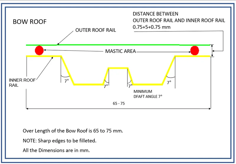
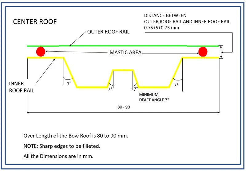
Front roof rails, rear roof rails, center roof rails and bow roof rails design which are given with the mastics and spot welding operation is carried on roof flanges.
design consideration of roof:
1. Visibility criteria.
2. head room clearance
3. Curvature study
4. heat distortion and snow load criteria
5. draft analysis
6. Safety parameters
Roof crush test :
Safety point of view vehicle roof plays very crucial role specially roll over kind of accidents, in which vehicle tips over onto its side of roof. And vehicle rollover crashes are the causes of many fatalities and several head, neck and spine trauma around the world. Therefore, passenger safety is also very important parameter in front of OEM’s. It is not only a marketing strategy but also it is a obligation stipulated by international standards that are now place in several countries, as well as a governmental requirement.
Rollover crashes, especially in the country, are usually very destructive events. Vehicle damage often includes deformation of the roof and its supporting structures. Head and neck injuries are common, and associated with roof deformation. Strengthening of the roof is suggested as an appropriate countermeasure for such injuries.
Types of Rollovers
- Tripped-NHTSA data show that 95% of single-vehicle rollovers are tripped. This happens when a vehicle leaves the roadway and slides sideways, digging its tires into soft soil or striking an object such as a curb or guardrail. The high tripping force applied to the tires in these situations can cause the vehicle to roll over. E.g. Soft soil, Guardrail, Steep Slope
- Un-Tripped -Un-tripped rollovers are less common than tripped rollovers, occurring less than 5% of the time, and mostly to top-heavy vehicles. Instead of an object serving as a tripping mechanism, un-tripped rollovers usually occur during high-speed collision avoidance manoeuvres.
For this reason, strength is very important criteria for designing vehicle roof.
Once the test vehicle has been acquired, either the driver or passenger side of the vehicle is selected for
testing. For most vehicles, the test side is chosen at random. However, for roof designs that appear
asymmetrical, engineering judgment is used to select the side of the roof that may result in a lower peak
force
Testing position according to standards:
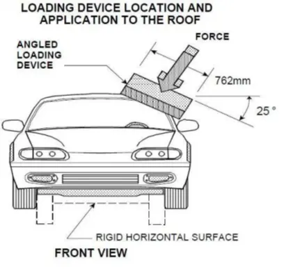
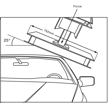
With the vehicle on a level surface, the on-road pitch angle at the front door sill is measured on both sides
of the vehicle. Unless the vehicle manufacturer requests otherwise, roof racks and other nonstructural
items that may be contacted during the test are left as installed from the factory. Any trim or other
components are removed if they interfere with supporting the vehicle along its rocker panels.
For vehicles with vertical pinch weld flanges on the bottom of the rocker panels, the vehicle support
system consists of one I-beam (HR A-36, W4X13) for each rocker panel. Each I-beam has a clamping
system incorporated on the top that is tightened against the pinch weld flange to clamp the system in place
(Figures 1 and 2).
When the pinch weld flange has a bend that prevents supporting the sill with one I-beam, more than one
I-beam can be used on each side of the vehicle. For vehicles with no pinch weld flange, or with a
nonvertical flange angle that precludes clamping, mounting by another method may be necessary, such as
that described in the National Highway Traffic Safety Administration’s Laboratory Test Procedure
(2006).
Prior to testing, the front-row seat back on the side being tested is reclined to prevent interaction with the
crushing roof. Rear seats are latched in their upright position. All windows are closed and doors are
locked.
TESTING :
Roof strength evaluations are conducted on a quasi-static test system manufactured by MGA ResearchCorporation
The system consists of an upright assembly and an attached loading head that can be fixed at varyingheights from the ground and at pitch angles ranging from −5 to +5 degrees to accommodate testing on thedriver or passenger side.
The roll angle is permanently fixed at 25 degrees.
Four hydraulic actuators control the movement of the platen along two linear guides.
The entire system is mounted on a T-slot bed plate anchored to the floor of the test facility.
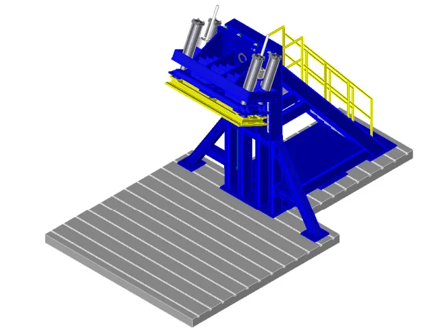
MGA Roof Crush Test System
Two I-beams (HR A-36 W10x88) are mounted on the bed plate perpendicular to the longitudinal axis of the platen. The vehicle, with the attached rocker panel support system, is placed on these beams.
The vehicle is adjusted so that:
1. The longitudinal centerline of platen is within 10 mm of the initial roof contact point.
2. The yaw angle of the vehicle relative to the longitudinal axis of the platen is 0 ± 0.5 degrees.
3. The midpoint of the platen’s forward edge is 254 ± 10 mm beyond the most forward point of the
roof (including the windshield trim if it overlaps the roof) lying on the vehicle’s longitudinal
centerline.
To minimize the potential for loading the edge of the platen during the test, there should be a minimum clearance of 150 mm between every point along the forward edge of the platen and the structurally significant body components, when measured normal to the platen’s face
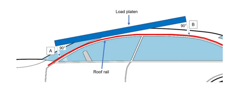
Vehicle Position at the Initial Contact Point
4. The pitch angle of the vehicle matches the on-road angle, while also accounting for any difference
between the platen’s pitch angle and the nominal −5 degrees.
components of the roof:
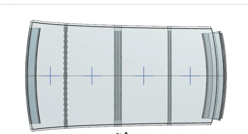
1. Outer roof panel
2. front roof rail
3. bow roof rail 1
4. center roof rail
5. bow roof rail 2
6. rear roof rail
Outer roof rail:
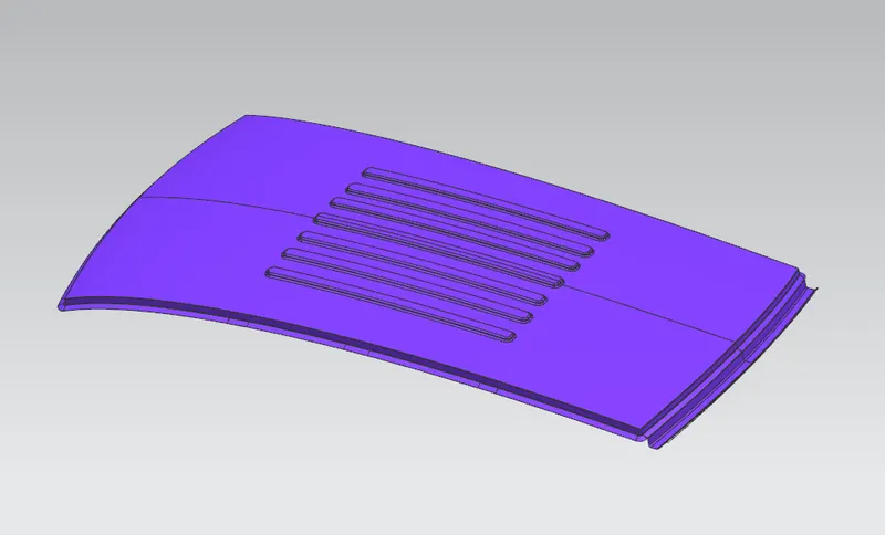
Front roof rail:
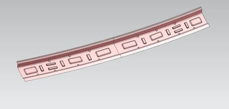
Bow roof rail :
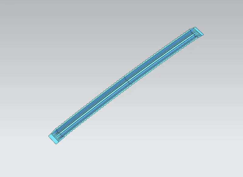
center roof rail:
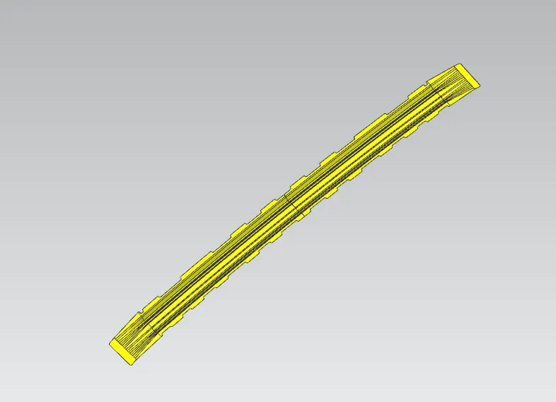
bow roof rail 2:
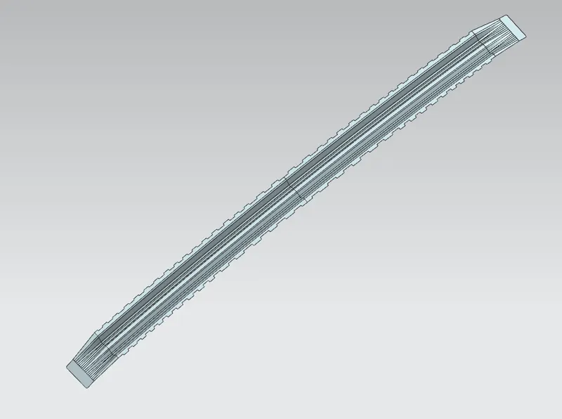
rear roof rail :
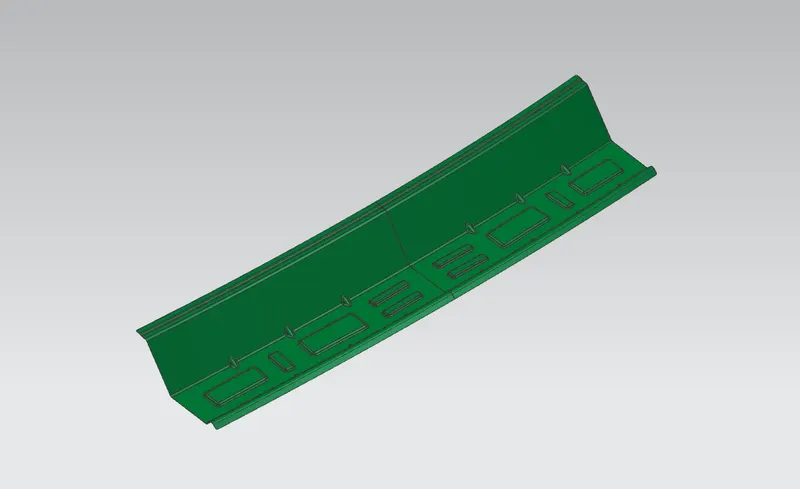
Master section are given for the reinforcements given above:
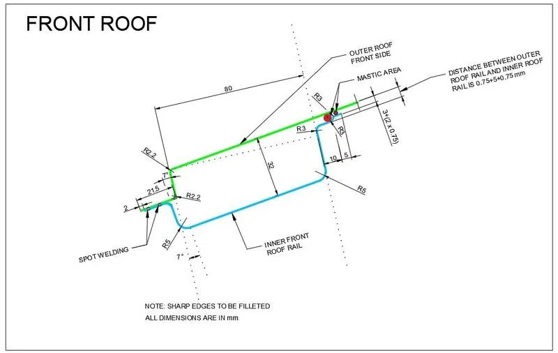
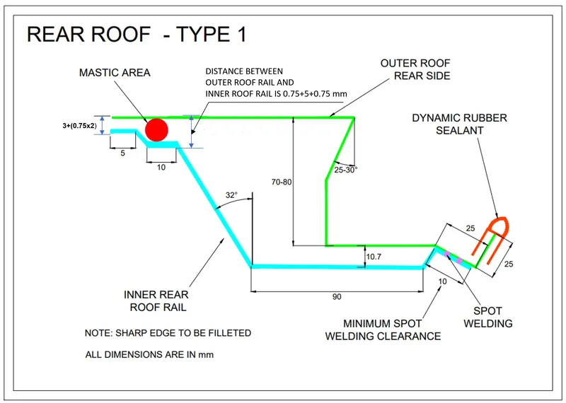
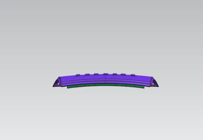
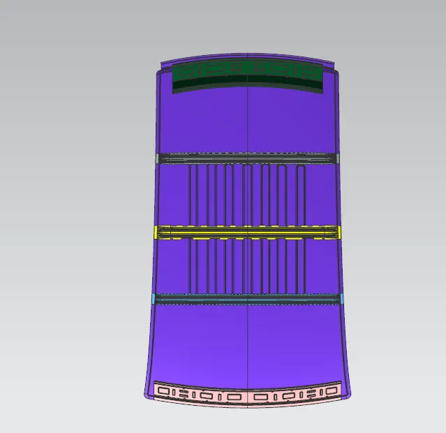
Different views:
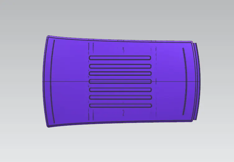
top view:
front view:
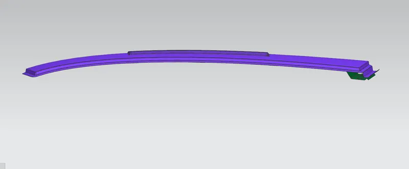
side view:
bottom view:
Design calculation of roof :
To make sure the roof design passes the analysis test some of the criteria to be considered before the design of bow rails under the roof.
they are,
1. Heated ditortion study on the roof
2. Snow load condition
Heated ditortion study on the roof:
In sheetmetal design heat plays a vital role, the temperature sholud limited above which the material cannot be used for the structural application. this study predicts the heat distortion temperature at the material where it start to soften when exposed to a fixed load at elevated temperature. in order to avoid any bending over the roof by stress. by this prediction we can study the positions of the bow roof to strengthen the roof.
Bow–Roof Prediction Formula :
W = [1.73 x 10^(-3) x L] + [1.85 x 10^(-8) x (R^2)/t] + [ 1.10x10^(-3) x l] - 2.68
Where,
L = Roof Length in X-Direction[mm](Roof dimension in 0-Y)
R = Roof curvature
R = 2(Rx*Ry)/(Rx+Ry)
Rx = X curvature
Ry = Y curvature
t = Roof plate thickness [mm]
l = Bow Roof Span [mm]
Judgment Condition
OK< 2.7
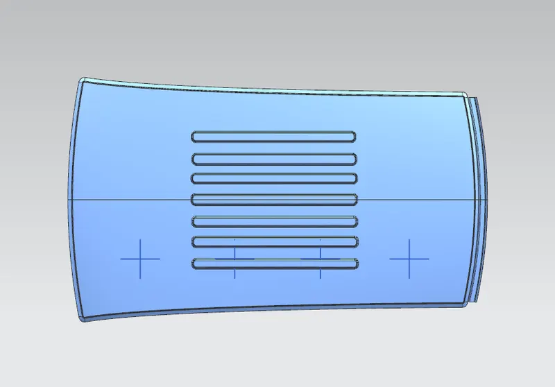
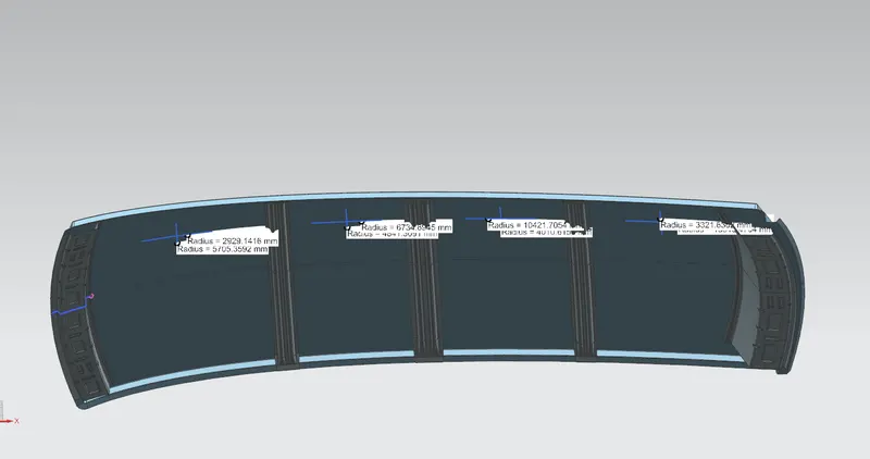
To find the Rx and Ry value :
- first we will create a center line with length same as the roof from top view
- then from the reference line drawn move for the distance 100 to both sides up and down or we can use the offset command to both sides.
- using the radius of verical line(Rx) and radius of the horizontal line (Ry) can calculate the heat distortion.
HEAT DISTORSION TABLE:
|
Sl. no |
Bow roof |
Rx |
Ry |
R |
t |
I |
L |
R^2/t |
W |
RESULT |
|
1. |
Front to Bow 1 |
5705.35 |
2929.14 |
3870.94 |
0.75 |
6.8*10^3 |
2030.64 |
51612588.6 |
0.833 |
OK |
|
2. |
Bow 1 To centre |
4841.30 |
6734.69 |
5633.15 |
0.75 |
1.1*10^3 |
2030.64 |
42309982.4 |
1.615 |
OK |
|
3. |
Centre to Bow 2 |
4010.61 |
10421.70 |
5792.48 |
0.75 |
1.7*10^3 |
2030.64 |
44737161.9 |
1.66 |
OK |
|
4. |
Bow 2 To Back |
3321.63 |
13818.44 |
6487.32 |
0.75 |
1.3*10^3 |
2030.64 |
56113768.8 |
1.87 |
OK |
The test value infer that the design is good and under the limit of standards
Snow Load Prediction Formula
Snow Load criteria:
Snow load criteria study is done to check the ability of the to withstand snowfall and bounce back to its orginal shape without any permenant deformation once the load is removed.
- To calculate the snow load condition, we have a snow load formula
- To measure the required values
- Created a sketch and draw a line on OY axis from the center of the roof
- From that line draw a parallel line distance of 100mm on both sides
- Then make intersection points of these lines and draw a three point arc
Qr = [Iy x t2] / [α x s x [(Rx + Ry)/2]2 x 10-8]
Note: The Qr value given over here is correct. There was a typo error in the formula given in the video.
Where,
α = My x Lx2 x 10-12 , My = Y(Ly-Y)
t = Roof plate thickness [mm]
Ly = Distance between the front and rear roof Rails on the Vehicle along with 0Y[mm]
Length of Roof panel with the center point between Roof rail Front /Rear as the front and rear reference point.
Lx = Distance between the Left and Right end of the roof on the Roof BOW [mm]
The width of the roof panel is exposed on the surface.
Y = Distance front Front Roof Rail to Roof BOW[mm]
s = Distance for which Roof BOW bears divided load [mm]
s = L1/2 + L2/2
Iy = Geometrical moment of inertia of Roof BOW (Y cross-section )[mm4]
Rx = Lateral direction curvature radius of roof panel Y cross-section on Roof BOW [mm]
Roof panel curvature Radius of the Length Lx in Front view
Ry = Longitudinal Direction curvature radius of the Roof panel X cross-section on Roof BOW [mm]
Roof panel X curvature radius of length s in Side view
Judgment condition
Qr ≥ 3.1
250 ≤ s ≤ 380
TABLE OF SNOW LOAD CRITERIA:
|
Sl. No |
Bow roof |
Rx |
Ry |
Lx |
Ly |
L1 |
L2 |
t |
Y |
S |
My |
Iy |
Qr |
RESULT |
|
1. |
Front To Bow 1 |
3798.79 |
6657.48 |
1082.5091 |
2030.204 |
393.37 |
367.22 |
0.75 |
579.92 |
380.30 |
841056.93 |
1172.26 |
4.43E |
OK |
|
2. |
Bow 1 To centre |
4142.09 |
10887.45 |
1059.2194 |
2030.204 |
367.22 |
324.68 |
0.75 |
980.36 |
345.95 |
1029226.02 |
1702.68 |
8.5E |
OK |
|
3. |
Centre To Bow 2 |
4073.84 |
16014.8 |
1044.9704 |
2030.204 |
324.68 |
502.62 |
0.75 |
11845.5 |
413.65 |
8620770.35 |
1306.17 |
3.6E |
OK |
The test value infer that the design is good and under the limit of standards.
Section Modulus :
Section modulus is a direct measure of strength of any sectional area of an object about an referance axis(neutral axis). Strength is nothing but,capable of supporting greater loads,so higher the strength it has a high capable of supporting greater loads.
Section modulus represented with a symbol of ‘S’
S=I/Y
S-Section modulus
I- Moment of inertia
Y- Distance from the neutral axis to any given fiber.
Section modulus of bow roof :
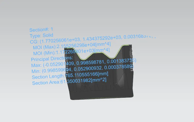
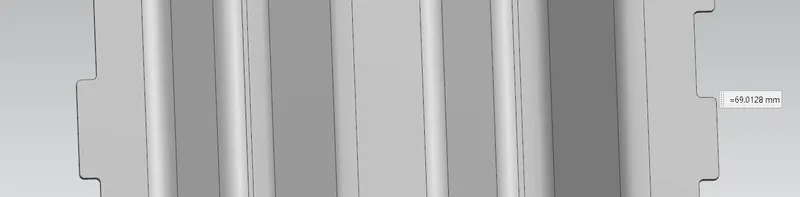
given :
I(max)= 2155.2(mm^4)
I(min)= 1172.2(mm^4)
section modulus = moment of inertia / Distance from the neutral axis to any given fiber
S = I(max) / Y
Y = 69.012mm
S = 2152.2 (mm^4) / 69.12 (mm)
Smax = 31.137 mm^3
Center roof section modulus:
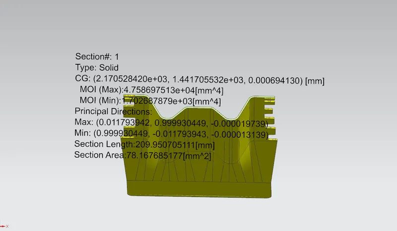
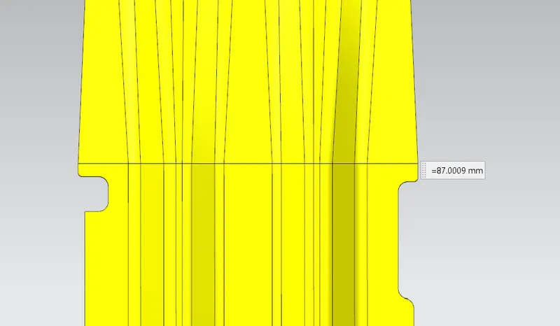
given :
I(max)= 4758.69(mm^4)
I(min)= 1702.68(mm^4)
section modulus = moment of inertia / Distance from the neutral axis to any given fiber
S = I(max) / Y
Y = 87.0009mm
S = 4758.69 (mm^4) / 87.0009 (mm)
Smax = 54.69 mm^3
Bow roof section modulus:
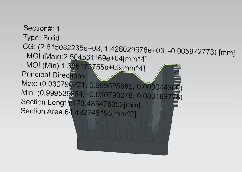
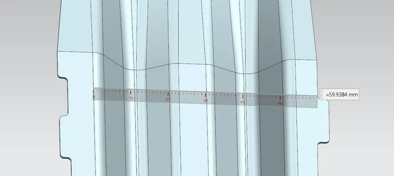
given :
I(max)= 2504.56(mm^4)
I(min)= 1306.17(mm^4)
section modulus = moment of inertia / Distance from the neutral axis to any given fiber
S = I(max) / Y
Y = 59.93mm
S = 2504.56 (mm^4) / 59.93 (mm)
Smax = 41.79 mm^3
DRAFT ANALYSIS:
It is done to check if the features designed clear the minimum draft 7 degree for manufacturabililty. This type of analysis is performed based on color ranges identifying zones on the analyzed element where the deviation from the draft direction at any point, corresponds to specified values.
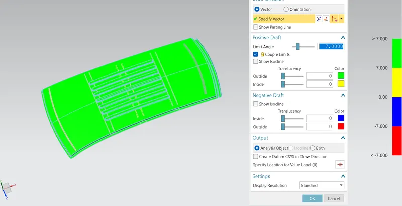
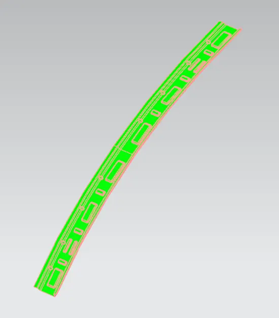
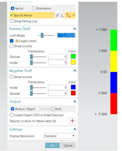
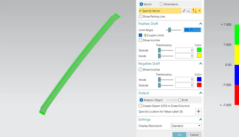
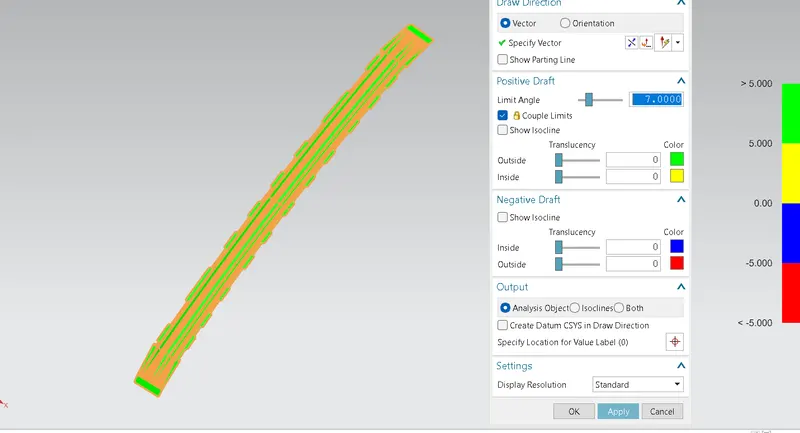
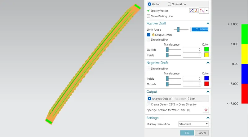

It is seen that the features designed clears the minimum draft angle which denoted in 'green'
CONCLUSION:
Thus the required reinforcement and the ditch area for the roof designed and developed from the given styling.
Curvature study on roof was analysied with heat distortion and snow load standards.
Draft analysis was done to check toolablilty.