Roof Design
ROOF DESIGN
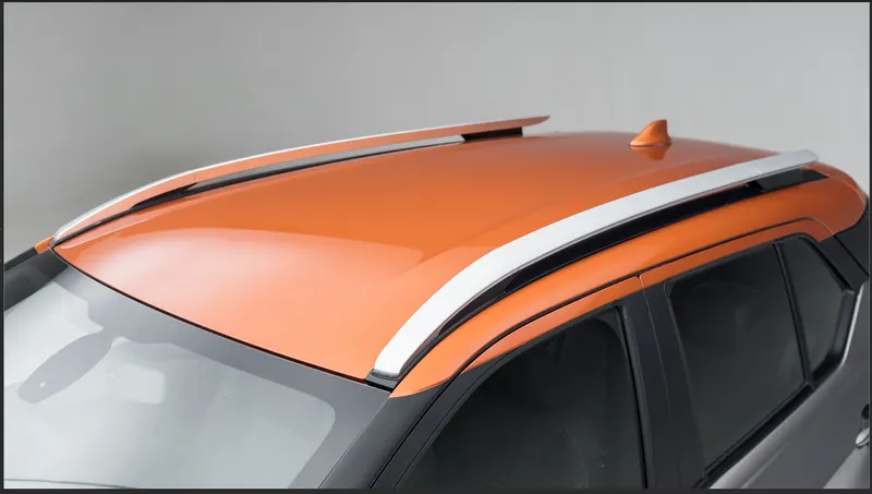
OBJECTIVE :
- The objective of this project is to design car roof with essential flanges and reinforcements like ditch area , front roof rail , bow roofs, central roof rail and rear roof rail for the the given styling surface
- Perform a curvature study on the roof and perform the calculations for the heat distortion and snow load criteria to determine whether the bow roofs are at the correct positions.
- Finding moment of inertia and section modulus for Bow roofs , central roof rail . front roof rail and rear roof rail .
- Perform the draft analysis for each reinforcements
SOFTWARE USED :
NX -CAD
INTRODUCTION :
Design of any product starts from an requirement . The design engineer sketches the product based on the the requirement . Then the 2D sketch with the proper dimensions is converted into the 3D model using the advanced CAD software's . The another important thing in the design is that , every product that is designed should be able to manufactured . so the role of the design engineer is to design the product that can be easily manufactured and with less cost effective . This is the place where the Design for manufacturing [DFM] and Design of assembly [DFA] takes a role while developing any product . The process of development of design carries on until the design satisfies the customer needs .Here in this project the product that we are going to develop is a car roof
CAR ROOF :
An automobile roof or car top is the portion of an automobile that sits above the passenger compartment, protecting the vehicle occupants from sun, wind, rain, and other external elements. Roof is the structure above the wind shield glass having the reinforcements to provide the strength to the overall structure and to with stand the over head forces like snow
WHY REINFORCEMENTS :
If the roof is flat it is very weak and cannot able to with stand the forces like snow , so in order to increase the strength of the roof these reinforcements like front roof rail, central roof rail, rear roof rail and the bow roofs are introduced and joined to the flat surface of the roof with the different joining process
DESCRIPTION
DESIGN CONSIDERATION-
-
Visibility criteria
-
Head clearance
-
Curvature study
-
Hear distortion and snow load criteria
-
Draft analysis.
Components of roof-
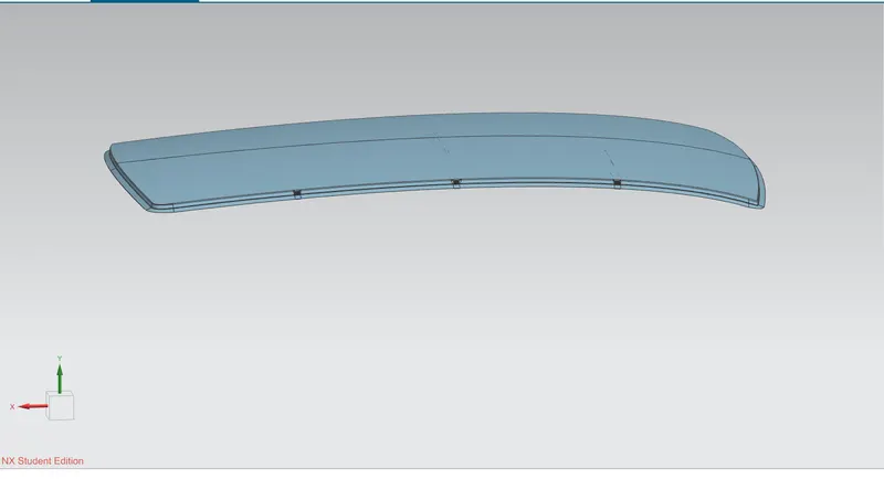
1.Front Roof Rail-
The front roof rail is located on the front of the roof where the wind shield joins with the roof. The visibility criteria and the head room clearance of the passenger are taken into consideration for the bottom flange. One end of the rail is joined using spot welding while the other end is joined with the roof using mastic sealants for increased strength.
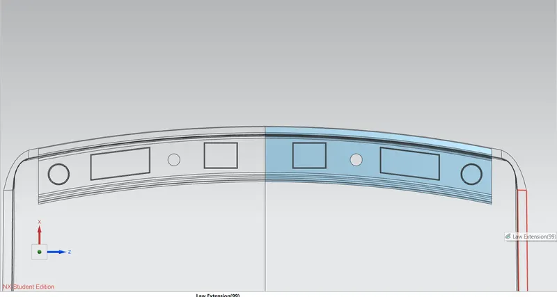
2.Bow roof 1-
Bow roof is an additional siffening member for the roof to increase the strength and so that it can satisfy the norms. Both the ends are joined together using mastic sealants to increase strenght and also since this would not affect the styling of the roof.
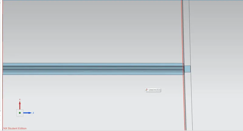
3.Centre Roof Rail-
Centre Roof rail or the reinforcement centre is located at the centre of the roof . The cross section of this is more since it needs to provide more strength to the roof. Here both are ends are joined together using mastic sealants.
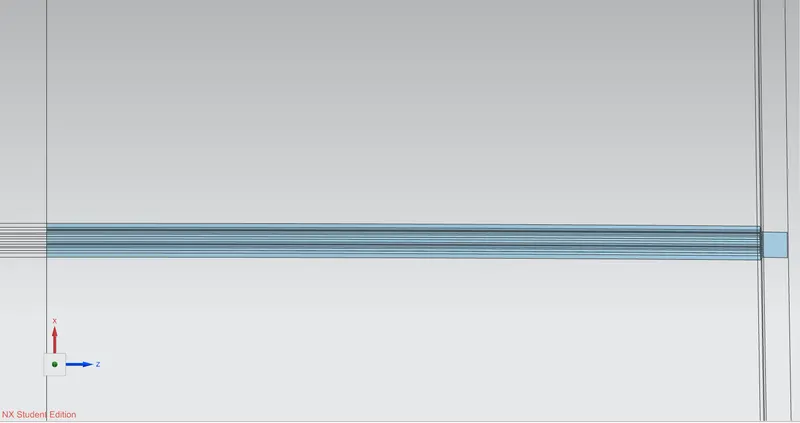
4.Rear Roof Rail.
This roof rail joins with the back door and the roof. Inputs from the backdoor are taken into consideration for designing this roof rail.
Here one end is joined using spot welding while the other end is joined using mastic sealants.
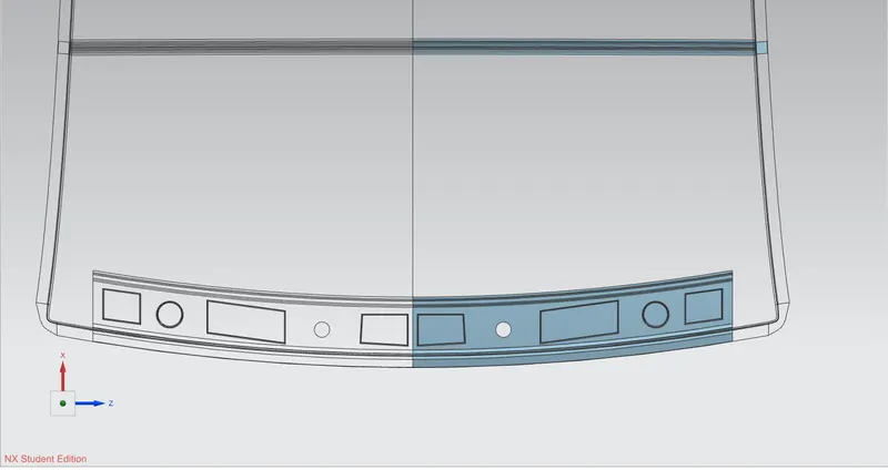
We then also make the ditch area around the roof.
Ditch area the extended portion of the main roof concealed by other BIW panels.
ROOF CRUSH TEST :
Roof crush test is the design given by the IIHS ( insurance institute of highway safety ) . After analyzing the many accidents IIHS has then fixed some regulations , that how to perform the crush test .
IIHS gives the rating based up on this test . For this they consider two points while giving the rating
- How fast the car can reforms to its original shape after the roll over and
- How deep is the protrusion after the roll over
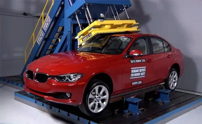
GOAL OF ROOF CRUSH TEST :
To minimize the protrusion into the occupant compartment , so that the seat belts and air bags can do there job in protecting the occupant
CONDITIONS TO FOLLOW FOR ROOF CRUSH TEST :
There are two conditions that should be followed for the roof crush test , they are
INITIAL CONDITION :
- Close and lock all the doors
- Close all the windows
SECOND CONDITION :
Fix the body sill or chassis frame on a hard lever surface horizontally
METHOD OF APPLYING THE FORCE :
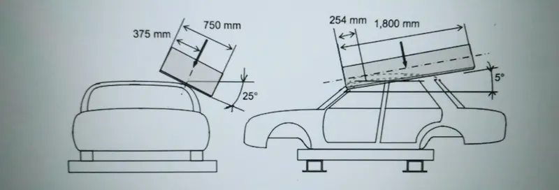
The load is applied in such a way that 50 is tilted from the front end to the rear end and the load will be in 1800 mm in length and 750 mm in width . The load is applied at the position of 250 from the flatness of the roof . The load is applied on the roof for almost 120 sec and the crush speed at which the load applied is 13 mm/sec or less than that
RESULTS :
If the displacements goes above the requirements level then we have to increase the bow roof thickness or add more mastics points to increase the strength . the stronger the roof the better it can protect the occupants in the roll over crashes.
HEAT DISTORTION STUDY ON THE ROOF :
The heat distortion study plays a major role in sheet metal usage . heat distortion temperature is a temperature limit above which the material cannot be used for the structural applications . This study is used to predict the heat distortion temperature at where the material starts to soften when exposed to a fixed load at elevated temperature . In order to avoid bending or damages on the roof, based on the heat distortion temperature , this study will predict the bow roof position which helps to strengthen the roof .
CALCULATIONS
Heat Distortion Curvature Study-
This study is used to find out and predict the heat distortion temperature at where the material starts to soften when exposed to a fixed load. So in order to avoid bending or damage of the roof based on this calculation we will decide the position on the roof bows on the roof.
Formula-
W = [1.73 x 10^(-3) x L] + [1.85 x 10^(-8) x (R^2)/t] + [ 1.10x10^(-3) x l] - 2.68
Judgement Condition : OK< 2.7> 3.1
Where,
L = Roof Length in X-Direction[mm](Roof dimension in 0-Y)
R = Roof curvature
R = 2(Rx*Ry)/(Rx+Ry)
Rx = X curvature
Ry = Y curvature
t = Roof plate thickness [mm]
l = Bow Roof Span [mm]
Result:
|
Bow position |
Rx |
Ry |
R |
l |
L |
t |
R2/2 |
W |
OK/NG |
|
FR and 1st |
5626.39 |
3067.66 |
3970.5 |
448.56 |
2033.7 |
1.5 |
21019825.94 |
1.53 |
OK |
|
1st and CTR |
4854.3 |
6624.76 |
5602.99 |
365.81 |
2033.7 |
1.5 |
41858066.77 |
1.63 |
OK |
|
CTR and 2nd |
4065.16 |
10593.91 |
5875.67 |
463.2 |
2033.7 |
1.5 |
46031333.73 |
1.77 |
OK |
|
2nd and RR |
3424.34 |
14478.23 |
5538.68 |
352.33 |
2033.7 |
1.5 |
40902692.46 |
1.6 |
OK |
Snow Load Criteria-
We predict the snow load in this of the roof bows and then place and change the design of the load accordingly to satisfy the condition.
Formula-
Qr =[Iy x t2] / [α x s x [(Rx + Ry)/2]2 x 10-8]
Note: The Qr value given over here is correct. There was a typo error in the formula given in the video.
Where
α = My x Lx2 x 10-12 , My = Y(Ly-Y)
Judgement condition = Qr ≥ 3.1
250 ≤ s ≤ 380
t = Roof plate thickness [mm]
Ly = Distance between the front and rear roof Rails on the Vehicle along with 0Y[mm]
Length of Roof panel with the center point between Roof rail Front /Rear as the reference point of the front and the rear.
Lx= Distance between the Left and Right end of the roof on the Roof BOW [mm]
Width of the roof panel exposed on the surface.
Y = Distance front Front Roof Rail to Roof BOW[mm]
s= Distance for which Roof BOW bears divided load [mm]
s = L1/2 + L2/2
Iy = Geometrical moment of inertia of Roof BOW (Y cross-section )[mm4]
Rx = Lateral direction curvature radius of roof panel Y cross-section on Roof BOW [mm]
Roof panel curvature Radius of the Length Lx in Front view
Ry = Longitudinal Direction curvature radius of the Roof panel X cross-section on Roof BOW [mm]
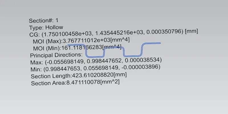
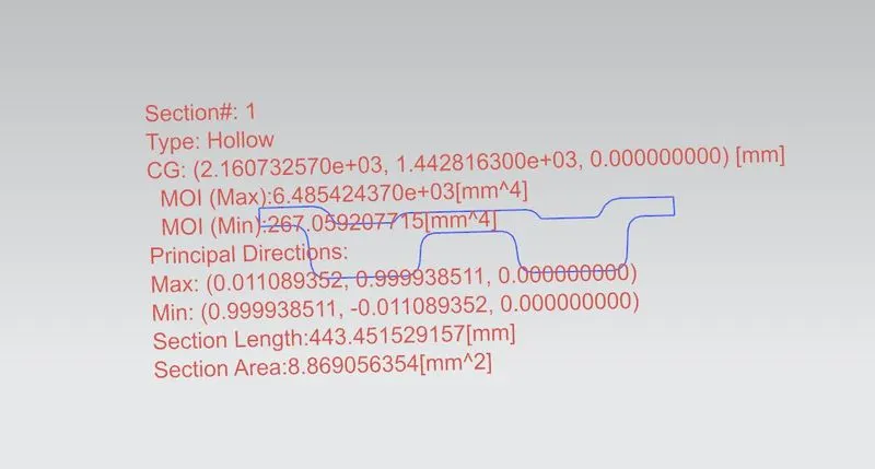
Moment of inertia-
Bow roof 1-
Centre bow roof-
Bow roof 2-
Result-
|
Bow position |
Iy |
α |
Lx |
Ly |
Y |
S |
Rx |
Ry |
t |
Qr |
Determination |
|
FR and 1st |
161.19 |
1.05 |
1119.69 |
2033.7 |
569.65 |
447.74 |
4105.6 |
15113.26 |
1.5 |
0.84 |
NG |
|
1st and CTR |
267.05 |
1.21 |
1081.72 |
2033.7 |
979.65 |
464.47 |
3794.03 |
10543.14 |
1.5 |
2.09 |
NG |
|
CTR and 2nd |
161.3 |
0.91 |
1059.39 |
2033.7 |
1488.08 |
447.71 |
4231.18 |
6602.02 |
1.5 |
3.03 |
NG |
Now since we these values for the snow load values it does not satisfy the condition.
So to make the roof stronger we create embossses on the roof to strengthen the roof.
Draft analysis-
Before we give the part for manufacturing we have to some analysis ourself to check all the constraints and to check if we have any negative draft on a part .
We have a tool called draft analysis in NX Cad to check the following.
Bow roof 1-
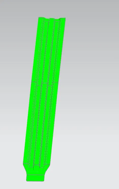
Centre roof rail-
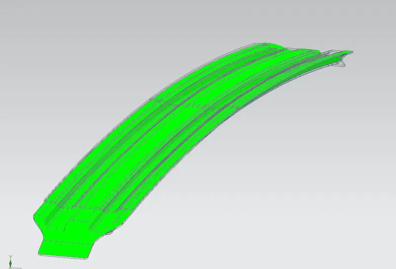
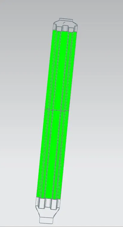
Bow roof 2-
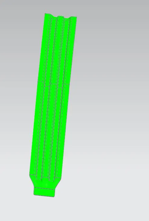
Roof-
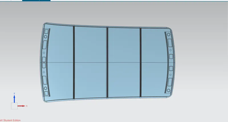
We gave a limit angle of 3 degree.
When the colour is green it means it has a positive draft it means area which are more than 3 degree is shown as green. If it is shwn in yellow that means it has less then 3 degrees and if in blue or red then it means it has negative draft.
Section modulus-
Original-
Smin=147.9884mm3
Offsetting the bottom curve by 0.5mm downwards-
Smin=165.1002mm3
Offsetting the bottom curve by 0.5mm up-
Smin=164.9576mm3
|
CASE |
SECTION |
Imin(mm4) |
Smin(mm3) |
|
1 |
Original |
1.5667x 10⁵ |
147.99 |
|
2 |
Offset 0.5mm down |
1.73099x 10⁵ |
165.1 |
|
3 |
Offset 0.5mm up |
1.7352 x 10⁵ |
164.96 |
From the above observations we can say that when we offset the curve 0.5mm downwards, we get a better section modulus.
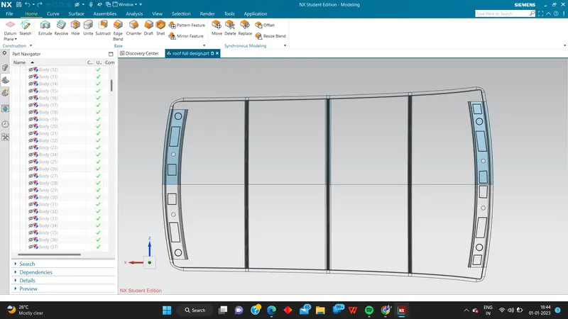
TOP VIEW :
CONCLUSION :
Hence the roof , front roof rail, bow roof rails , central roof rail and the rear roof rail is designed by following the master sections and the moment of inertia and draft analysis are carried out to check feasibility manufacturing..