Roof Design
ABSTRACT
An automobile roof or car top is the portion of an automobile that sits above the passenger compartment, protecting the vehicle occupants from sun, wind, rain, and other external elements. Safety point of view the roof plays vital role,specially on accident where cars roll overs.Roll over accidents are the causes of many fatalities and several head,neck and spinetrauma around the world. Therefore passenger safety is also very important parameter in front of OEMs now a days. It is not only a marketing strategy but also a obligation stipulated by many governments. For this reason the strength of the roof is very crucial while designing the Vehicle roof.
We need to design the required reinforcment and flanges for the given Class A surface of Roof.Required reinforcments are Front Roof Rail,Rear Roof Rail,Bow Roof 1,Bow Roof 2,Bow Roof 3. After designing the roof assembly completely we need to perform the Heat distortion analysis and the Snow Load Analysis.
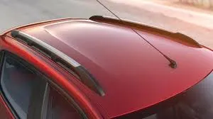
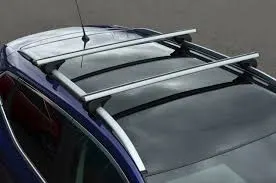
- Sunroofs - A sunroof is a movable panel that opens to uncover a window in an automobile roof, allowing light and/or fresh air to enter the passenger compartment. Sunroofs can be manually operated or motor driven, and are available in many shapes, sizes and styles. While the term sunroof is now used generically to describe any glass panel in the roof, the term "moonroof" was historically used to describe stationary glass panes rigidly mounted in the roof panel over the passenger compartment. A moonroof has a glass panel that is transparent and usually tinted. Previous terms include Sunshine Roof, Sliding Head and Sliding Roof.
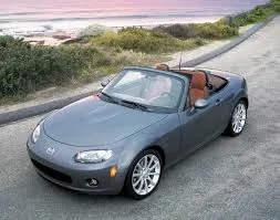
- Convertible roofs - A convertible or cabriolet is a passenger car that can be driven with or without a roof in place. The methods of retracting and storing the roof vary between models. A convertible allows an open-air driving experience, with the ability to provide a roof when required. Potential drawbacks of convertibles are reduced structural rigidity (requiring significant engineering and modification to counteract the effects of removing a car's roof) and cargo space.
Design and Functional Requirements for the Roof :-
While designing of roof following considerations have to be taken into account.
- Visibility Criteria
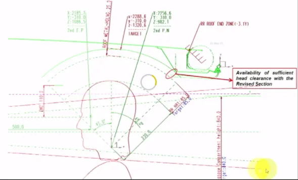
- Head clearance
- Curvature Study
- Head Distortion
- snow load criteria
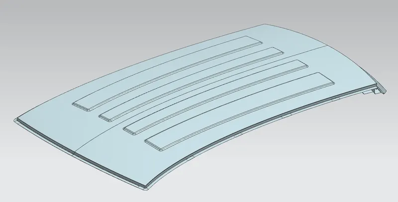
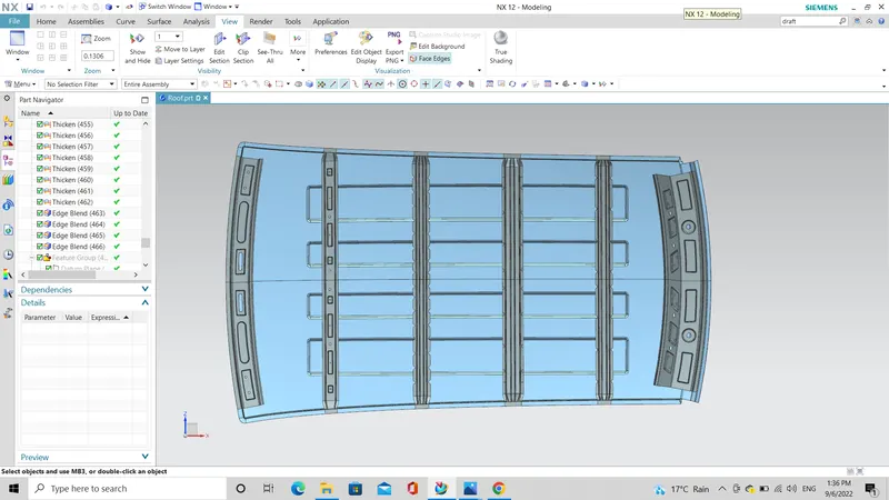
ROOF
FRONT ROOF RAIL
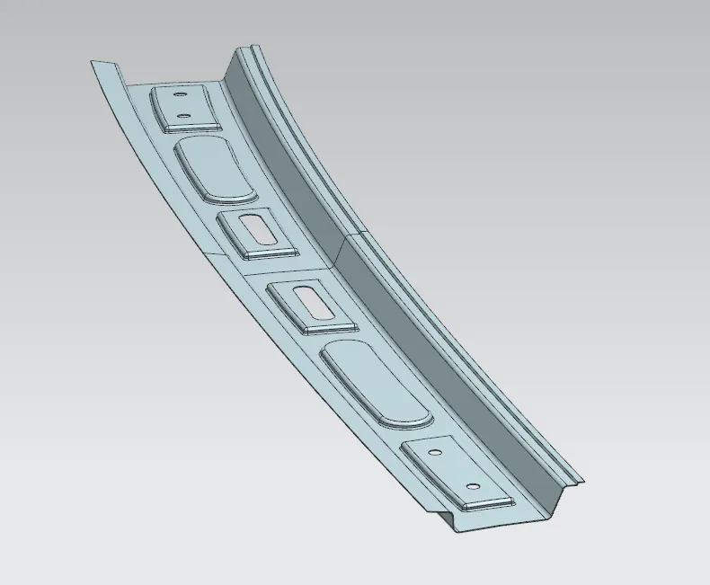
BOW ROOF 1
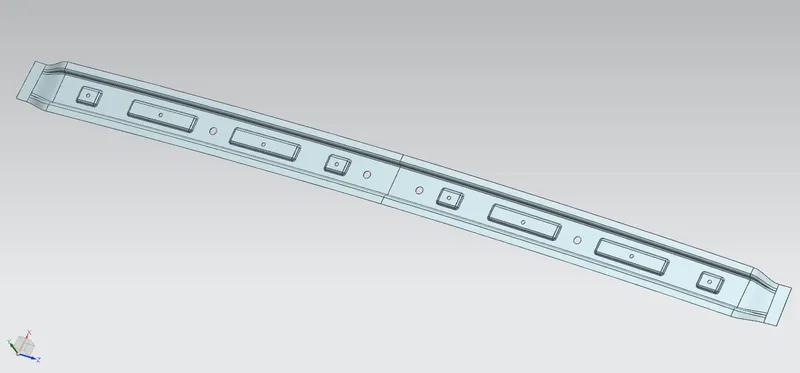
BOW ROOF 2
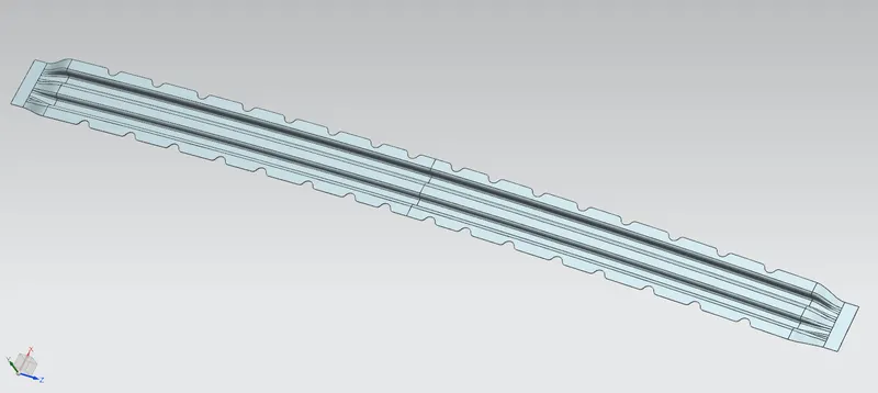
CENTER BOW ROOF
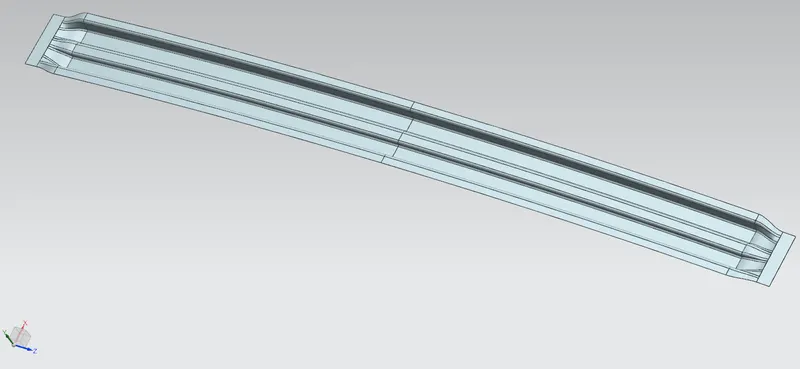
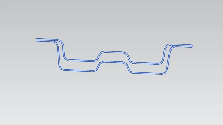
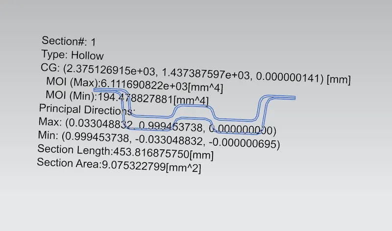
CENTER BOW ROOF REINFORCEMENT
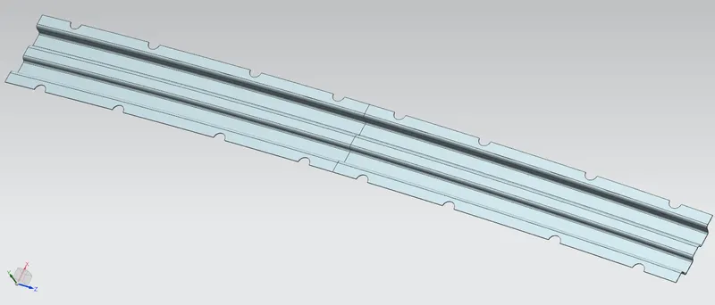
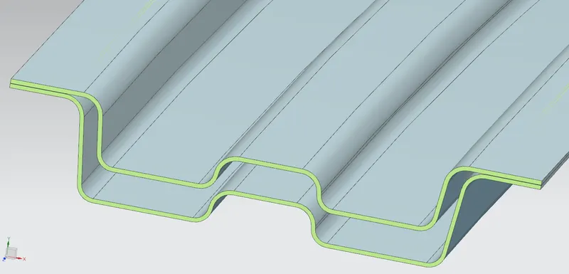
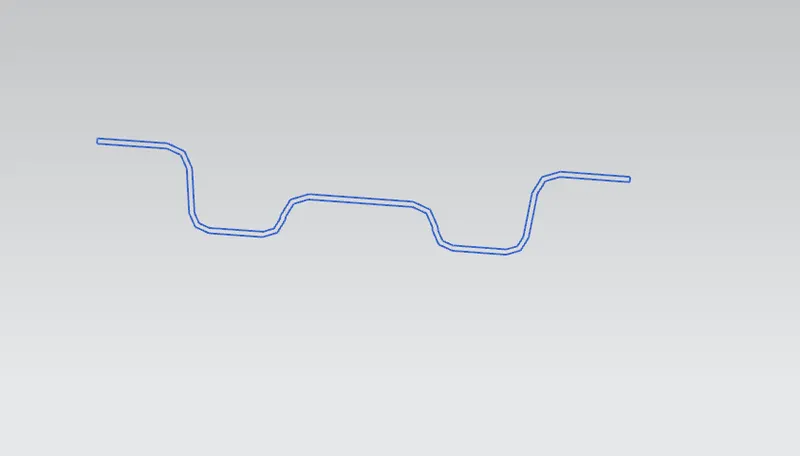
BOW ROOF 3
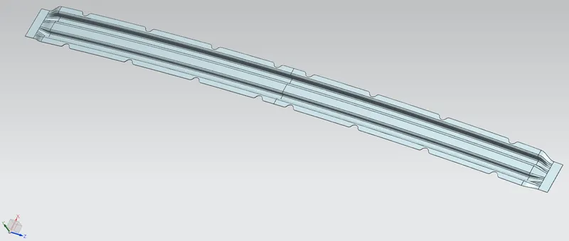
REAR ROOF RAIL
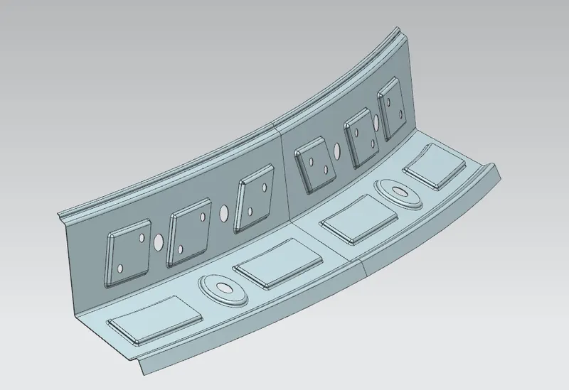
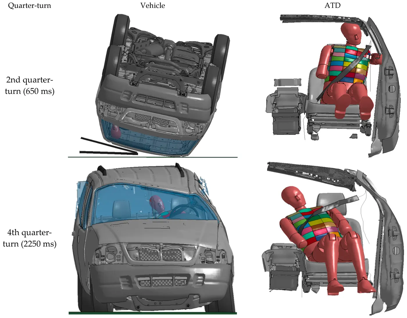
Roll Over Test On Roof :
- The rollover test is given by the Insurance Institute of highway safety ( IIHS). After analyzing many accidents IIHS has fixed some regulations about how to perform the test.
- IIHS rating is based on the following things which are how fast a car can reform its original shape after rollover and how deep a protrusion is.
- The aim of this test is to minimize the protrusion of the roof.
- Two conditions need to be followed while performing this test. One is to lock all the doors of the car properly and the second is to close all the windows of a car.
- Also, it is mandatory to fix the chassis on the hard lever surface horizontally.
Car Roll-over Test - The Roll-over test is conducted because a rollover is a type of vehicle crash in which a vehicle tips over onto its side or roof. Rollovers have a higher fatality rate than other types of vehicle collisions.
- Vehicle rollovers are divided into two categories: tripped and untripped. Tripped rollovers are caused by forces from an external object, such as a curb or a collision with another vehicle. Untripped crashes are the result of steering input, speed, and friction with the ground.
- The vehicles which have a higher center of gravity like SUV or Small Trucks are more prone to Roll-over. Rollover accidents typically involve a singular vehicle that loses control due to icy or snowy road conditions, soft road shoulders, uneven ground, collision with curbs or guardrails after a vehicle has lost traction, or hitting an obstacle while driving.
- During a rollover accident the regional body distribution of injuries normally effects five main areas: head and neck, thorax, abdomen, upper limbs, and lower limbs. The majority of rollover crash victims sustain multiple injuries throughout these regions with the head and neck being the most vulnerable area. Some of the most common rollover injuries include: traumatic brain injury, spinal cord injury, broken bones, and cuts, scrapes, and bruises. These injuries are caused from slamming into another vehicle or obstacle, impact with unsecured cargo, contact with broken glass or torn metal, or from being tossed within the vehicle or ejected from the vehicle.
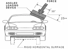
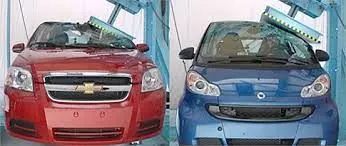
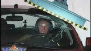
- Roof Crush Test - In this test the load is applied on the roof to test the strength in static car postion. The standard does not apply to school buses and passenger cars that conform to the dynamic rollover test requirements of FMVSS 208, Occupant Crash Protection, and S5.3 by means that require no action by passenger car occupants. It also does not apply to convertibles, except for optional compliance with the standard as an alternative to the rollover test requirements in S5.3 of FMVSS. In April 1991, the National Highway Traffic Safety Administration (NHTSA) announced that FMVSS 216 was to be extended to light trucks, buses and multi-passenger vehicles not exceeding 6000 pounds, and that requirement came into force in September 1993. American statistics have long indicated that the fatality rate when light trucks (including four-wheel drives and utility vehicles) are involved in rollover accidents is twice that for passenger cars.
- The resistance of the vehicle roof to deformation is dictated by a static test, in which the force of 1.5 times the unloaded vehicle weight or 5000 pounds, which is less, is progressively applied to the roof of the vehicle in the region of the “A” pillar.
- Force is applied to the plate at a roll angle of 25 degree and a pitch angle of 5 degree to the direction of the forces simulation can be experienced in rollover crashes. At the t time of the test, displacement of vehicle roof should not more than 5 inches of intrusion, as estimated by the movement of the test device.
Bow–Roof Prediction Formula
W = [1.73 x 10^(-3) x L] + [1.85 x 10^(-8) x (R^2)/t] + [ 1.10x10^(-3) x l] - 2.68
Where,
L = Roof Length in X-Direction[mm](Roof dimension in 0-Y)
R = Roof curvature
R = 2(Rx*Ry)/(Rx+Ry)
Rx = X curvature
Ry = Y curvature
t = Roof plate thickness [mm]
l = Bow Roof Span [mm]
Judgment Condition
OK< 2.7
| Roof Rails | Rx(mm) | Ry(mm) | R(mm) | L(mm) | t(mm) | I(mm) | W | Result |
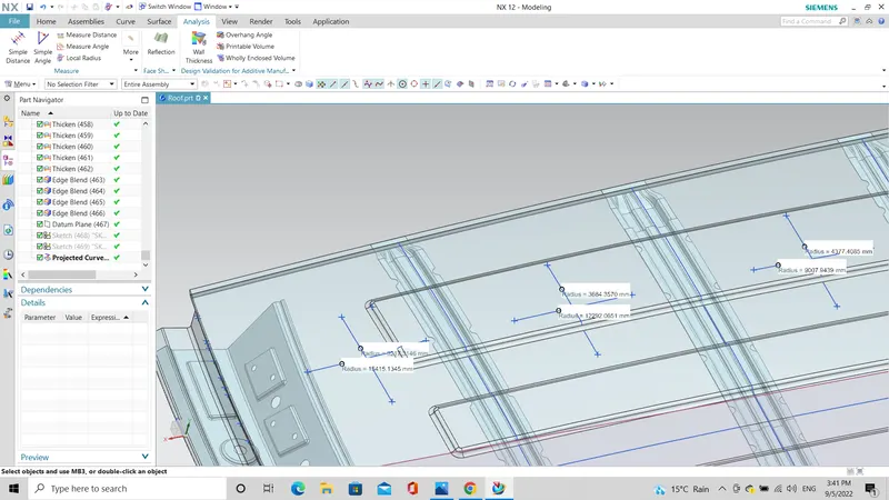
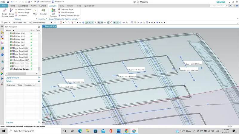
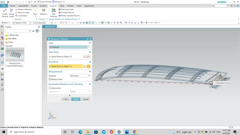
| FR-BR1 | 2701.3906 | 5648.0260 | 3654.7521 | 1919.9212 | 0.75 | 346.3235 | 1.715 | OK |
| BR1-BR2 | 5817.4603 | 5111.7077 | 5441.7969 | 1919.9212 | 0.75 | 399.9049 | 1.355 | OK |
| BR2-CR | 9007.9439 | 4377.4085 | 5891.731 | 1919.9212 | 0.75 | 400.1259 | 1.402 | OK |
| CR-BR3 | 12292.0651 | 3684.3570 | 5669.399 | 1919.9212 | 0.75 | 399.5474 | 1.378 | OK |
| BR3-RR | 15415.1345 | 3217.3146 | 5323.544 | 1919.9212 | 0.75 | 341.2483 | 1.278 | OK |
Sketch for measure the values for the calculation
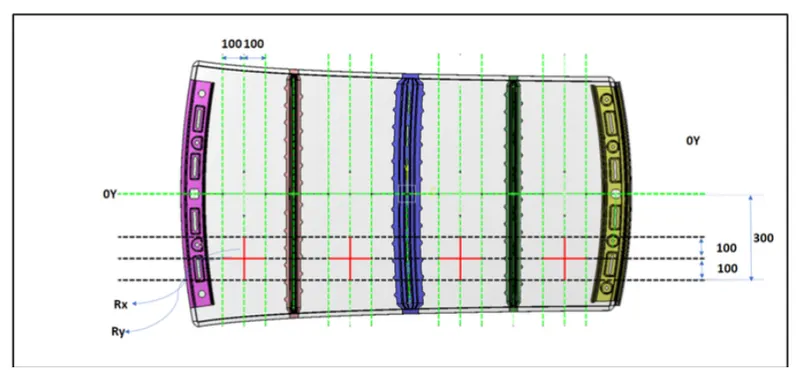
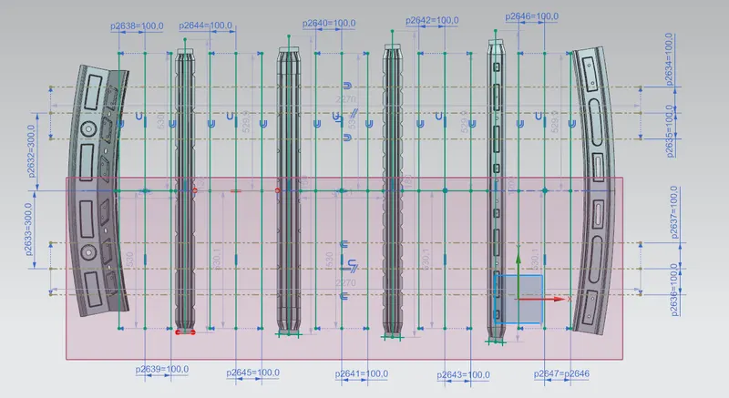
RX AND RY VALUE
L Value
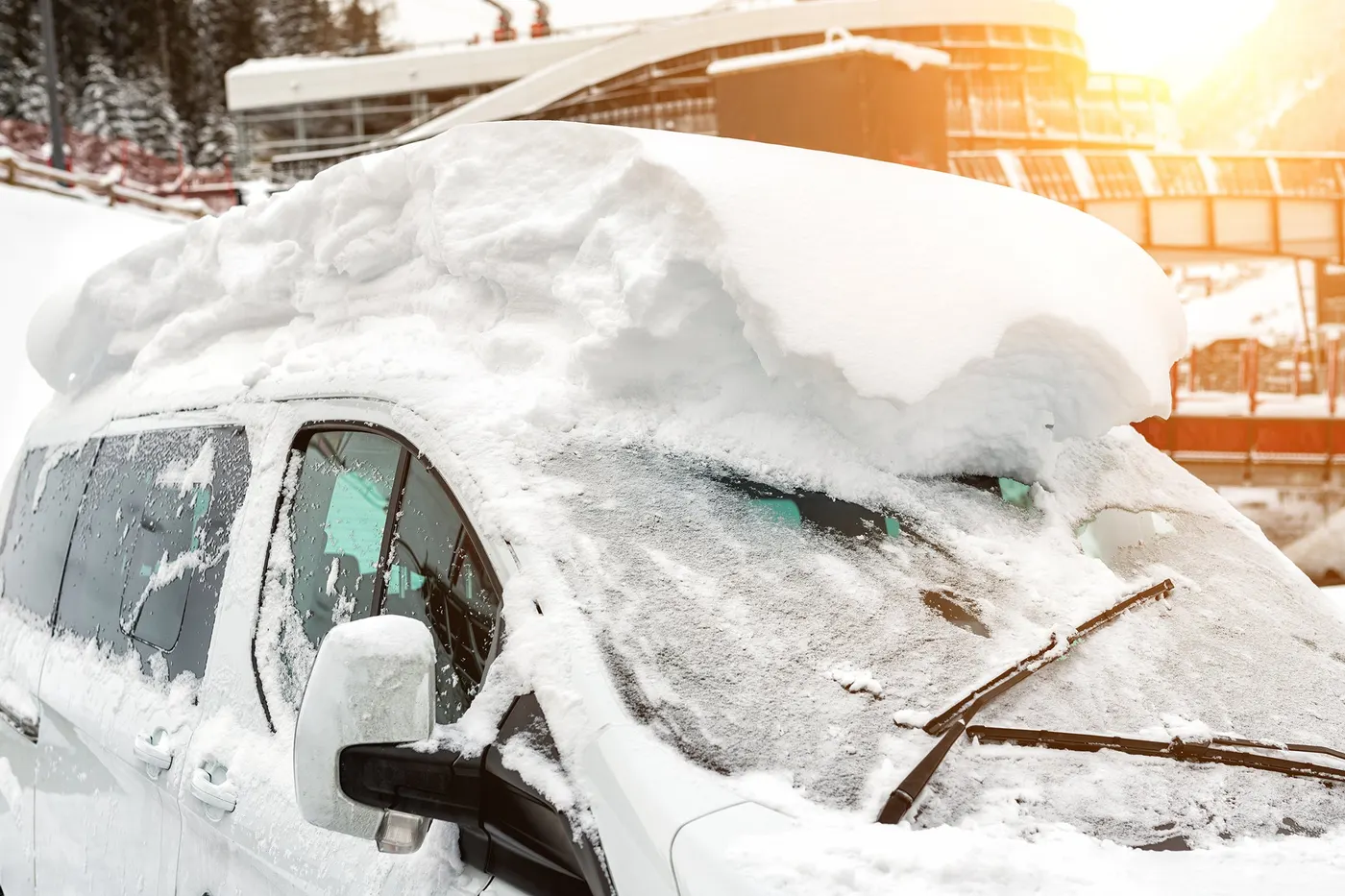
Snow Load Prediction Formula
Qr = [Iy x t2] / [α x s x [(Rx + Ry)/2]2 x 10-8]
Note: The Qr value given over here is correct. There was a typo error in the formula given in the video.
Where,
α = My x Lx2 x 10-12 , My = Y(Ly-Y)
t = Roof plate thickness [mm]
Ly = Distance between the front and rear roof Rails on the Vehicle along with 0Y[mm]
Length of Roof panel with the center point between Roof rail Front /Rear as the front and rear reference point.
Lx = Distance between the Left and Right end of the roof on the Roof BOW [mm]
The width of the roof panel is exposed on the surface.
Y = Distance front Front Roof Rail to Roof BOW[mm]
s = Distance for which Roof BOW bears divided load [mm]
s = L1/2 + L2/2
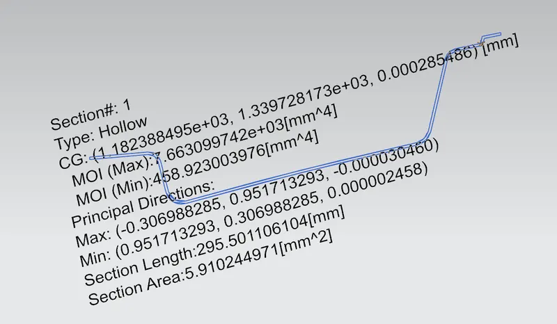
Iy = Geometrical moment of inertia of Roof BOW (Y cross-section )[mm4]
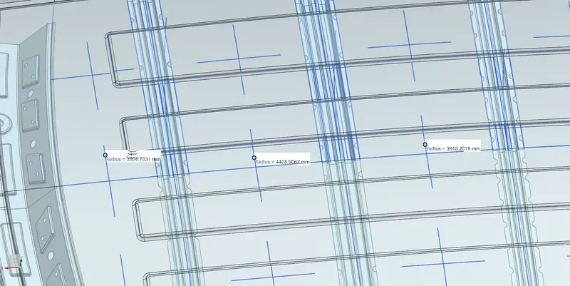
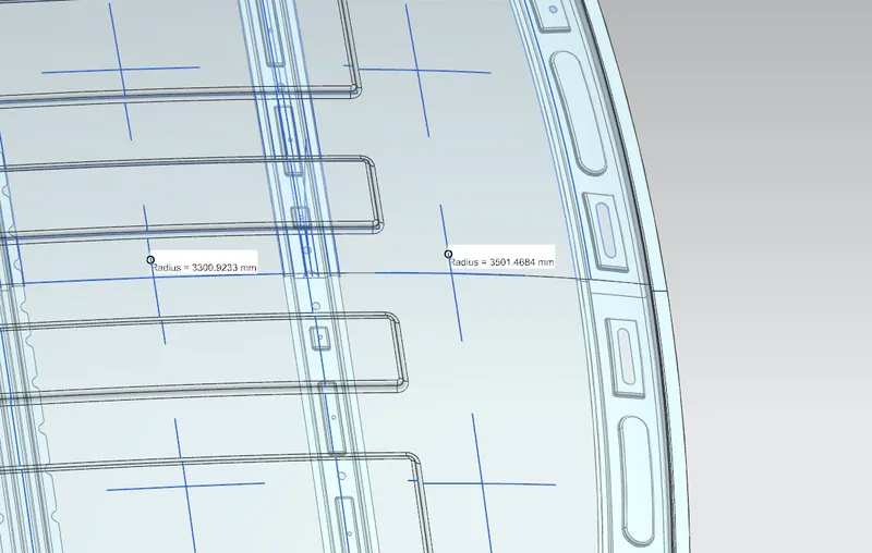
Rx = Lateral direction curvature radius of roof panel Y cross-section on Roof BOW [mm]
Roof panel curvature Radius of the Length Lx in Front view
Ry = Longitudinal Direction curvature radius of the Roof panel X cross-section on Roof BOW [mm]
Roof panel X curvature radius of length s in Side view
| Roof Rail |
Iy (mm^4) |
Lx (mm) |
Ly (mm) |
L1 (mm) |
L2 (mm) |
Rx (mm) |
Ry (mm) |
t (mm) |
Y (mm) |
s (mm) |
α (mm) |
Qr (mm) |
Result |
| FR-BR1 | 458.92 | 1144.2770 | 2244.2763 | 259.5797 | 327.1500 | 2745.9099 | 3501.4684 | 0.75 | 346.3235 | 293.364 | 0.86065 | 10.47 | OK |
| BR1-BR2 | 148.22 | 1101.1478 | 2244.2763 | 327.1500 | 317.2787 | 5223.7984 | 3300.9233 | 0.75 | 399.9049 | 322.214 | 0.89432 | 1.592 | NG |
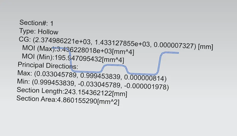
| BR2-CR | 195.947 | 1071.7501 | 2244.2763 | 317.2787 | 317.3685 | 8635.6466 | 3918.2019 | 0.75 | 400.1259 | 317.323 | 0.8475 | 1.04 | NG |
| CR-BR3 | 50.8494 | 1052.4309 | 2244.2763 | 317.3685 | 203.6152 | 13700.5430 | 4468.9062 | 0.75 | 399.5474 | 260.49 | 0.81637 | 0.162 | NG |
| BR3-RR | 5.0659 | 1047.2964 | 2244.2763 | 203.6152 | 17500.1385 | 3504.7031 | 0.75 | 341.2483 | 0.7122 |
Judgment condition
Qr ≥ 3.1
250 ≤ s ≤ 380
RX VALUE
Moment of Inertia
For Front Roof Rail
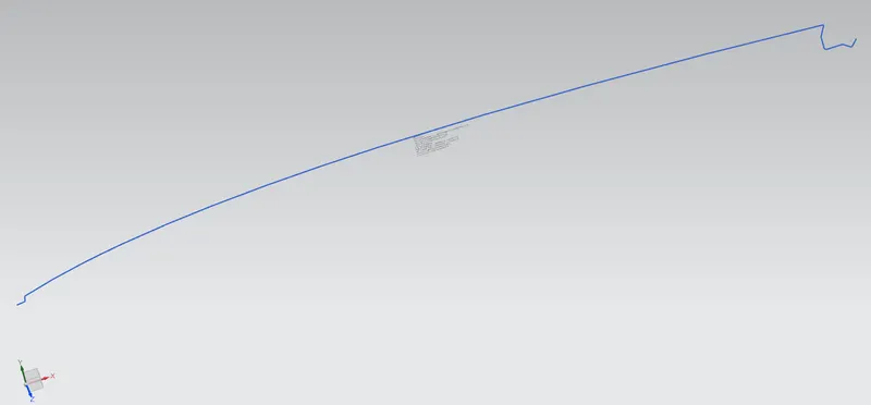
For Roof
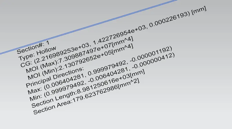
Bow Roof 1
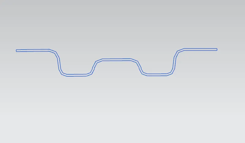
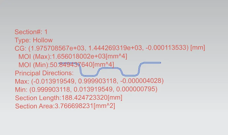
Center Roof Rail
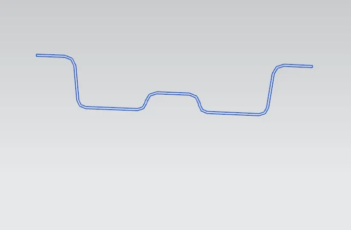
Center Roof Reinforcement
Bow Roof 3
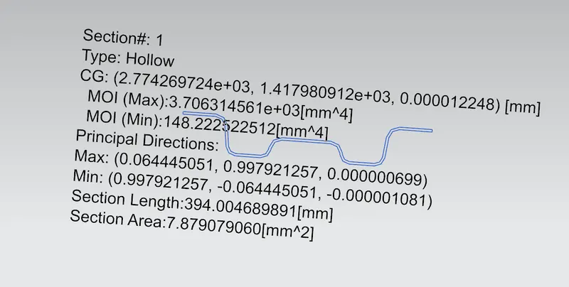
Rear Roof Rail
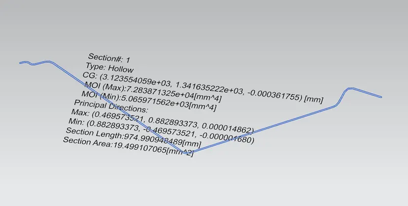
Draft analysis:
ROOF
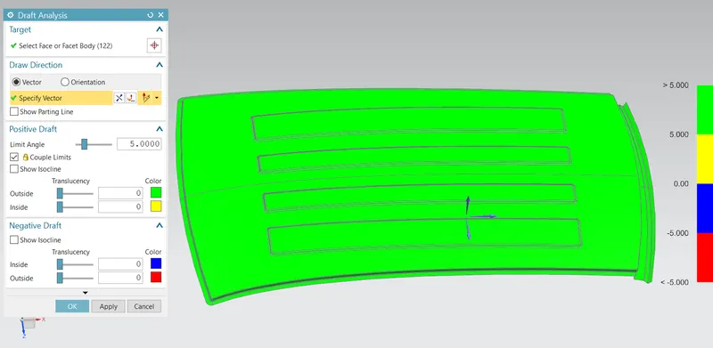
REAR ROOF RAIL
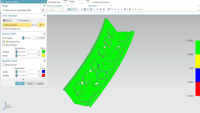
FRONT ROOF RAIL
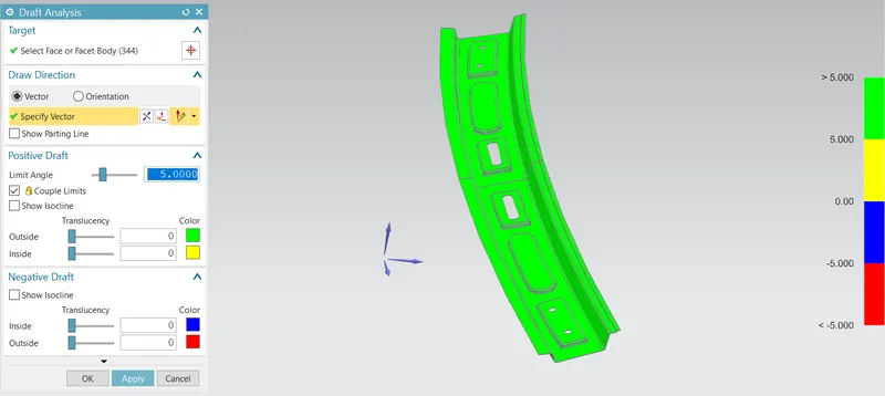
BOW ROOF 1
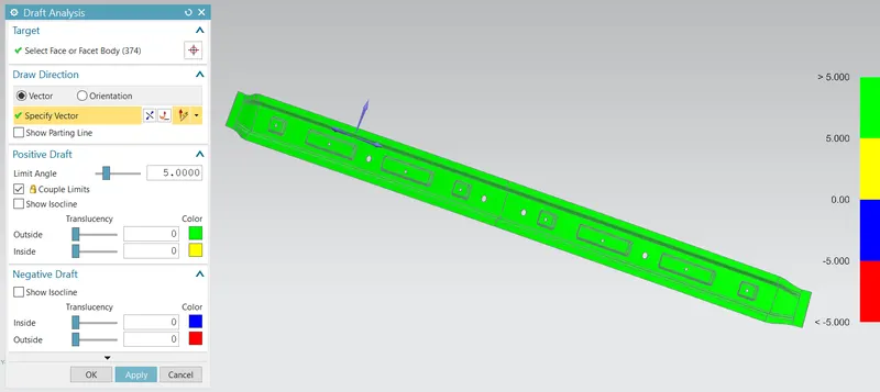
BOW ROOF 2
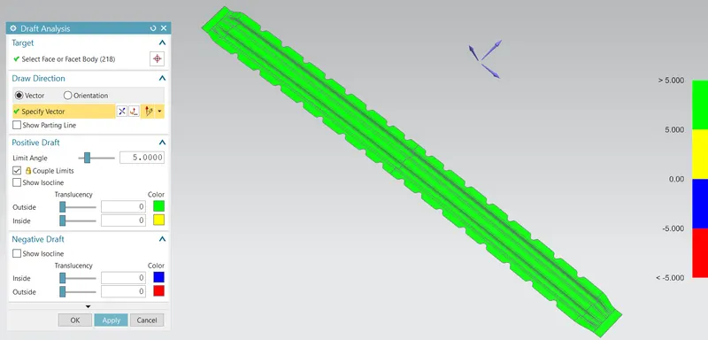
CENTER BOW ROOF
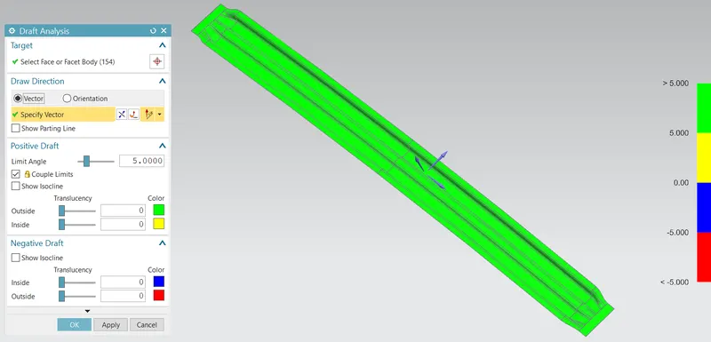
BOW ROOF 3
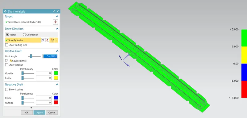
CENTER BOW REINFORCEMENT
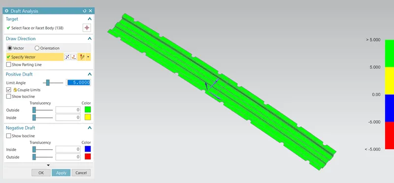
CONCLUSION
The Roof was created with all the required parameters and different Calculations were done for safety concerns. The design creation is done and the draft analysis is carried. From the calculation Heat distorsion is ok and in snow load calculation, we get NG as result.So we need to improve the surface for create the design sucessfully.