Roof Design
Aim - Create an ASSEMBLY by developing the essential flanges for the outer roof and creating the reinforcements.For the Given Roof styling
1. Roof Assembly
The conventional task of the roof panel is that of compartment shielding, passenger protection and connection of body sides, front and roof cross members. In case of roll over, compartment integrity is provided by the compartment frames, whilst the roof target is only to avoid the ejection of passengers, providing protection against hard local contact.
Correspondingly a wide selection of suitable materials are available: Steel, aluminium, thermosetting plastic sheet, glass. In case of steel grade FEP04, the usual thickness is in the range of 0.65 to .85 mm. In all cases, any roof panel material requires braces to prevent panel flexing and vertical waviness, commonly known as oil canning: for this purpose light steel bows are introduced, which are welded or riveted or screwed to the body side and bounded to roof panel by smooth flexible adhesives such as butyl mastic (in order to avoid sink marks on roof surface), mainly providing a damping effect.
Another task of roof bows is to support the interior roof liner which requires a number of fittings both in central and boundary areas to avoid deflections and vibrations. Fittings are usually plastic clips or velcro strips. Some roof liners, mostly on less expensive vehicles are bonded directly to roof panel.
2. Objective
- For the given Roof styling and master section, develop the essential flanges and reinforcements, provide appropriate dimension and check for Draft analysis and also submit section inertia analysis report on 0-Y section.
- Creation of roof ditch area the tool opening angle is only 3 to 5 degree.
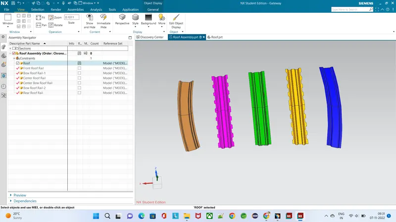
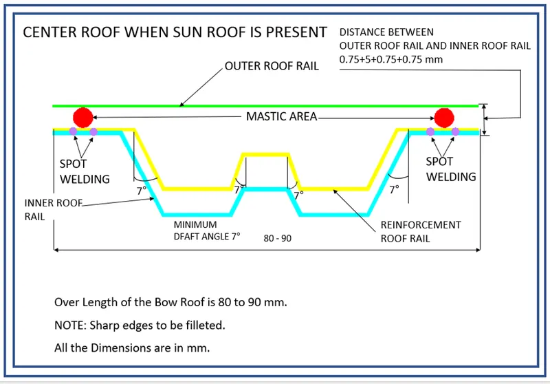
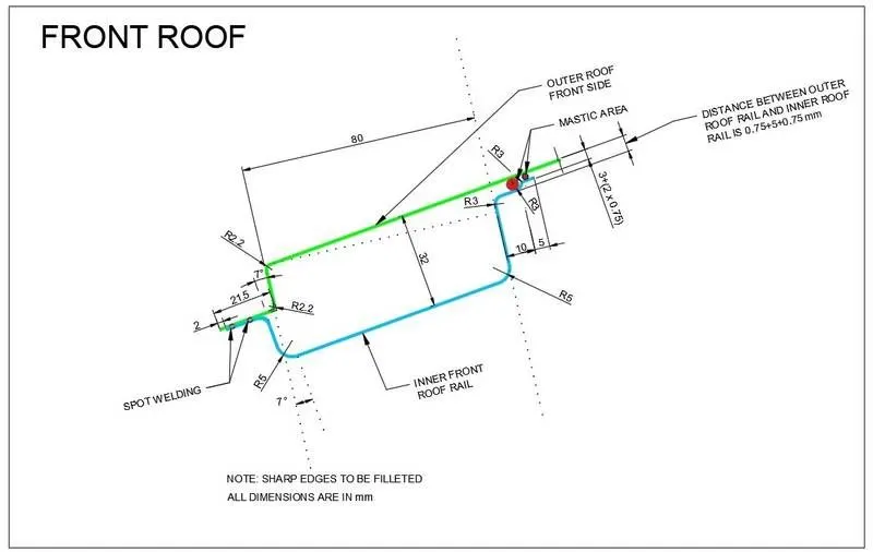
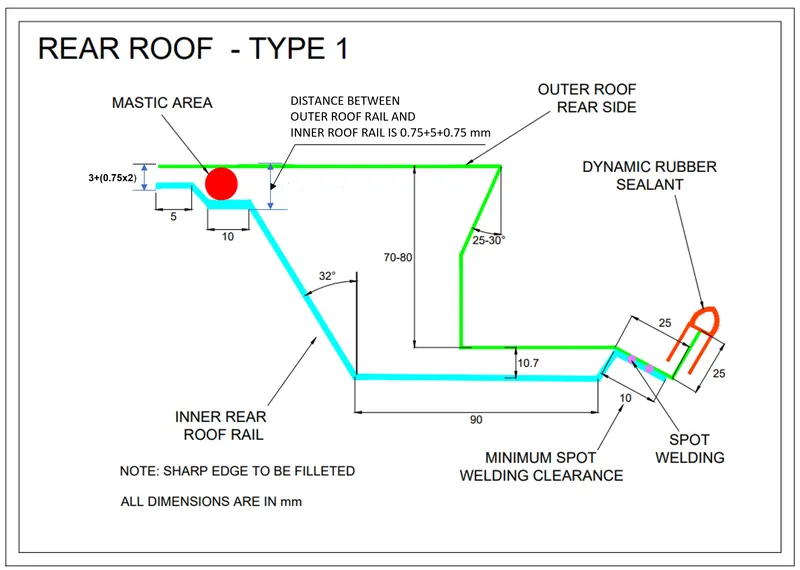
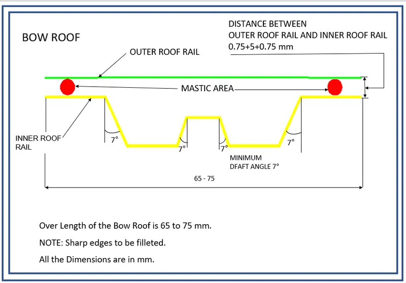
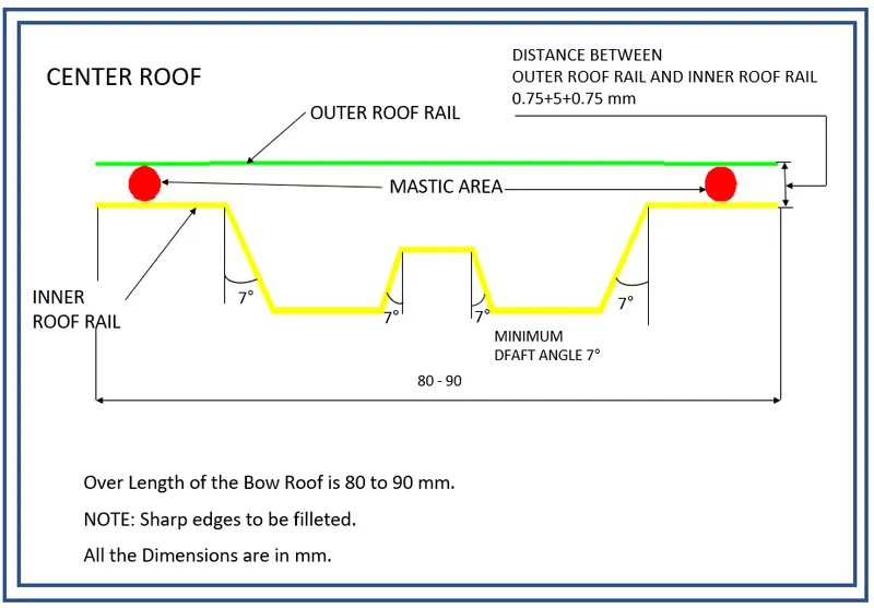
- Design and develop roof rails as per the given master sections.
- Perform section modulus study for the Master sections created for the Front roof rail, Rear roof rail, Bow Roof Rail and Rear Roof Rail.
- To do a curvature study on the roof and perform calculations to determine the position of the Bow-roofs.
- To perform Heat distortion criteria and Snow Load criteria tests on the designed roof and do optimization if necessary.
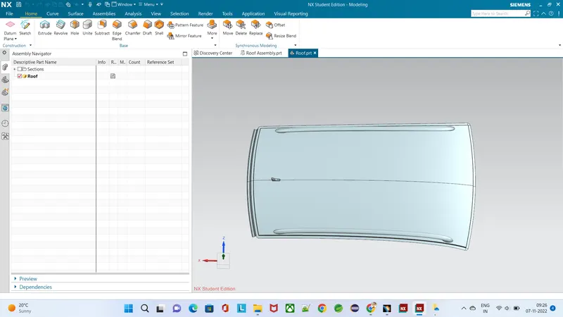
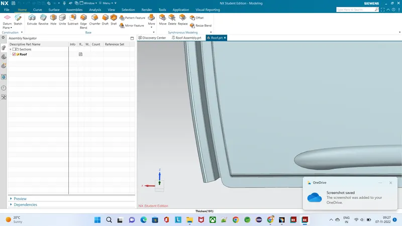
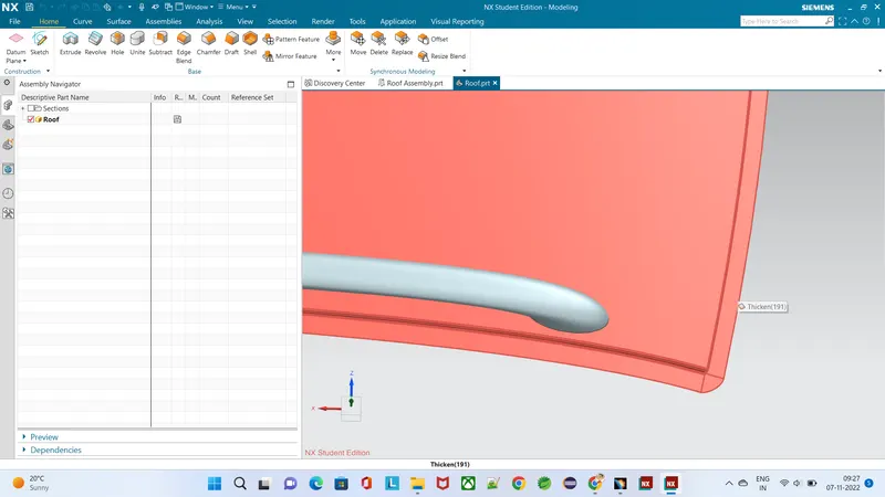
Thickness of roof = 0.65 mm
Draft angle = 3-5°
4. Design of Roof Rails:
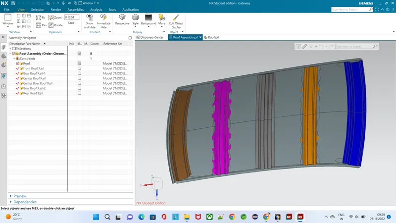
Roof rails are designed according to master sections provided.
Thickness of each roof rail = 0.65 mm
6. Draft Analysis of Roof and Roof Rails
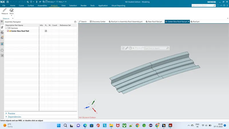
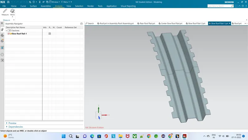
Draft analysis is carried out to obtain visual feedback on back draft condition of the part and an optimum die press direction is defined that maximises back draft. This analysis helps us to avoid die-lock situations, make decisions on an appropriate parting line, obtain suggestions on cutter sizing for machining and other purposes.
6.1 Draft Analysis of Roof:
6.2 Draft Analysis of Front Roof Rail:
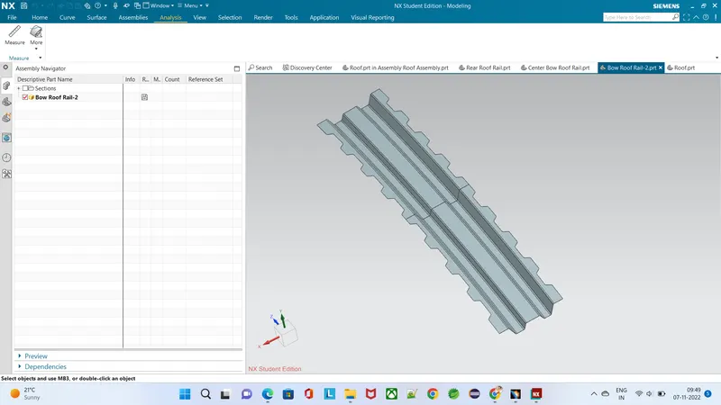
6.3 Draft Analysis of Bow Roof Rail-1:
6.4 Draft Analysis of Center Roof Rail:
6.5 Draft Analysis of Center Bow Roof Rail:
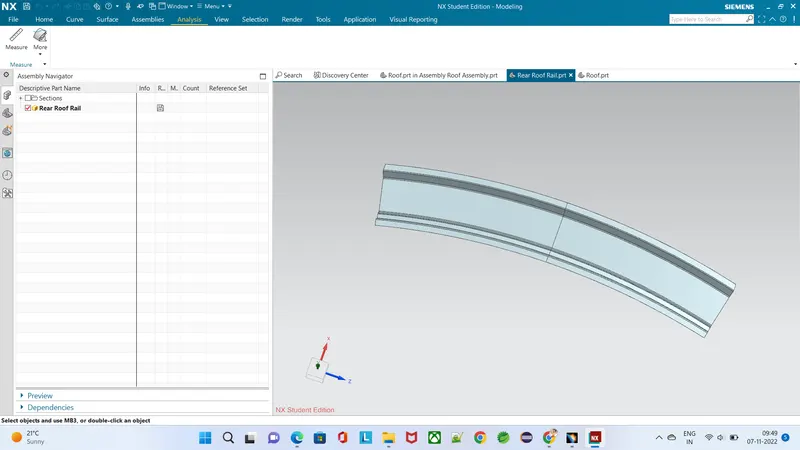
6.6 Draft Analysis of Rear Roof Rail:
7. Roof Specifications:
The delivery tests specified for roof assembly are static, dynamic and impact. The purpose of static testing is to verify that roof assembly exhibits no permanent deflection due to distributed load representing snow load and due to heat distortion.
7.1 Heat Distortion Criteria:
Heat distortion test is a type of static load test which plays an important role in maintaining roof strength. Heat distortion temperature is the temperature at which metal softens and deforms under a specified load. From Heat distortion criteria, roof strength can be enhanced by appropriate positioning of bow roof rails.
Bow – roof prediction Formula :
W = (1.73 x 10^-3 x L) + (1.85x10^-8 x (R^2)/t + 1.10 x 10^-3 x l) - 2.68
where,
L = Roof Length in X-Direction[mm](Roof dimension in 0-Y)
R = Roof curvature = 2(Rx*Ry)/(Rx+Ry)
Rx = X curvature
Ry = Y curvature
t = Roof plate thickness [mm]
l = Bow Roof Span [mm]
Judgement Condition : 2.7<W<3.5
From above results it can be observed that the designed roof passes Heat Distortion Criteria.
7.2 Snowed Criteria:
The snow load test is a type of static load test used to verify that roof assembly exhibits no permanent deflection due to a distributed load representing snow load: the distributed pressure applied is in the range 10-15 N/dmᶺ2.
Qr = [Iy x t2] / [α x s x [(Rx + Ry)/2]2 x 10-8]
Note: The Qr value given over here is correct. There was a typo error in the formula given in the video.
Where,
α = My x Lx2 x 10-12 , My = Y(Ly-Y)
t = Roof plate thickness [mm]
Ly = Distance between the front and rear roof Rails on the Vehicle along with 0Y[mm]
Length of Roof panel with the center point between Roof rail Front /Rear as the front and rear reference point.
Lx = Distance between the Left and Right end of the roof on the Roof BOW [mm]
The width of the roof panel is exposed on the surface.
Y = Distance front Front Roof Rail to Roof BOW[mm]
s = Distance for which Roof BOW bears divided load [mm]
s = L1/2 + L2/2
Iy = Geometrical moment of inertia of Roof BOW (Y cross-section )[mm4]
Rx = Lateral direction curvature radius of roof panel Y cross-section on Roof BOW [mm]
Roof panel curvature Radius of the Length Lx in Front view
Ry = Longitudinal Direction curvature radius of the Roof panel X cross-section on Roof BOW [mm]
Roof panel X curvature radius of length s in Side view
Judgment condition
Qr ≥ 3.1
250 ≤ s ≤ 380
From the above results it can be seen that the designed roof passes Snowed Criteria.
Conclusion -
We were successfully able to design the roof with all the roof rails for better support and strength. We designed it so as to satisfy the norms and regulations by calculating the heat distortion criteria and the snow load critera. While doing this we also understood about the methodology behind designing the roof of the car and what all we take into consideration while designing so.