Roof Design
INTRODUCTION:
The roof of a car or other vehicle is the top part of it, which protects passengers or goods from the weather. The roof also protects the passenger from any injury when the car gets crashed or is rolled over or something heavy falls on the roof.
DESIGN CONSIDERATION:
1).Visibility criteria
2).Head clearance
3).Curvature study
4).Hear distortion and snow load criteria
5).Draft analysis.
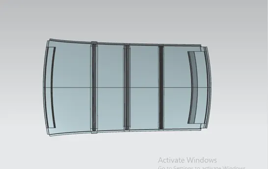
1.Front Roof Rail:
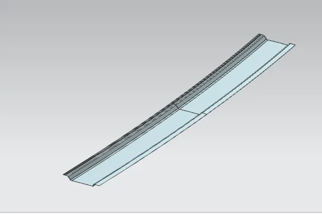
The front roof rail is located on the front of the roof where the wind shield joins with the roof. The visibility criteria and the head room clearance of the passenger are taken into consideration for the bottom flange. One end of the rail is joined using spot welding while the other end is joined with the roof using mastic sealants for increased strength.
- Bow roof 1:
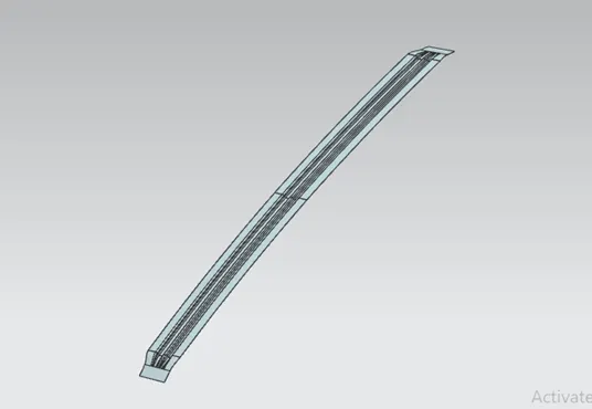
Bow roof is an additional stiffening member for the roof to increase the strength and so that it can satisfy the norms. Both the ends are joined together using mastic sealants to increase strength and also since this would not affect the styling of the roof.
- Center Roof Rail:
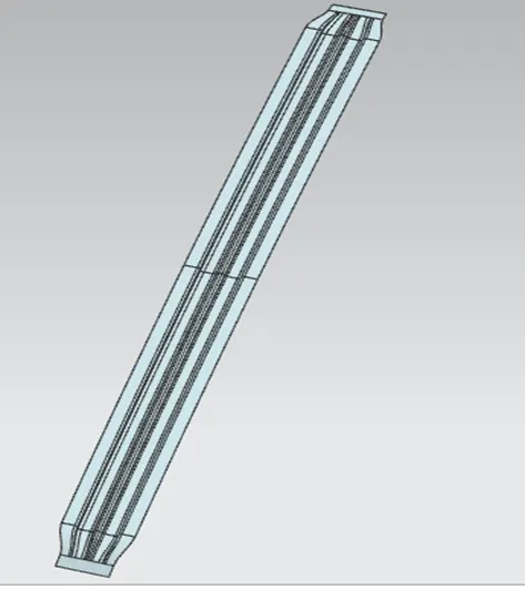
Centre Roof rail or the reinforcement center is located at the center of the roof. The cross section of this is more since it needs to provide more strength to the roof. Here both are ends are joined together using mastic sealants.
4.Bow roof 2:
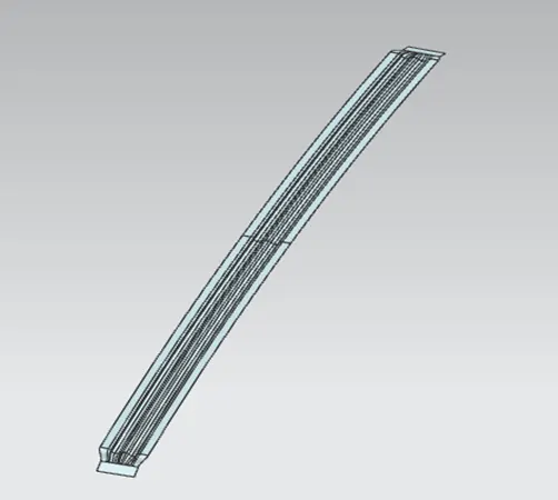
This bow roof also has the same purpose as that of the first one. This one is located between the center bow roof and rear roof rail.
- Rear Roof Rail:
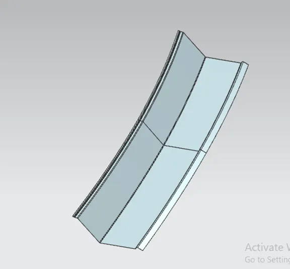
This roof rail joins with the back door and the roof. Inputs from the backdoor are taken into consideration for designing this roof rail.
Here one end is joined using spot welding while the other end is joined using mastic sealants.
CALCULATION
Heat Distortion Curvature Study:
This study is used to find out and predict the heat distortion temperature at where the material starts to soften when exposed to a fixed load. So in order to avoid bending or damage of the roof based on this calculation we will decide the position on the roof bows on the roof.
FORMULA:
W = [1.73 x 10^ (-3) x L] + [1.85 x 10^(-8) x (R^2)/t] + [ 1.10x10^(-3) x l] - 2.68
Judgment Condition: OK< 2.7> 3.1
Where,
L = Roof Length in X-Direction [mm](Roof dimension in 0-Y)
R = Roof curvature
R = 2(Rx*Ry)/ (Rx+Ry)
Rx = X curvature
Ry = Y curvature
t = Roof plate thickness [mm]
l = Bow Roof Span [mm]
Result:
|
Bow position |
Rx |
Ry |
R |
l |
L |
t |
RSQAURE |
W |
Ok/ No |
|
FR and 1st |
5715.38 |
2832.38 |
3786.95 |
480.52 |
2018.73 |
0.75 |
1.43*10^7 |
1.69 |
OK |
|
1st BOW and CTR |
7543.98 |
6786.46 |
7110.73 |
325.78 |
2018.73 |
0.75 |
5.05*10^7 |
2.1 |
OK |
|
CTR and 2nd BOW |
9995.16 |
10412.22 |
10192.39 |
354.19 |
2018.73 |
0.75 |
1.038*10^8 |
1.2 |
OK |
|
2nd BOW and RR |
6946.21 |
4378.23 |
5370.68 |
347.36 |
2018.73 |
0.75 |
2.88*10^7 |
1.9 |
OK |
.
Snow Load Criteria:
We predict the snow load in this of the roof bows and then place and change the design of the load accordingly to satisfy the condition.
Formula:
Qr =[Iy x t2] / [α x s x [(Rx + Ry)/2]2 x 10-8]
Where,
α = My x Lx2 x 10-12 , My = Y(Ly-Y)
Judgment condition = Qr ≥ 3.1
250 ≤ s ≤ 380
t = Roof plate thickness [mm]
Ly = Distance between the front and rear roof Rails on the Vehicle along with 0Y[mm]
Length of Roof panel with the center point between Roof rails Front /Rear as the reference point of the front and the rear.
Lx= Distance between the Left and Right end of the roof on the Roof BOW [mm]
Width of the roof panel exposed on the surface.
Y = Distance front Front Roof Rail to Roof BOW [mm]
s= Distance for which Roof BOW bears divided load [mm]
s = L1/2 + L2/2
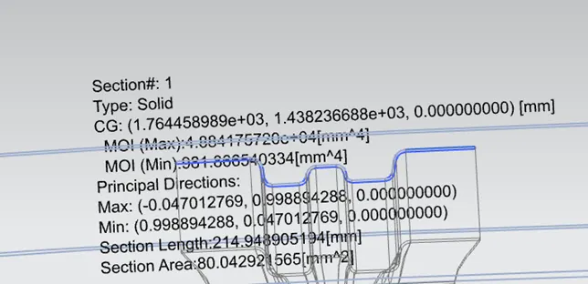
Iy = Geometrical moment of inertia of Roof BOW (Y cross-section) [mm4]
Rx = Lateral direction curvature radius of roof panel Y cross-section on Roof BOW [mm]
Roof panel curvature Radius of the Length Lx in Front view
Ry = Longitudinal Direction curvature radius of the Roof panel X cross-section on Roof BOW [mm]
Moment of inertia of BOW 1:
Moment of inertia of bow 2:
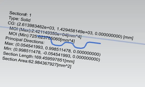
MODIFIED MOI OF BOW 2:
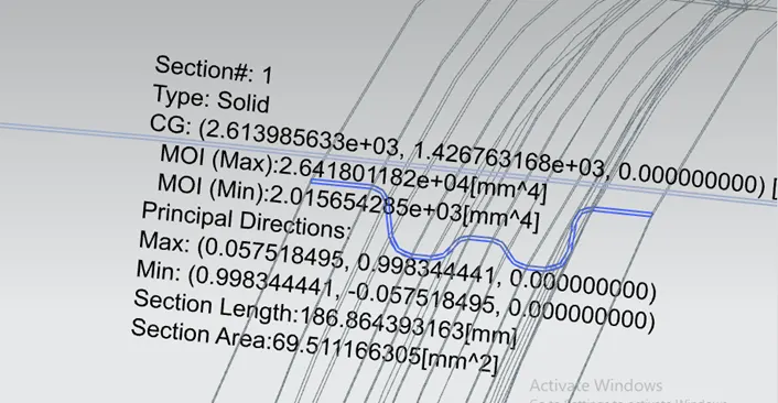
If we use unmodified moment of inertia for bow roof rail 2, it won’t satisfied the snow load criteria condition. That’s why we offset the bottom most two surface for 5 mm. the minimum moment of inertia value is get to increase after it will satisfy the conditions.
MOI OF CENTER ROOF RAIL:
Result-
|
Bow position |
Iy |
α |
Lx |
Ly |
Y |
S |
Rx |
Ry |
t |
Qr |
RESULT |
|
FR and 1st bow |
985.39 |
1.007 |
1134.80 |
2018.9 |
582.35 |
500 |
4361.69 |
2860.9 |
0.75 |
8.3 |
OK |
|
1st bow and CTR |
1.019*10^3 |
1.199 |
1085.20 |
2018.9 |
998.02 |
424 |
3803.24 |
3803.2 |
0.75 |
4.05 |
OK |
|
CTR and 2nd bow |
2.0156*10^3 |
0.948 |
1062.45 |
2018.9 |
1432.17 |
465.2 |
4256.55 |
10874.5 |
0.75 |
4.529 |
OK |
So all the values satisfied the snow load criteria so we won’t need to provide the extra emboss on the surfaces.
In the table center to 2nd bow roof rail I took modified value in this condition. I gave extra 5mm to the offset surface between head clearance value. Then it was satisfied our snow load criteria.
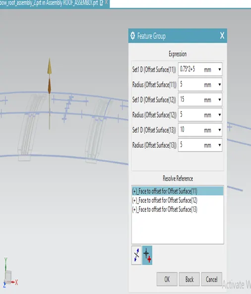
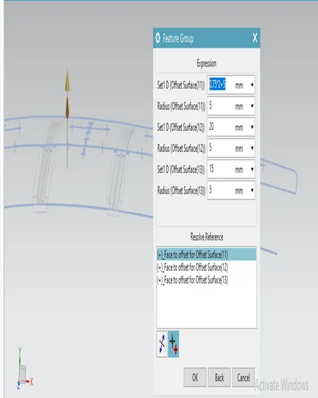 OFFSET VALUE FOR BOW ROOF 2 MODIFIED OFFSET VALUE BOW ROOF 2
DRAFT ANALYSIS:
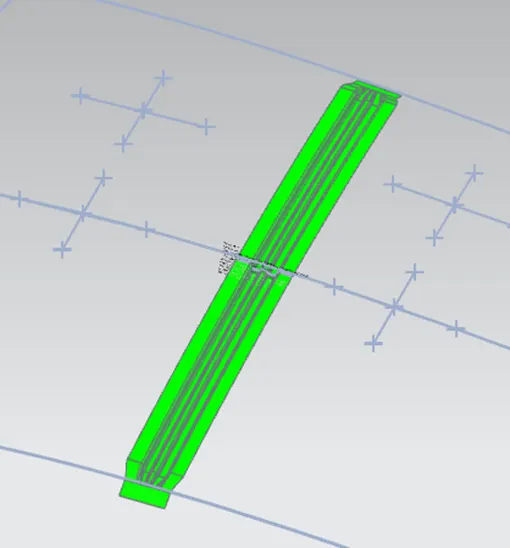
The draft analysis limiting angle is 7 degree, but we can maintain draft angle is 7-10 degree. Green colour indicates positive draft and red colour indicates negative draft.
Bow roof rail 1 :
Bow roof rail 2:
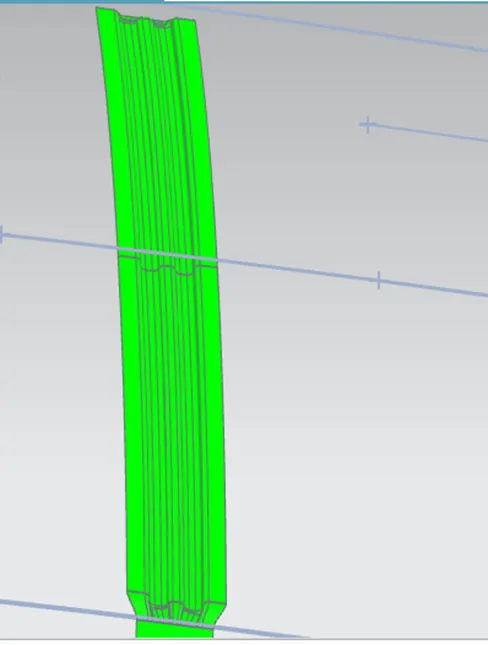
Center roof rail:
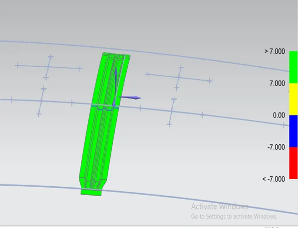
Rear roof rail:
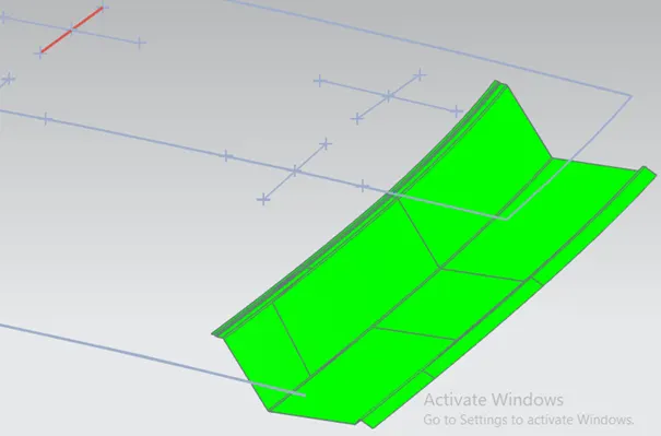
Roof outer panel:
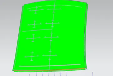
Conclusion:
We designed roof as per under the design norms and also satisfied the criteria. Provide strength to the roof by developing multiple bow roof and center roof rails, we develop the rails as per the region condition. Roof won’t deform in climate changes. when the car roll over it will help to protect the passengers.