Roof Design
CAR ROOF :
The component of an automobile that is located above the passenger compartment and shields the occupants from the sun, wind, rain, and other environmental factors is called the car top or roof.
Numerous modifications to the car roof emerged over time. Among them are
- Sunroofs
- Convertible roofs
- Hardtops
- Vinyl roofs
- Solar roofs
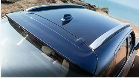 Car top or roof
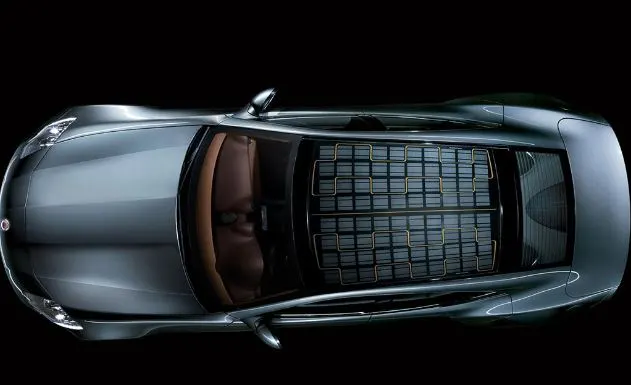
Solar Roof
Design specifications:
The styling team provides the hardtop roof's styling surface for development. Typically, the car roof is made up of an exterior panel and its supports. These reinforces are,
- Roof
- Front roof rail
- Bow roof
- Centre roof and
- Rear roof rail
The design of an automotive roof must adhere to specific engineering criteria. These standards are the result of trial and error over many years to lower production costs, increase safety, and waste less material. Depending on the local conditions, customs, laws, and regulations, these criteria may change from place to place. Headroom clearance, driving vision, heat distortion criteria, and snow load criteria are frequently taken into account while designing roofs. Common guidelines for automobile roof design said that the blending should be no less than 3+t (t-thickness of the portion) and that the draft angle should be at least 7º.
Master section:
Master sections are basic (2D) outlines obtained at specific points in a model, or they are the intersection of a 3D model with a reference plane so that the outline can be studied in a 2D view. To communicate the functional needs of the commodity to the design engineer, OEMs and the automotive industry frequently utilize these master sections. It provides the dimensions that should be taken into account while creating a specific part or component, including height, breadth, length, radius, and clearance.
1. Roof:
The entire automobile roof is composed of sheet metal it is called BIW. The roof outer panel serves as both the external covering for the passenger or occupant compartment from the rear door to the wind shield and as an aesthetic component of the roof.
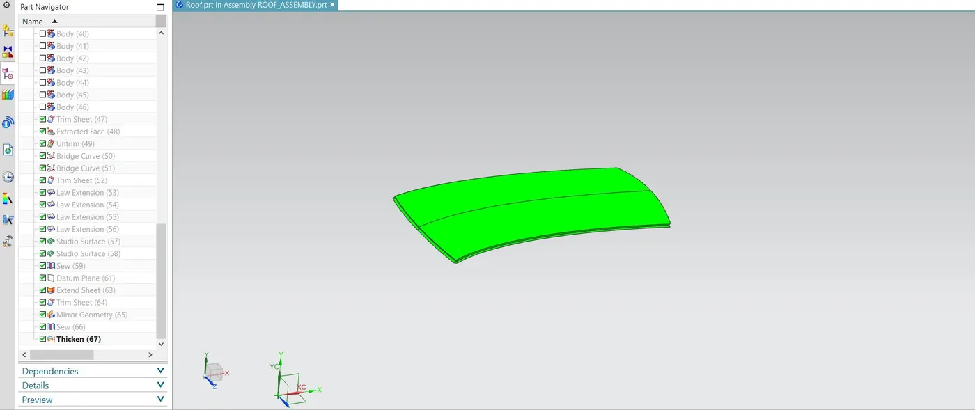
- To begin developing the roof, the specified styling surface is extracted; it is then saved unaltered as an input surface for later use.
- After filling in any gaps and holes, the extracted surface is untrimmed, and the trim command is used to eliminate any excess surfaces that extend beyond the style surface's borders.
- The law extensions of flange are constructed at the front side with respect to the master section of the front roof rail.
- After that, edge blends were sewn onto its corners and edges using these extensions.
- Following the creation of the front flange, the ditch region was made utilizing the same edge blends, sews, and law extensions in relation to the front flange's measurements.
- In order to create a smoother corner, the space between the front flange and the ditch region is filled in using curve mesh commands and bride curves.
- Then, in relation to the master portion of the rear roof rail, the outer panel's rear flange was made using the earlier procedures; in this case, the corners were trimmed off but left undisturbed to provide some relief.
- Next, in order to prevent gaps when mirroring it, the sheet is expanded at the 0y portion and trimmed using the xz plane.
- After the outer panel is finished, it is sewn together and mirrored around the corresponding plane.
- In order to create a solid portion, the entire outer panel surface was thickened to 0.75 mm, and its jagged edges were blended.
2. Front Roof Rail:
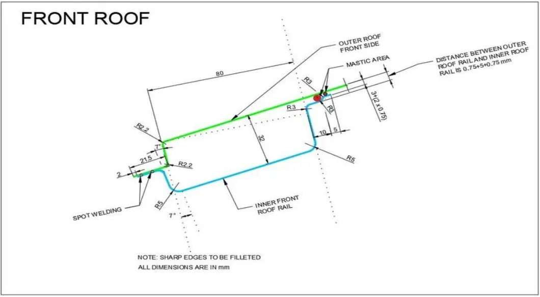
- According to engineering standards, these are all the minimal values that must be kept in the roof outer panel design.
- To construct the ditch area at the sides of the outer panel, some of these measurements are also taken into consideration.
- The driving field of view and the occupants' headroom are specified in the following front roof master parts.
- Spot welding at the front flange area will be used to assemble the front roof rail with the outer roof panel. Therefore, the front roof flange offset from the outer panel front flange is 0.75+0.2+0.75mm.
- Consequently, the front roof's offset for the emboss is 32 mm from the roof outer panel, and its length should be 80 mm from the front flange
- The distance between the emboss end and the rear flange of the front roof is 15 mm, with two divisions: 10 mm and 5 mm.
- The offsets of (0.75+5+0.75mm) and (3+2*0.75mm) on this flange from the outer panel are to allow for the expansion of mastic sealant during assembly with the outer panel.
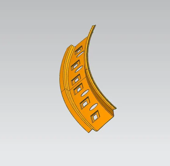
- Using the wave geometry linker command, the reference surfaces for the front roof are extracted from the roof outer panel.
- Additionally, their linkages were severed and retained as the front roof rail's input surfaces.
- These surfaces are used to offset the front roof rail creation to the necessary dimensions in accordance with the front roof rail master section.
- Following the offsets, the necessary curve was offset to the necessary positions using the "offset curve in face" command in order to eliminate the undesirable surfaces.
- The "trim sheet" command was used to eliminate the undesired surfaces, then law extensions were made to join the surfaces at various heights.
- Using the "trim and extend" command, the overlapping surfaces were now trimmed to create corners, which were then blended.
- Next, using the 'emboss' command, some embosses were made to strengthen the front roof rail.
- Following completion of the surface creations, the sheet is extended and trimmed at the 0y region.
- Lastly, the front roof rail surface is mirrored around the xz plane. It is then sewn together using the "sew" command and its sharp edges are merged using the "thicken" command to produce a solid portion.
3.Bow roof
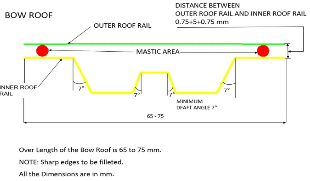
- This master section states that the bow roof's overall width should be between 65 and 75 mm, and that each embossed area should have a minimum of 7º of positive draft in relation to the tooling direction.
- The bow roof should be positioned in the flatter area rather than the curved area of the roof, with the offset of the outer flange being 0.75+5+0.75mm from the outer panel of the roof. Every portion of the bow roof has the same set of specifications.
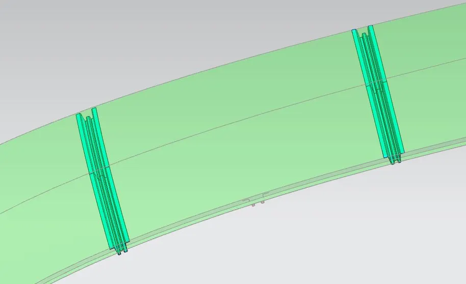
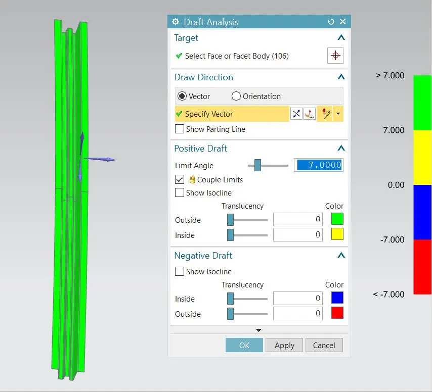
- Using the wave geometry linker command, the reference surfaces for the bow roof are extracted from the roof outer panel. Additionally, their linkages were severed and retained as the bow roof's input surfaces.
- These surfaces are used to offset it to the necessary dimensions in accordance with the bow roof master section, which is the first step in creating the bow roof.
- Following the offsets, the necessary curve was offset to the necessary positions using the "offset curve in face" command in order to eliminate the undesirable surfaces.
- The "through curve" command was used to link the surfaces of varying heights after the undesired surfaces were eliminated with the "trim sheet" command.
- The "sew" command is now used to stitch these surfaces together, and the "edge blend" command is used to merge their corners.
- Next, by projecting the sketch made on the plane normal to the surface to the surface and chopping off the undesirable areas, mastic zones were made at the outer flanges of the bow roof.
- Following completion of the surface creations, the sheet is extended and trimmed at the 0y region.
- Lastly, the bow roof surface is mirrored around the xz plane. It is then sewn together using the "sew" command and its sharp edges are merged using the "thicken" command to produce a solid portion.
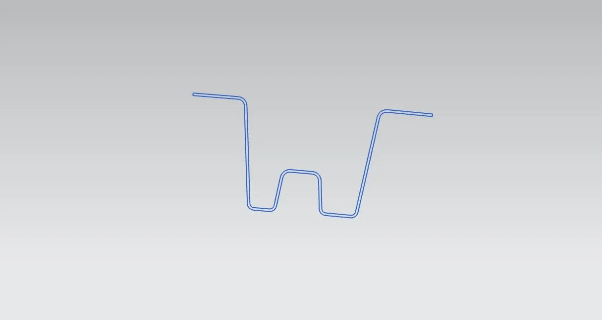
- Using the Datum plane and intersection curves, the bow roof rail's master section was constructed.
4.Center roof:
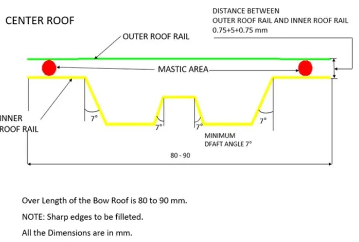
- The overall width of the center roof should be between 80 and 90 mm, and each embosse should have at least 7º of positive draft in relation to the tooling direction, according to this master section.
- Then, 0.75+5+0.75 mm is the offset of the center roof outer flanges below the roof outer panel. The location of the center roof is where the B-pillar joins the roof.
- In order to link and produce the center roof, the surface is offset and created utilizing law extension.
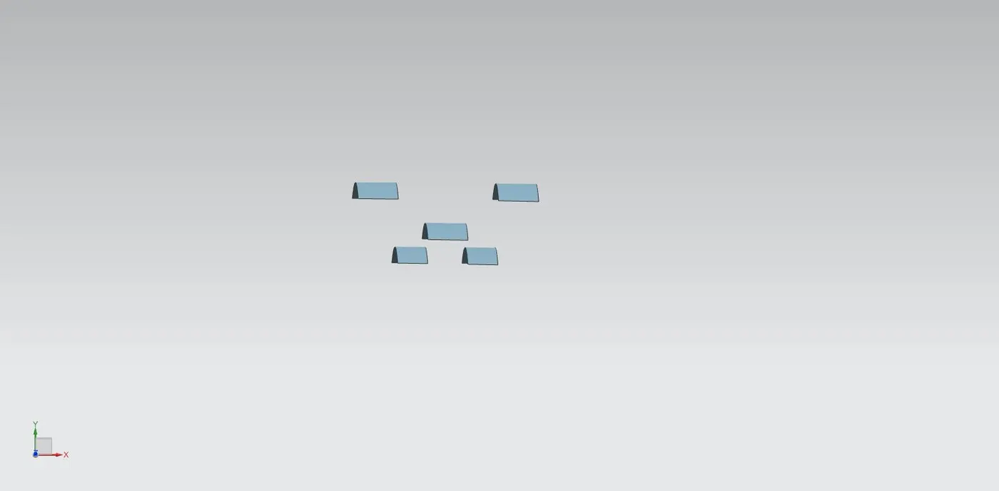
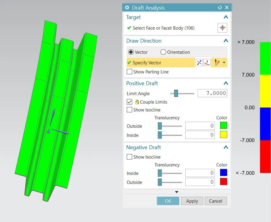
- Using the wave geometry linker command, the reference surfaces for the center roof rail are extracted from the roof outer panel. Additionally, their linkages were severed and retained as the center roof rail's input surfaces.
- These surfaces are used to offset it to the necessary dimensions in accordance with the center roof rail master section, which is the first step in creating the center roof rail.
- Following the offsets, the necessary curve was offset to the necessary positions using the "offset curve in face" command in order to eliminate the undesirable surfaces.
- The "through curve" command was used to link the surfaces of varying heights after the undesired surfaces were eliminated with the "trim sheet" command.
- These surfaces are now joined together using the "sew" command, and the "edge blend" command is used to blend the corners.
- Next, using the curves produced by the "curve on surface" command, mastic regions were made at the outside flanges of the bow roof. The undesired portions were then trimmed off with the use of these curves.
- Following completion of the surface creations, the sheet is extended and trimmed at the 0y region.
- Lastly, the bow roof surface is mirrored around the xz plane. It is then sewn together using the "sew" command and its sharp edges are merged using the "thicken" command to produce a solid portion.
5.Rear Roof:
The dimensions for the rear flange and roof rail of the outer roof panel are provided in this master part.
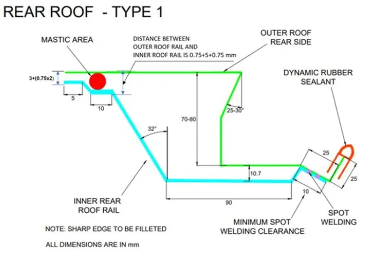
- To allow for back door motions, the outer roof panel rear flange should have a negative flange with a 25 to 30 degree draft.
- The rear flange's overall height must be between 70 and 80 mm, and the outermost flange's parameters for spot welds and rear door location should thereafter be met.
- The rear roof rail's characteristics are as follows: its width is 90mm, its offset is 10.7mm for the center emboss, and its offsets for the front and rear flanges are (3+0.75*2mm & 0.75+5+0.75mm). Subsequently, 32º is the draft angle for the emboss connecting the front flange.
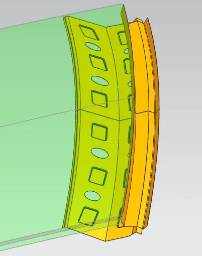
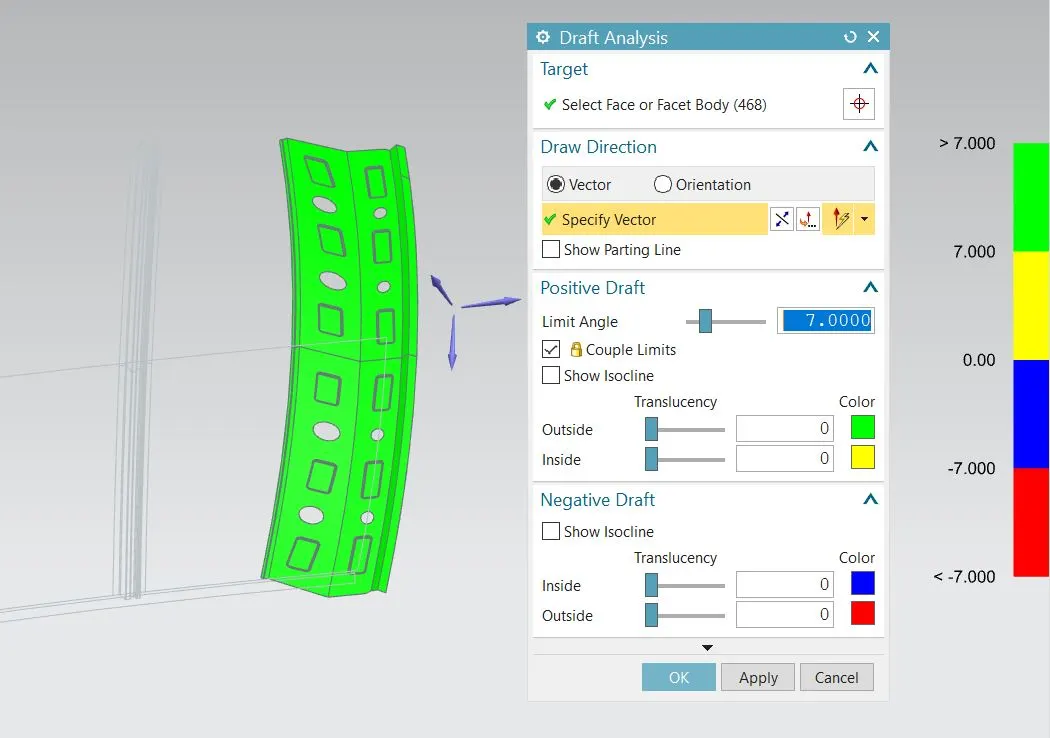
- Using the wave geometry linker command, the reference surfaces for the rear roof are extracted from the roof outer panel. Additionally, their linkages were severed and retained as the rear roof rail's input surfaces.
- These surfaces are used to offset the rear roof rail creation to the necessary dimensions in accordance with the rear roof rail master section.
- Following the offsets, the necessary curve was offset to the necessary positions using the "offset curve in face" command in order to eliminate the undesirable surfaces.
- The "trim sheet" command was used to eliminate the undesired surfaces, then law extensions were made to join the surfaces at various heights.
- Using the "trim and extend" command, the overlapping surfaces were now trimmed to create corners, which were then blended using the "edge blend" command.
- Then, using the "emboss" command, some embosses were made to strengthen the rear roof rail.
Following completion of the surface creations, the sheet is extended and trimmed at the 0y region. - Lastly, the rear roof rail surface is mirrored around the xz plane. It is then sewn together using the "sew" command and its sharp edges are merged using the "thicken" command to produce a solid portion.
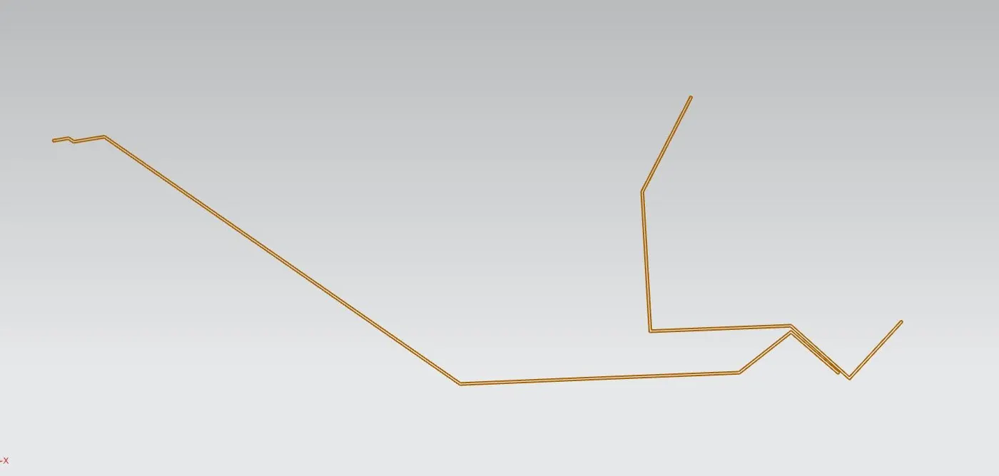
Master section for the Rear roof
Heat distortion:
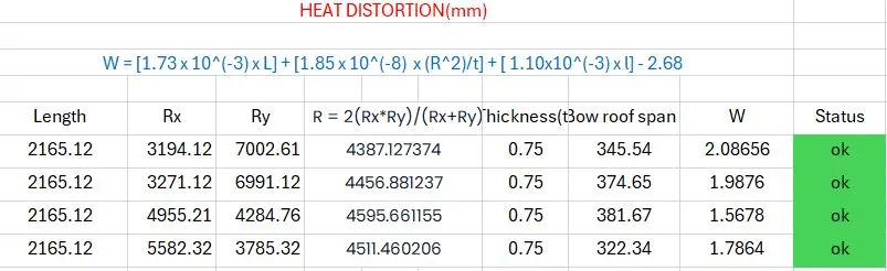
The temperature at which a metal softens and distorts under a given stress is known as heat distortion. The purpose of this study is to evaluate the roof's capacity to tolerate high temperatures in relation to the placement of reinforcements, which helps to strengthen the structure.
The heat distortion criteria of a roof by utilizing the subsequent formula:
W = [1.73 x 10^ (-3) x L] + [1.85 x 10^ (-8) x (R^2)/t] + [ 1.10x10^ (-3) x l] - 2.68
Were,
L = Roof Length in X-Direction[mm](Roof dimension in 0-Y)
R = Roof curvature
R = 2(Rx*Ry)/(Rx+Ry)
Rx = X curvature
Ry = Y curvature
t = Roof plate thickness [mm]
l = Bow Roof Span [mm]
Calculation: