Roof Design
ROOF DESIGN
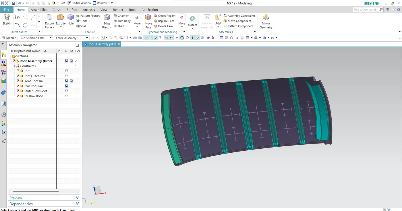
Roof is not a single element, it consists of Front roof rail, Rear Roof Rail, Bow Roof Rail, Centre Roof Rail. These Bow Roofs are placed in the most flat area of the Panel. Rear Roof Rail joins with the Back door and Body side outer. Front Roof Rail joins with the Wind shield glass and body side. Here are some reinforcements used in the Roof.
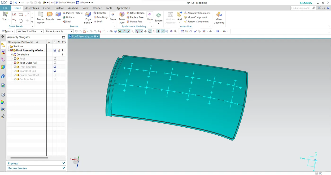
Outer Roof Rail:
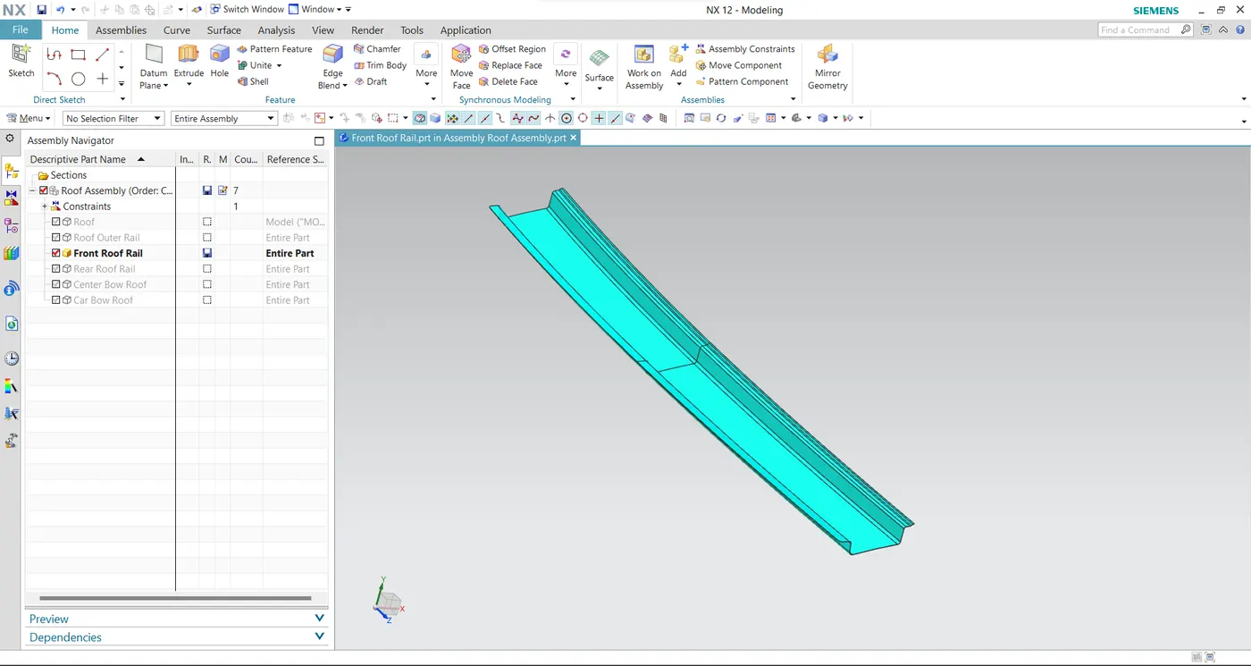
FRONT ROOF RAIL:
This will be a supporting room lamp for some cars. We need to consider the Visibility criteria line for designing Front roof rail.
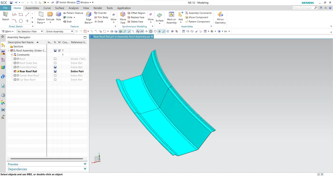
REAR ROOF RAIL:
Here we need to keep Head room clearance and rear-view criteria for designing. Back door will be mounted here.
BOW ROOF AND CENTER ROOF RAIL
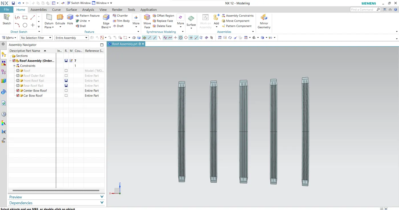
The bow roofs are given to improve the torsional stiffness and load bearing capacity of the roof structure. The number of bow roof present depends on the overall size of the roof. Presently I have added two bow roofs.
Centre roof rail helps in providing effective support to the flat area of the roof as it is more susceptible to failure under the action of load. generally, the centre roof rail is placed at the centre of the roof and is connected to the B-pillar structure. This helps in adding the strength to the roof during the roll- over test.
MANUFACTURING PROCESS:
Outside plate can be manufactured with the following process, first the open straight snips plate: first select applicable cold coiling specification, cold coiling is opened flat. Then according to production material specification, it will be opened after flat and be cut into the iron plate of corresponding size. Finally, the iron plate after shear is cleaned into iron filings. Then its trimmed and punched. Then its flanged and punched. Finally, after punching completed it is carried out to the operation of side folding.
Bar shaped assembly and ring-shaped component are processed by blanking, stamps out iron plate the outline blank of many roofs can’t rails, a ring-shaped component and a bar shaped assembly.
ROOF MASTIC:
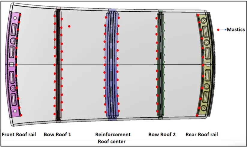
Mastic points are given on the various points of the roof to join the inner and outer panel of the roof. It also develops Good NVH for the car. Mastic sealants provides strength locally around 80mm of its point of application. So, we need order the points in a way that the it is evenly spread over the roof so that we can increase the strength of the roof. Mastic sealants applied on the roof will undergo hot bath where it expands and fills the 80mm of its surrounding.
SPOT WELD:
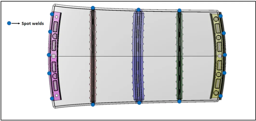
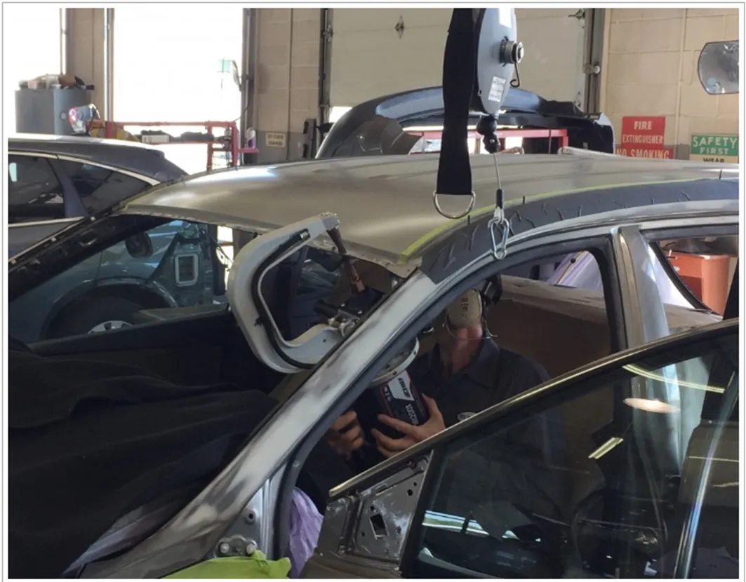
Spot welding is a type of electric resistance welding. It is also known as resistance spot welding. The process of spot welding is sheet metals are made into contact with each other and pressure is applied on specified points. So heat is generated from the resistance and weld is formed. Here below you can see the points to be spot welded in the roof panel. Spot welding prevents the original intended design of the component. Here below you can look at a real time view of spot welding on the roof.
ROOF CRUSH TEST:
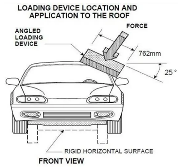
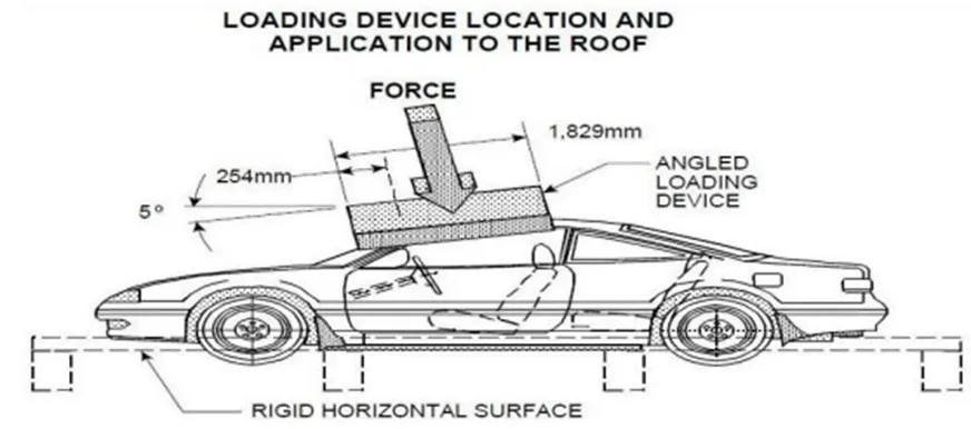
A rectangular block measuring 30 inches wide and 72 inches long is used to apply the load on car roof with 1.5 times the unloaded vehicle weight with different angle inclination to rectangular block. The moving distance of roof structure must be less than 127mm or 5 inches as per FMVSS standards.
ROOF CRUSH SYSTEM:
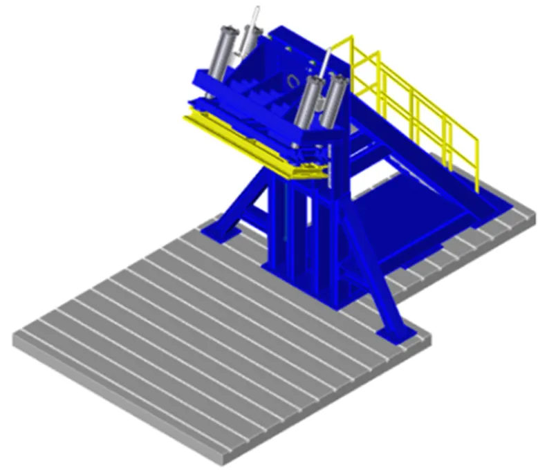
Here Crush test system is shown which is manufactured by MGA Corporation. It has an upright assembly and attached loading head that can be fixed at varied heights. Pitch angle can be varied by +5 to -5 degrees. But the roll angle is fixed to 25 Degree. Hydraulic actuators are used to control the movement of plate.
POSITIONING OF BOW ROOF:
Bow roofs are designed to give strength to the roof panel. It avoids the roof to bend due to snow load. Number of bow roofs needed are estimated with the design of the roof panel. if the length of the roof is large, we need more bow roof and if the roof panel is lesser in length, we need ideal number of bow roofs.
The positioning of Bow Roofs depends on the curvature of the roof panel. We add bow roof on flat region as bending is more possible here than the curved portion of the roof. Along with this we have Heat distortion criteria and Snow load Criteria for positioning the Bow roof.
HEAT DISTORTION CRITERIA:
The heat distortion test evaluates the ability of car roof to maintain its physical structure without deformation under elevated temperature conditions. Car roofs are exposed to sunlight at day time. Distortion of the car roof can create more susceptible to damage.
Heat Distortion Calculation:
W = [1.73 x 10^(-3) x L] + [1.85 x 10^(-8) x (R^2)/t] + [ 1.10x10^(-3) x l] - 2.68
Where,
L = Roof Length in X-Direction[mm](Roof dimension in 0-Y)
R = Roof curvature
R = 2(Rx*Ry)/(Rx+Ry)
Rx = X curvature
Ry = Y curvature
t = Roof plate thickness [mm]
l = Bow Roof Span [mm]
Judgment Condition
OK< 2.7
how we going to approach Heat distortion calculation in our design
- First of all, we have to select a plane on which we will do all the sketches and that plane should be parallel from your roof outer surface.
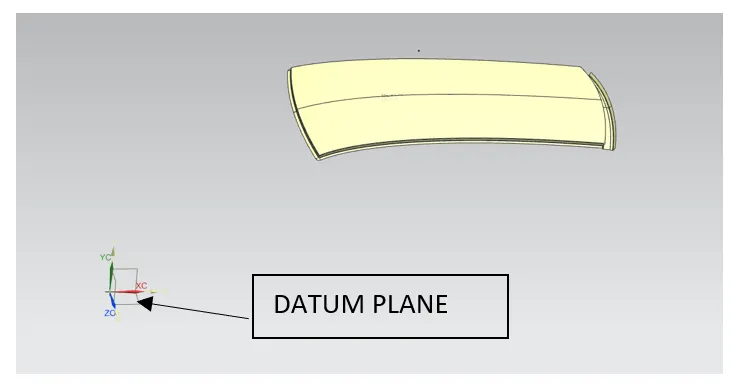
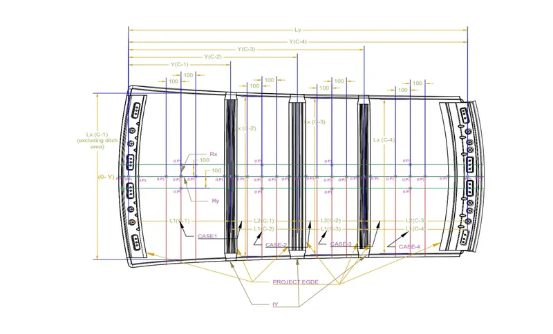
- After coming to the sketch, create 0-Y which will be the centre line of your roof, from that line you have to create an offset of 300mm which will be your 3-Y, Then 3-Y has to be offset 100mm- 100 mm respectively into up and down direction.
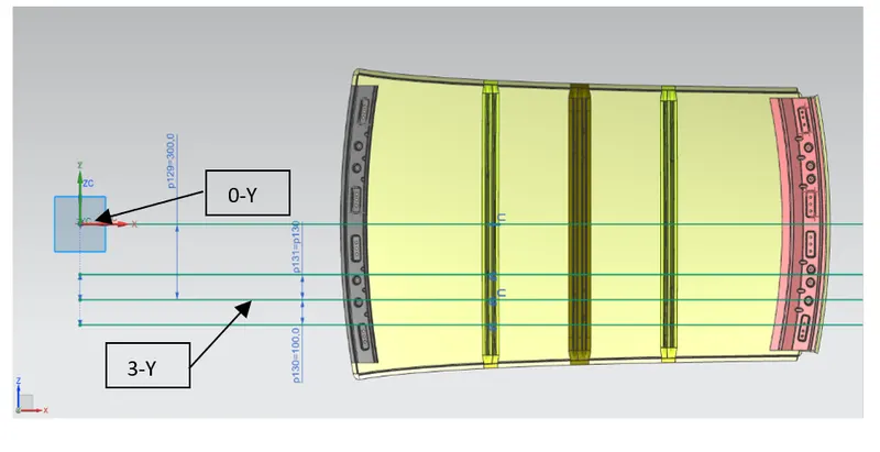
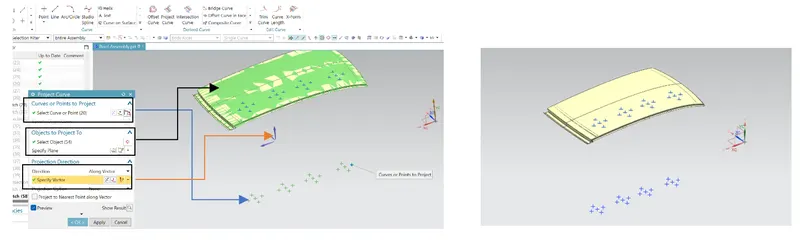
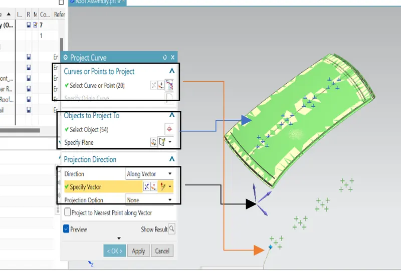
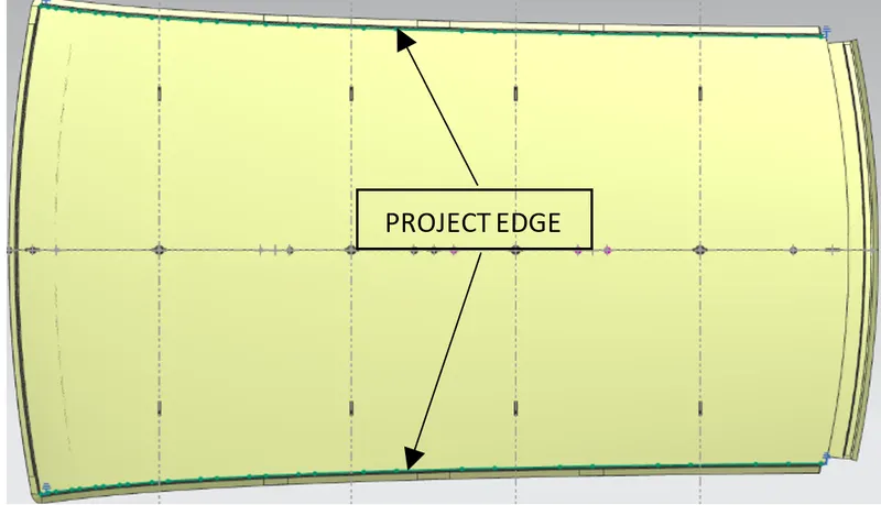
- The edges shown is to be projected (by project curve) in 2D Sketch
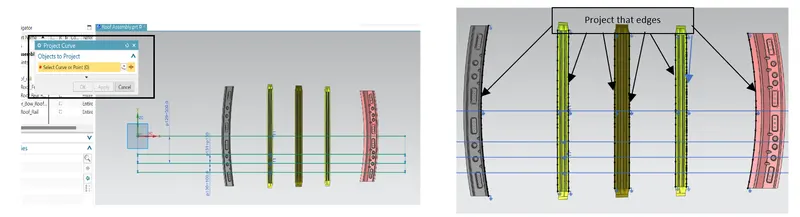
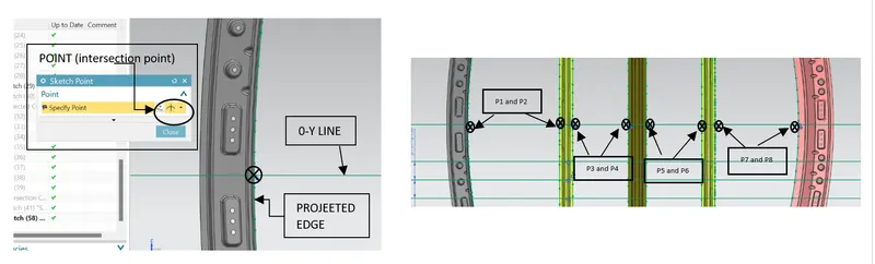
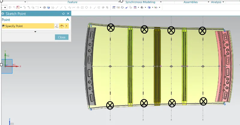
- hen the point of intersection of the points shown is to be created with the help of point command. To create the intersection point you have to select the intersection option and then select your project curve(pc) and 0-Y.
- Line has to be created with the help of the shown intersection point and with the help of the mid-point of that line, you have to create a vertical line.
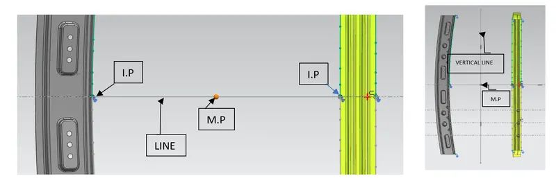
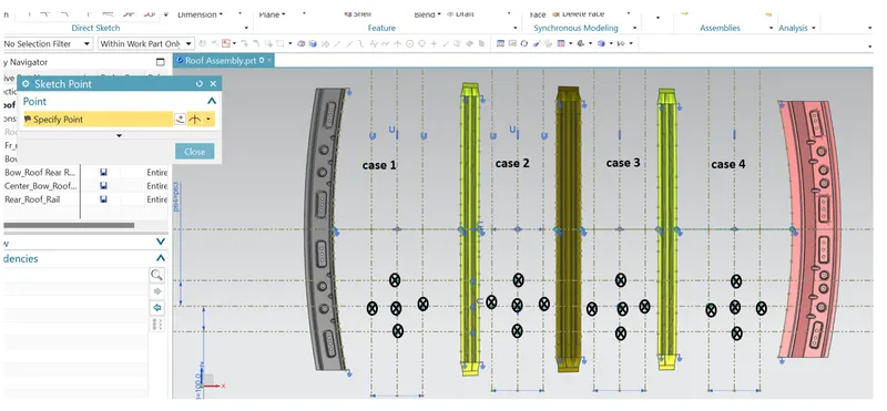
- That vertical line has to be offset 100mm-100mm relative right and left direction then create an intersection point at the points shown.
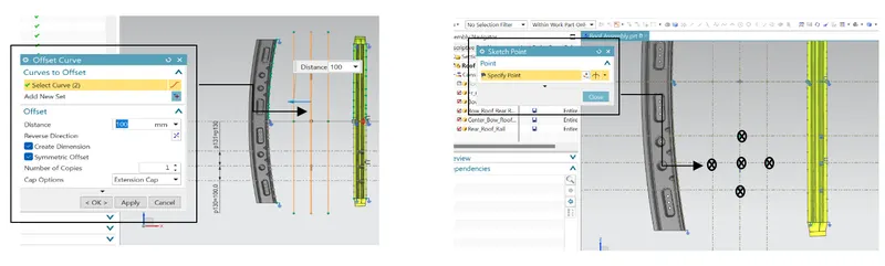
- Same process you have to repeat for further cases
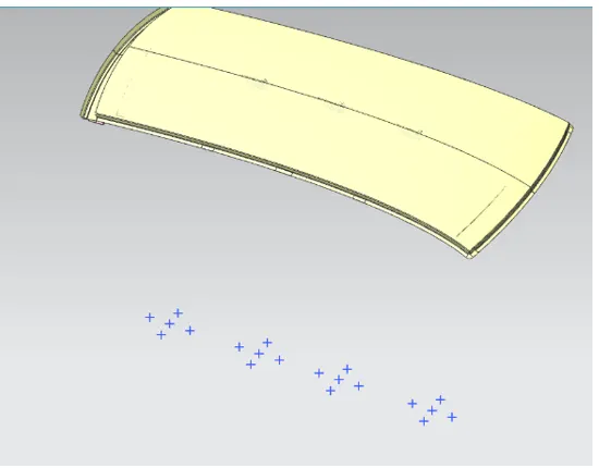
- Finish the sketch and project the points shown on the upper surface of the roof outer surface.
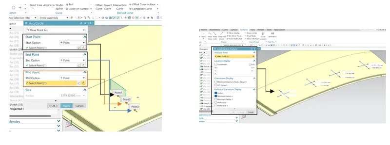
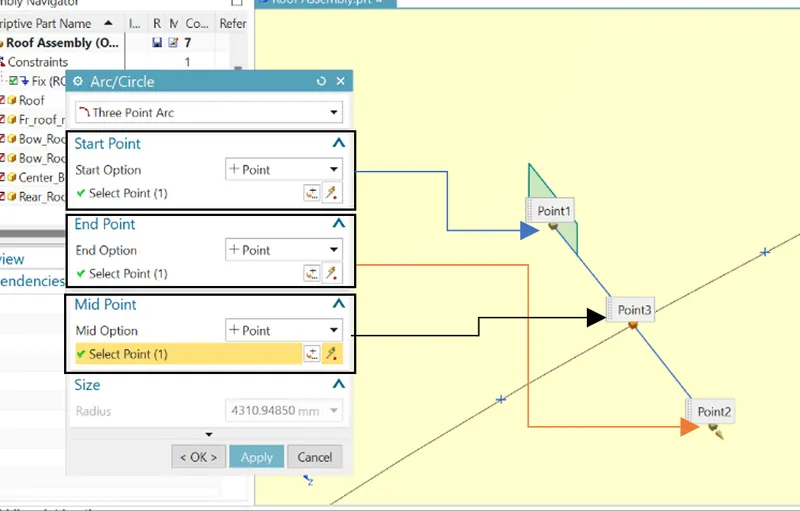
- Take the arc command and draw the arc with three-point option by specification start point, end point and mid-point. This operation you have to continue with all the horizontal and vertical points you petted. To display the radius of the created arc (Rx-Ry), the local radius command is used.
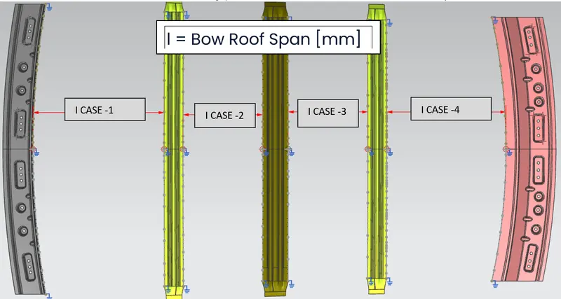
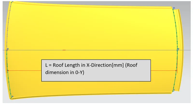
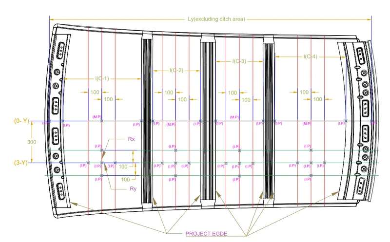
|
Bow–Roof Prediction for Heat Distortion |
|||||||||
|
Rail Distance |
L |
t |
Rx |
Ry |
R |
(R2/t) |
I |
W |
Result |
|
Front Roof rail to Bow Roof-1 |
2029.24 |
0.75 |
200.2867 |
203.4101 |
201.836 |
54317.199 |
173.8188 |
1.023 |
Pass |
|
Bow Roof-1 to Bow Roof-2 |
2029.24 |
0.75 |
200.5177 |
200.3255 |
200.422 |
53558.399 |
271.2526 |
1.130 |
Pass |
|
Bow Roof-2 to Centre Bow Roof |
2029.24 |
0.75 |
200.4005 |
200.0110 |
200.206 |
53443.022 |
243.6898 |
1.100 |
Pass |
|
Centre Bow Roof to Bow Roof-3 |
2029.24 |
0.75 |
200.0899 |
200.4949 |
200.292 |
53489.285 |
243.7582 |
1.100 |
Pass |
|
Bow Roof-3 to Bow Roof-4 |
2029.24 |
0.75 |
200.6264 |
200.3588 |
200.493 |
53596.329 |
270.8650 |
1.130 |
Pass |
|
Bow Roof-4 to |
2029.24 |
0.75 |
200.7945 |
200.6629 |
200.729 |
53722.670 |
212.0248 |
1.065 |
Pass |
SNOW LOAD CRITERIA :
Unlike in India there are countries with heavy snowfall. In Alaska it was recorded a record-breaking 78" in 24 hours in 1963. So, calculating and designing the roof of the car in such a way this snow does not cause serious damage to the car.
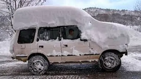
We can calculate with the below given formula.
Similar steps you have to repeat to find your R-x and R-y for snow load calculation but you have to do all these operations with zero 0-Y line.
- First of all, we have to create a plane on which we will do all the sketches and that plane should be parallel from your roof outer surface.
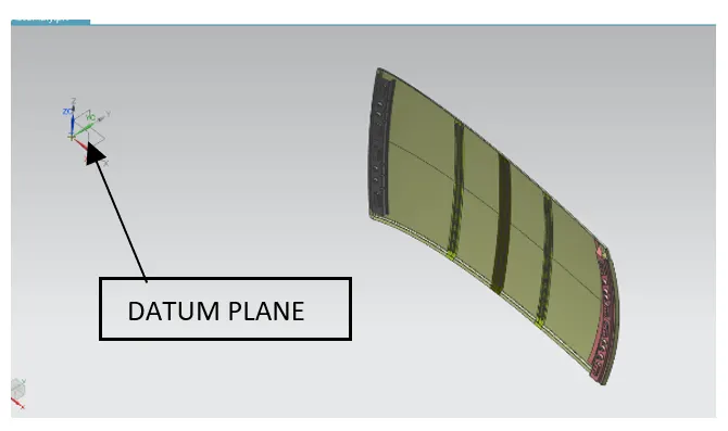
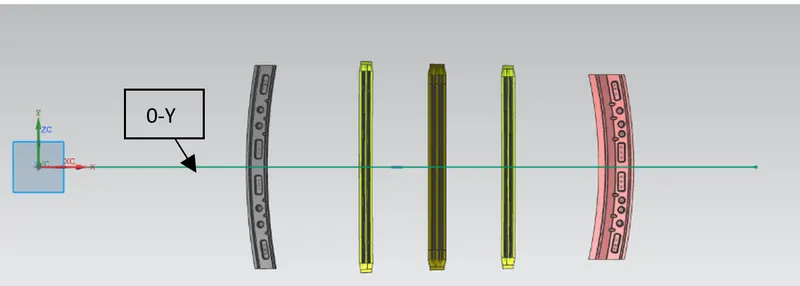
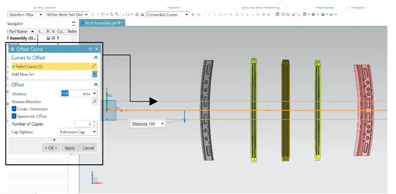
- After coming to the sketch, create 0-Y which will be the centre line of your roof, from that line 0-Y has to be offset 100mm- 100 mm respectively into up and down direction.
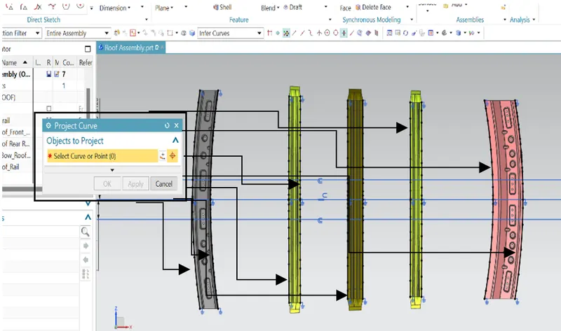
- The edges shown is to be projected (by project curve) in 2D Sketch.
- Intersection point has to be created as shown in the figure
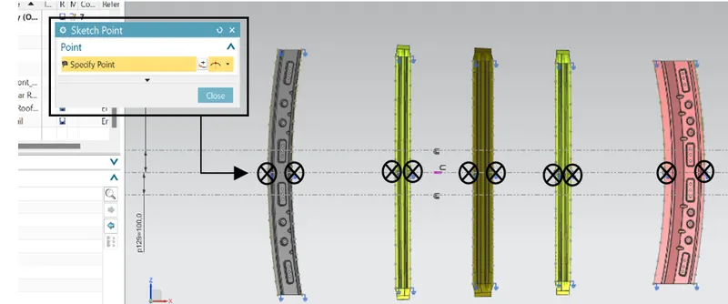
- Line has to be created with the help of the shown intersection point and with the help of the mid-point of that line, you have to create a vertical line.
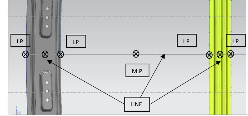
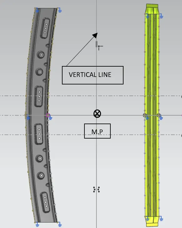
- That vertical line has to be offset 100mm-100mm relative right and left direction then create an intersection point at the points shown.
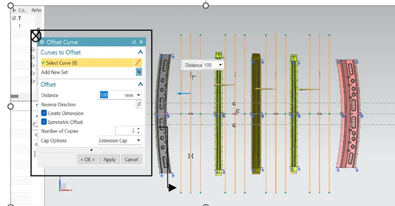
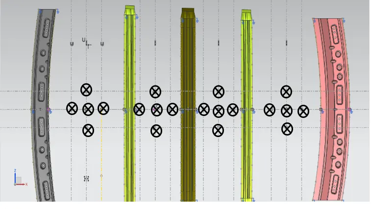
- Finish the sketch and project the points shown on the upper surface of the roof outer surface.
- Take the arc command and draw the arc with three-point option by specification start point, end point and mid-point. This operation you have to continue with all the horizontal and vertical points you petted. To display the radius of the created arc (Rx-Ry), the local radius command is used
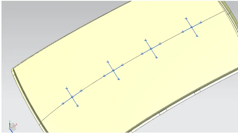
- You have to Measure all are Rx and Ry for your created curve
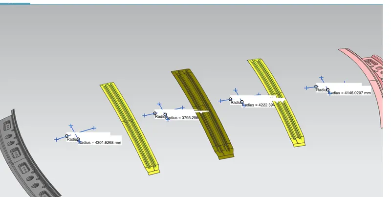
- You need to project the horizontal edges of your roof outer
- he help of the interception command would be to create the intersection point which is shown in the figure.
- With the help of rapid dimension, vertical measurement of the intersection point created above and below has to be taken.
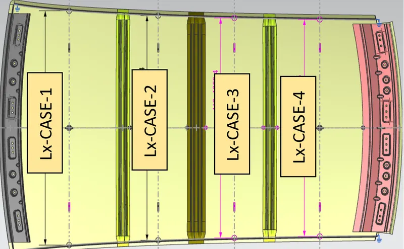
- You have to measure the distance between your front roof rail Centre to Rear roof rail centre
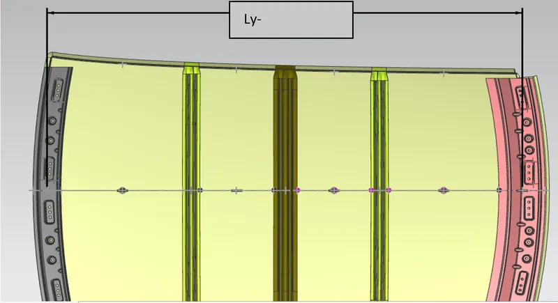
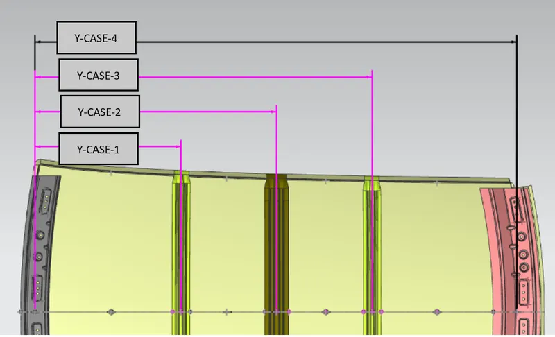
- To getting your Y value of each case you have to calculate the distance from centre of your front roof rail to the centre of the respective bow roof
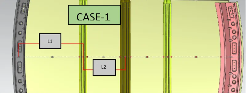
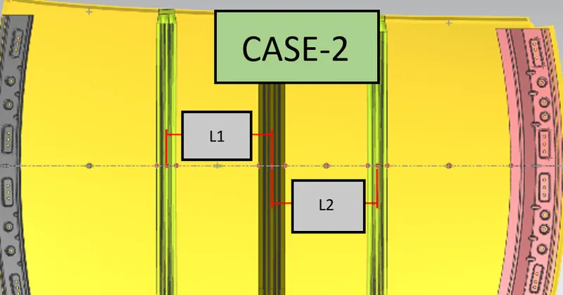
- L1 and L2 for each case
- Iy = Geometrical moment of inertia of Roof BOW (Y cross-section )[mm4]
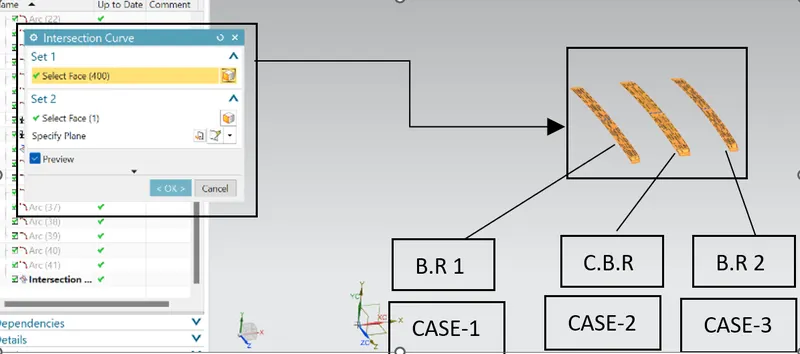
- In that case if you having reinforcement Centre Roof Rail
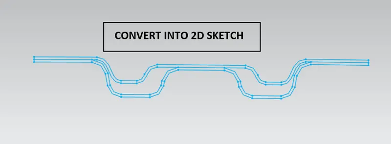
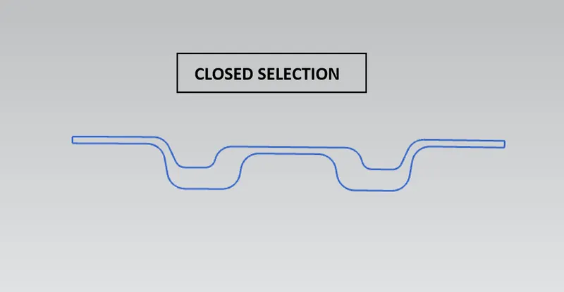
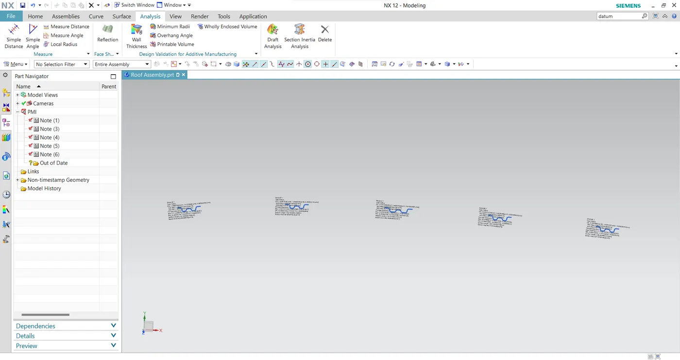
- Types should be solid in section inertia analysis
Qr = [Iy x t2] / [α x s x [(Rx + Ry)/2]2 x 10-8]
Note: The Qr value given over here is correct. There was a typo error in the formula given in the video.
Where
α = My x Lx2 x 10-12 , My = Y(Ly-Y)
Judgement condition = Qr ≥ 3.1
250 ≤ s ≤ 380
t = Roof plate thickness [mm]
Ly = Distance between the front and rear roof Rails on the Vehicle along with 0Y[mm]
Length of Roof panel with the center point between Roof rail Front /Rear as the front and rear reference point.
Lx = Distance between the Left and Right end of the roof on the Roof BOW [mm]
Width of the roof panel exposed on the surface.
Y = Distance front Front Roof Rail to Roof BOW[mm]
s = Distance for which Roof BOW bears divided load [mm]
s = L1/2 + L2/2
Iy = Geometrical moment of inertia of Roof BOW (Y cross-section )[mm4]
Rx = Lateral direction curvature radius of roof panel Y cross-section on Roof BOW [mm]
Roof panel curvature Radius of the Length Lx in Front view
Ry = Longitudinal Direction curvature radius of the Roof panel X cross-section on Roof BOW [mm]
Roof panel X curvature radius of length s in Side view
|
Snow Load Prediction Calaulation |
|||||||||||||
|
Rail Distance |
Iy |
Lx |
Ly |
t |
Y |
L |
Rx |
Ry |
My |
α |
s |
Qr |
Results |
|
Front Roof rail to Bow Roof-1 |
7447.08 |
1155.51 |
1950.87 |
0.75 |
305.00 |
305.00 |
200.00 |
203.62 |
501996.38 |
0.67 |
325.28 |
216.38 |
Pass |
|
Bow Roof-1 to Bow Roof-2 |
7873.45 |
1108.62 |
1950.87 |
0.75 |
650.56 |
345.55 |
200.00 |
200.56 |
845926.81 |
1.04 |
335.89 |
90.54 |
Pass |
|
Bow Roof-2 to Centre Bow Roof |
9591.60 |
1080.41 |
1950.87 |
0.75 |
976.79 |
326.23 |
200.00 |
200.01 |
951470.74 |
1.11 |
326.19 |
102.76 |
Pass |
|
Centre Bow Roof to Bow Roof-3 |
9276.18 |
1062.44 |
1950.87 |
0.75 |
1302.94 |
326.15 |
200.00 |
200.08 |
844213.53 |
0.95 |
336.14 |
127.09 |
Pass |
|
Bow Roof-3 to Bow Roof-4 |
7667.15 |
1049.83 |
1950.87 |
0.75 |
1649.07 |
346.13 |
200.00 |
200.31 |
497686.76 |
0.55 |
323.97 |
340.91 |
Pass |
Moment of inertia
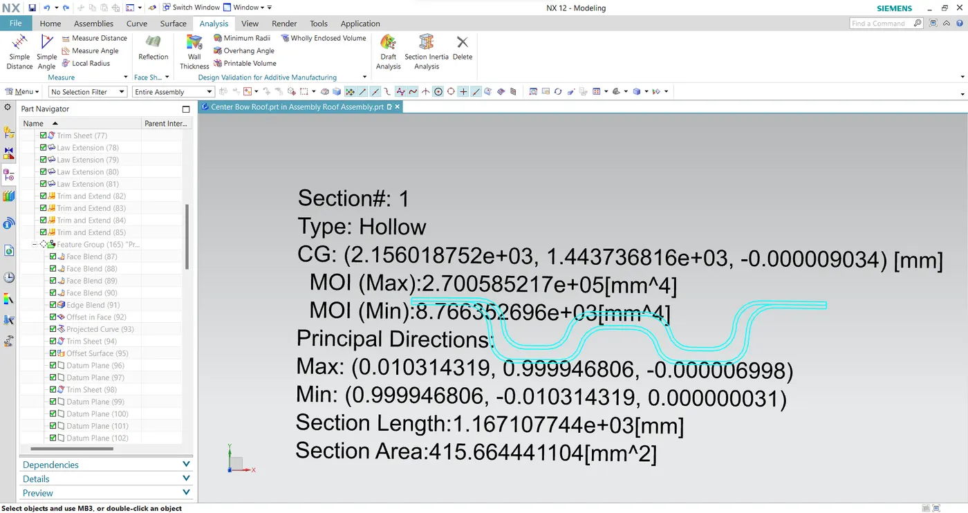
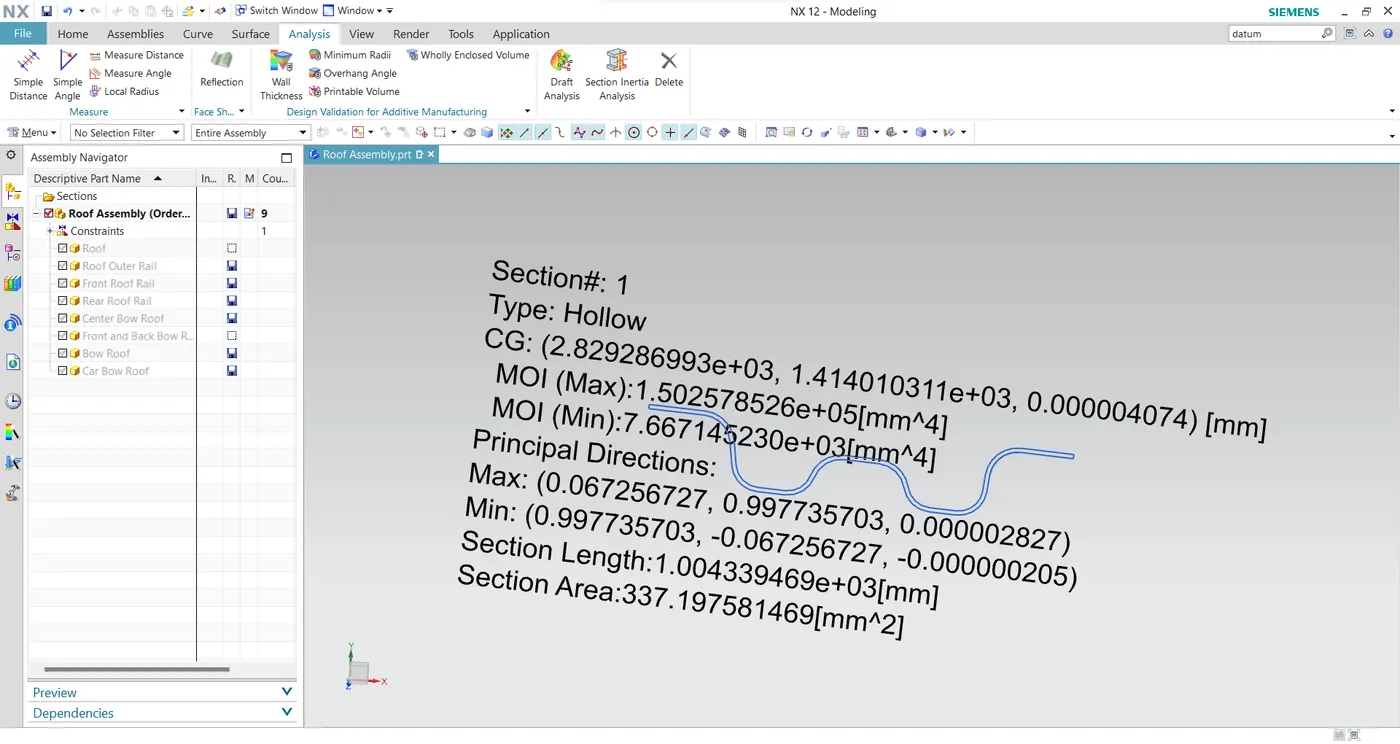
Moment of inertia is defined as the quantity expressed by the body resisting angular acceleration which is the sum of the product of the mass of every particle with its square of a distance from the axis of rotation. Section moment of inertia is used to predict the amount of deformation and deflection of a part. Higher the moment of inertia lesser the amount of deflection. Thickness, flanges and embosses will increase the section inertia. Here NX software used to find the moment of inertia using section inertia Analysis.
Here is the value for bow roof 1. Iy (min) = 7477.08 mm4
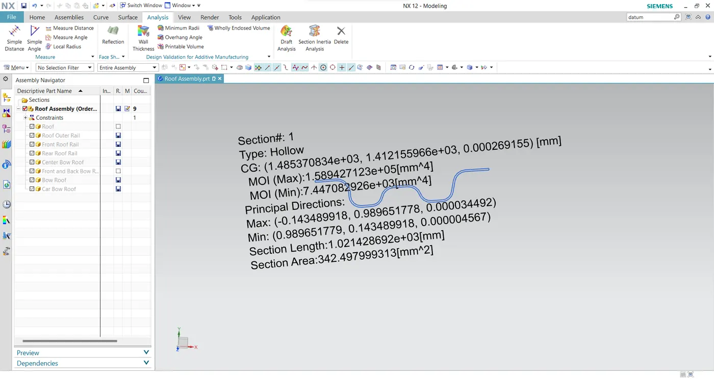
Here is the value for bow roof 2. Iy (min) = 7873.45 mm4
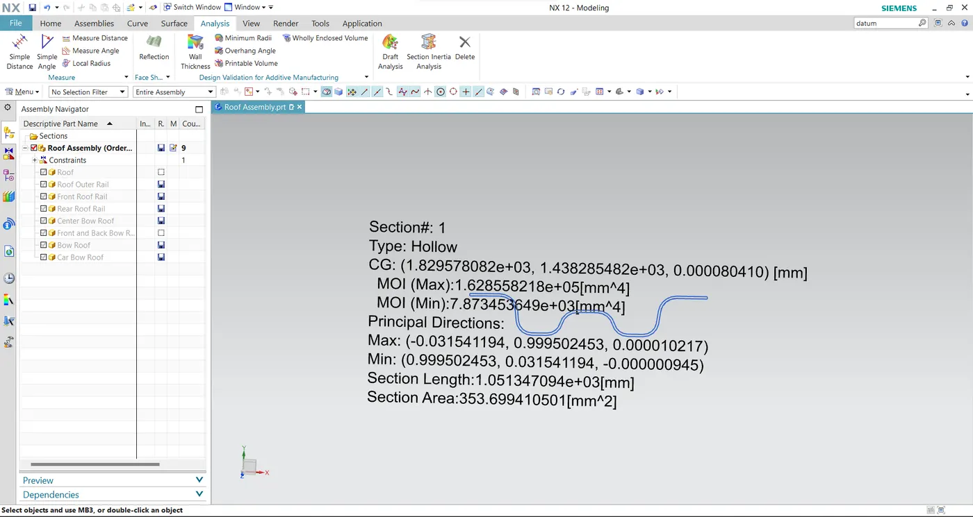
Here is the value for Centre Bow roof. Iy (min) = 9591.59 mm4
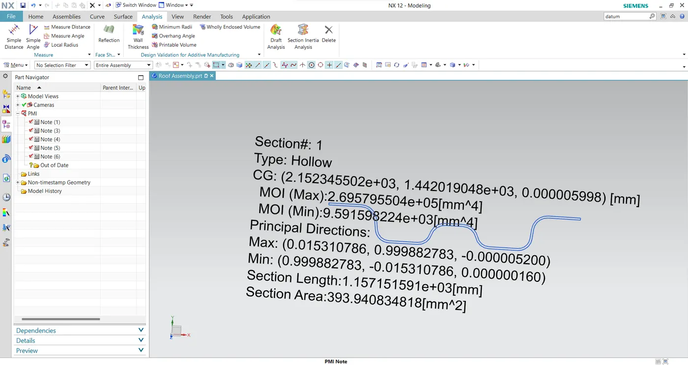
Here is the value for bow roof 3. Iy (min) = 9276.17 mm4
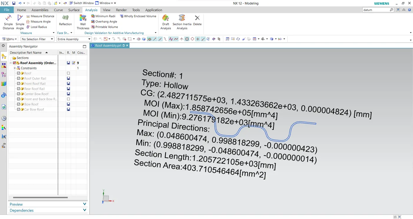
Here is the value for bow roof 4. Iy (min) = 7667.14 mm4
DRAFT ANALYSIS:
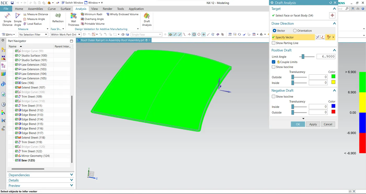
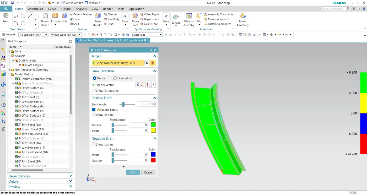
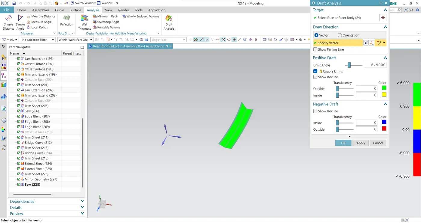
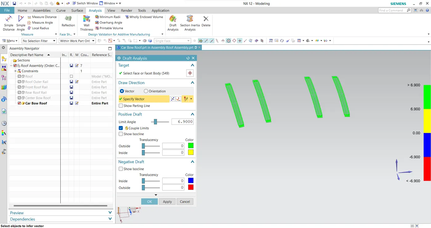
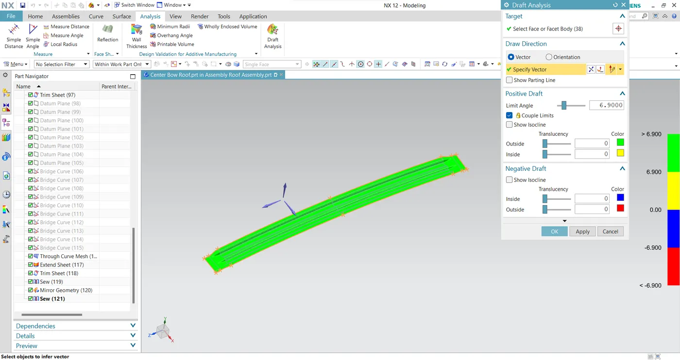
Draft analysis is done in NX software. We can change the draft angle and analyse is it clearing the required criteria. It is shown is different colour zones. So, identifying it will be easier. It will let us know that the part can be removed easily during manufacturing or not. Minimum draft angle of 7 Degree is considered for analysis. green colour infers on the parts that all face along the tooling direction has positive draft angle greater than 7 degree and passed in analysis.
Here are the parts that are made as per the master section and also clearing the draft analysis.
Outer Roof Rail Draft Analysis:
Front Roof Rail Draft Analysis:
Rear Roof Rail Draft Analysis:
Bow Roof Draft Analysis:
Centre Bow Roof Draft Analysis:
Car Roof Bottom View: