Roof Crush Test with Guidelines of FMVSS 216 Standard by using Radioss
Objective :
To simulate the Roof Crush Test with guidelines of FMVSS 216 and determine the given BIW frame is within compliance.
PROCEDURE:
Import
• Car
• Impactor
Transforms
• This will require (in order)
• A 180° rotation about the global z-axis with the point opposite to C as base point
• A 5° rotation about the axis through axis AB
• A 25° rotation about the axis through axis AC
• A translation to put point A at global ( -3500.00, 584.822, 1343.06)
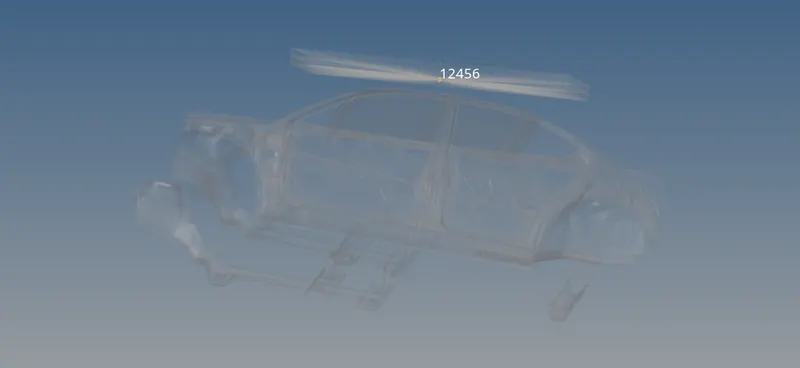
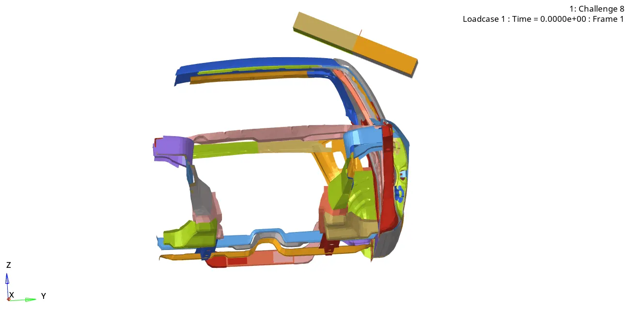
Reference image ( Full Vehicle Model )
Interfaces
• Create a Type 7 contact interface between the impactor and the car
• choose an appropriate stiffness definition
• choose an appropriate minimum gap
• change the coefficient of friction to 0.2
• choose the appropriate friction penalty formulation
• Save the data from the interface to the time history file.
Boundary condition
keep the suspension shock tower nodes locked in Z.
Impactor Boundary Conditions
• The impactor assembly contains a spring attached for stability. Create a BCS
collector to fix the free end of the spring.
• Create a moving SKEW to define the direction normal to the impactor’s
face.
• Create a BCS collector to guide the master node of the impactor rigid body
so that it is free to translate normal to the face of the impactor, but is fixed
in all other DOFs.
Imposed Displacement
• Impose the velocity of the impactor starting from 0 mm/s at t = 0. The
displacement of the impactor should be 200 mm @ 200 ms.
• Avoid abrupt changes in the acceleration of the impactor.
Control Cards
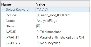
• /ANALY card
• /DEF_SHELL card,
• /DEF_SOLID card, and
• /IOFLAG card
• /SPMD card
• /TITLE card
Engine File
• Use a constant nodal time step
• Print time history every 0.0001 seconds
• Solve for 200 ms
• Create an animation file every 0.005 seconds
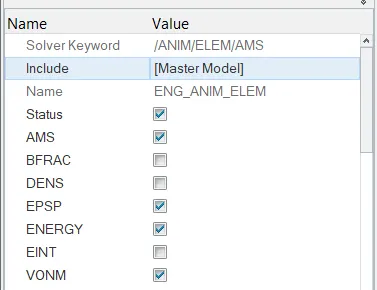
Include selected output in animation files:
• Elemental Energy
• Elemental equivalent plastic strain
• Elemental hourglass energy
• Elemental von Mises stress
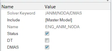
• Nodal added mass
• Turn on parallel arithmetic
Solution and Results Post Processing
• Run the model
• Plot force vs. displacement. Check that the FMVSS 216 target load of
47,000 N (= 3 * GVW) has been met.
• Plot the energy vs. time curves
Click here for the models
Note: Don't attach the google drive link of the completed model/simulation files in the challenge box. Attach the model/files in the challenge assets option provided.
Your Answers
Roof Crush - BIW
Import
• Car
• Impactor
Transforms
This will require (in order)
• A 180° rotation about the global z-axis with the point opposite to C as base point
• A 5° rotation about the axis through axis AB
• A 25° rotation about the axis through axis AC
• A translation to put point A at global ( -3500.00, 584.822, 1343.06)
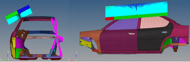
Import the geometry
- FMVSS_216_ROOF_IMPACTOR_coarse_0000
- neon_roof_0000
To setup the impactor upon the car roof,
- Tools > Rotate
- Choose the impactor, give angle as 180, choose A as Base point, and select axis as Z.
- Choose the impactor, give angle as 5, choose A as Base point, and select axis as Y.
- Choose the impactor, give angle as -25, choose A as Base point, and select axis as X.
- Tools > Transalate
- Select the impactor, give Value for X as 3500, Y as 584.822, Z as 1343.06
- Make some small value modifications for the impactor to be on a correct spot.
Interfaces
• Create a Type 7 contact interface between the impactor and the car.
• choose an appropriate stiffness definition.
• choose an appropriate minimum gap.
• change the coefficient of friction to 0.2
• choose the appropriate friction penalty formulation.
• Save the data from the interface to the time history file.
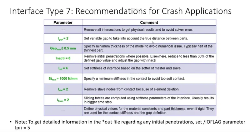
- Go to > Model > Groups > Create > Select the Type 7 Card.
- Input recommended properties for type 7.
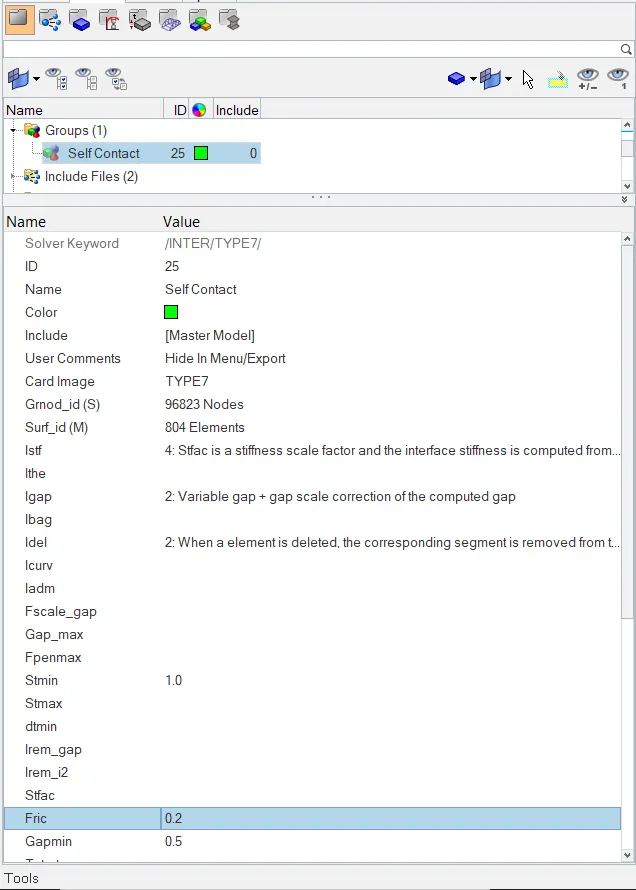
SELF CONTACT - Slave node (Car) | Master (Impactor)
- This contact is defined to impose the impactor(Master Node) to act upon slaves, in which deformation to be done.
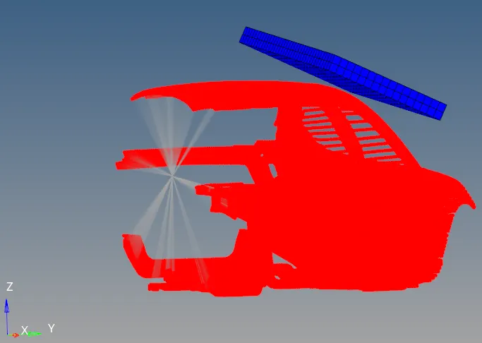
- Solver > TH > Create > Interface > Self contact
- Requests the output of interface data in Time Histrory
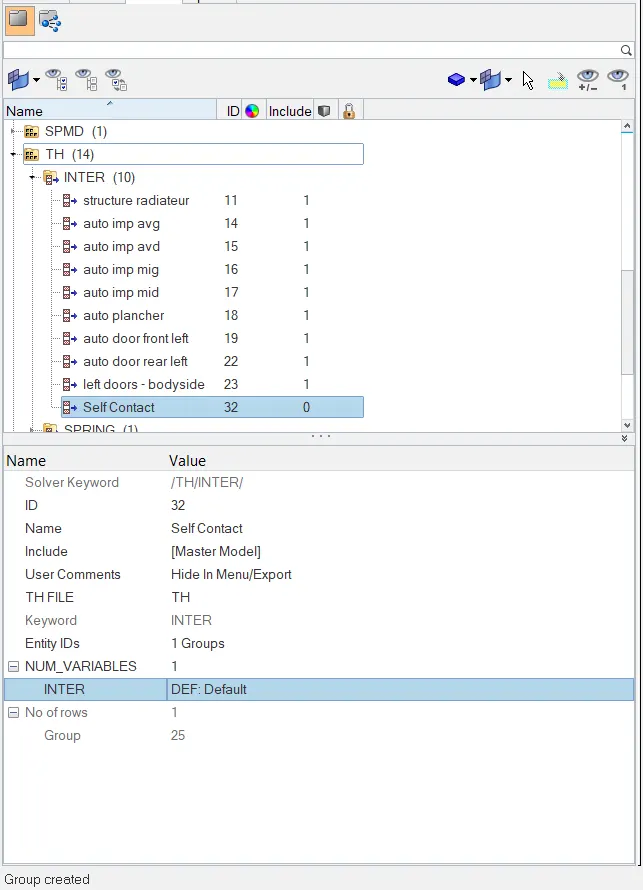
Creating Interface contact - Type 7
This interface is created, to prevent the self contact of own elements from the nodes (Slaves) and Elements (Master) Contact.
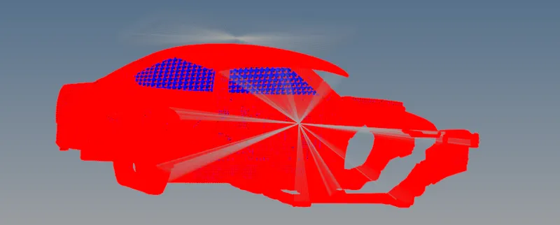
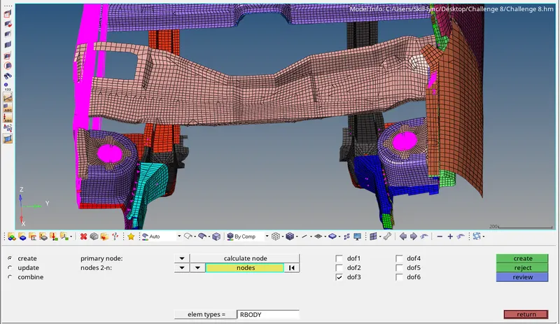
Boundary condition
keep the suspension shock tower nodes locked in Z.
Go to 1D > Rigids > Calculate Node > Edges > Lock Dof 3 (Z axis) > Select the edge in the circle to create boundary locked in z axis
Impactor Boundary Conditions
• The impactor assembly contains a spring attached for stability. Create a BCS collector to fix the free end of the spring.
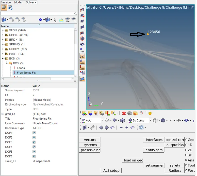
• Create a moving SKEW to define the direction normal to the impactor’s face.
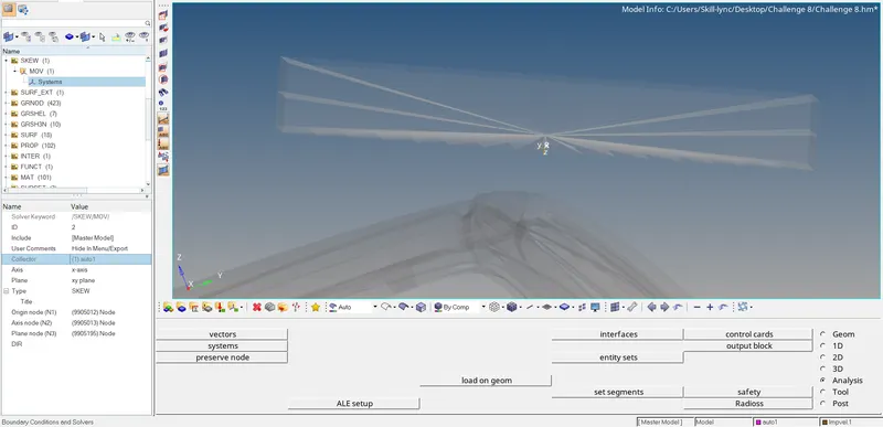
• Create a BCS collector to guide the master node of the impactor rigid body so that it is free to translate normal to the face of the impactor, but is fixed in all other DOFs.
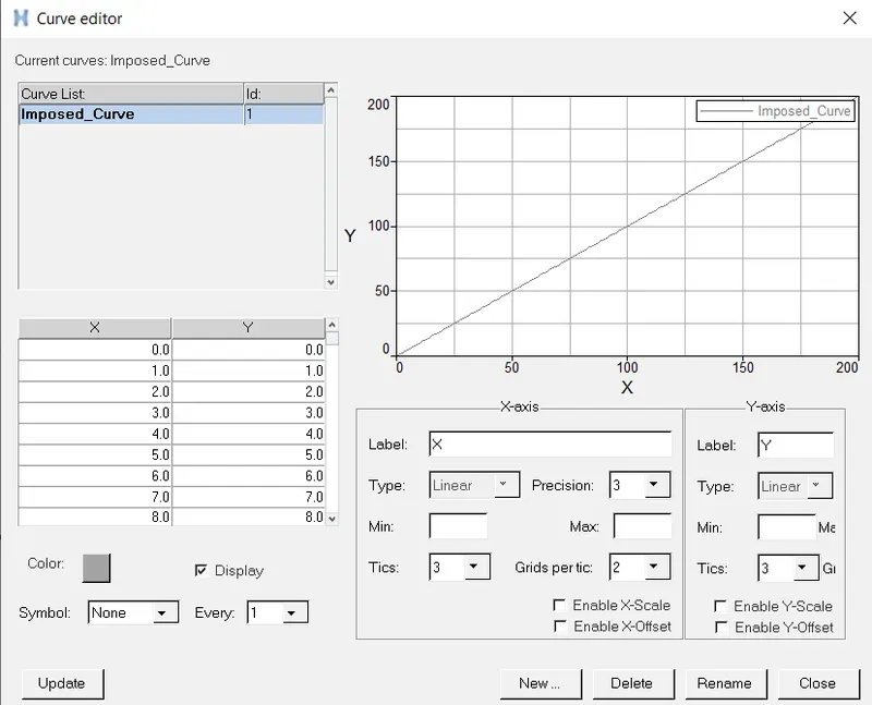
IMPOSED DISPLACEMENT :
- Create the curve for the displacement for the impactor to move.
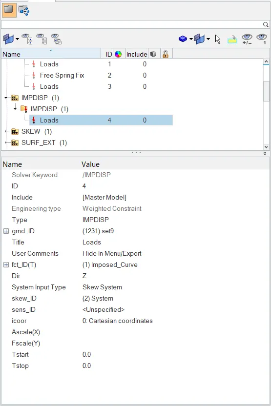
- Solver > IMPDISP
- Define the master node
- Functional identifier as the curve
- Direction along Z Axis
- Skew system to be defined in which it follows the impactor along th z axis (Normal)
CONTROL CARDS:
Check for the cards requested,
- /ANALY card
- /DEF_SHELL card
- /DEF_SOLID card
- /IOFLAG card
- /SPMD card
- /TITLE card
The above mentioned cards are verified in the cards section
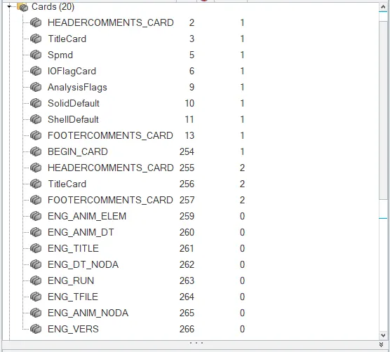
ENGINE FILE:
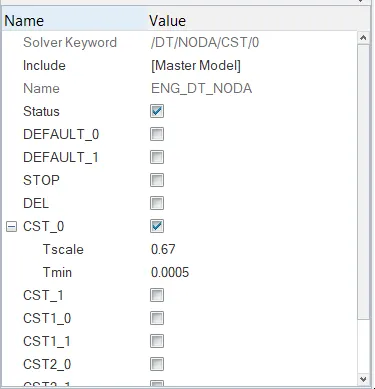
• Using a constant nodal time step
Tscale is the scaling factor for nodal time step 0.67, for Elemental it is 0.9
Tmin is the critical time step between node which is given as 0.0005ms
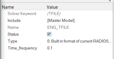
• Printing time history every 0.0001 seconds
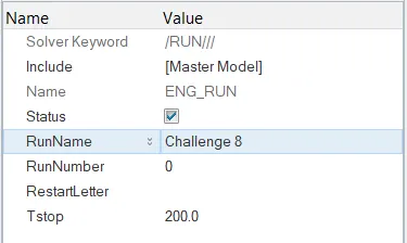
• Solving for 200 ms
• Creating an animation file every 0.005 seconds
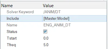
Include selected output in animation files:
• Elemental Energy (Energy)
• Elemental equivalent plastic strain (EPSP)
• Elemental hourglass energy (HOURG)
• Elemental von Mises stress(VONM)
• Nodal added mass(DMAS)
• Turn on parallel arithmetic
FREE CONNECTIVITY:
Free connectivity shows the parts that are free from the components which are not attached to any means.
These parts are to be connected in suitable manner using welds, rigids, etc.Here we use rigid for the connection.
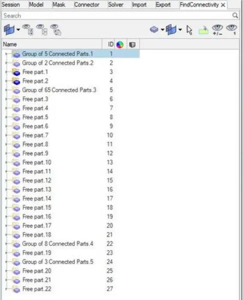
- 1D > Rigids
- Select Multiple nodes
- Calculate node
- Ensure the DOF locked in all the directions

- Use Rigids in the components near by for fixing the free parts
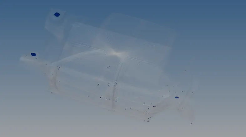
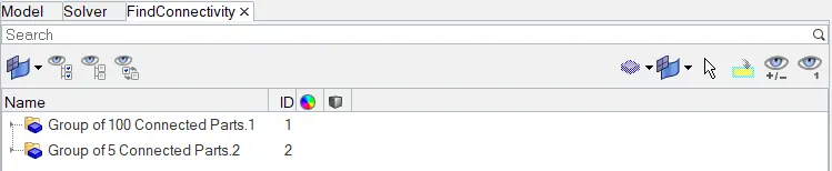
- Use find connectivity > check
- Ensure all the free parts are fixed to its mating parts.
- Here we have fixed the parts, remaining we see is that (Impactor and car)
PENETRATION CHECK:
Tools > Penetration check
Checks the penetrations in the interfaces created.
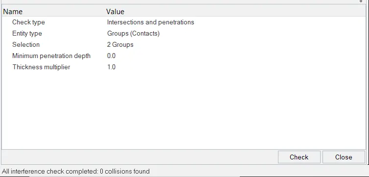
No penetrations found
MODEL CHECKER :
Tools > Model Checker > Check
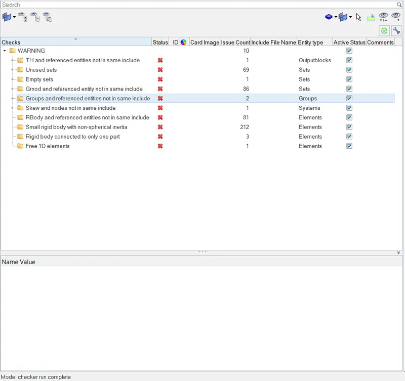
- After clearing Errors and understanding warning, move to analysis
- Analysis > Radioss > -nt 4 > Incluse connectors > Radioss >

OUTPUT FILE:
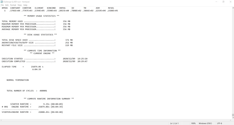
ERRORS OBSERVED :

HYPERVIEW SIMULATED OUTPUT:
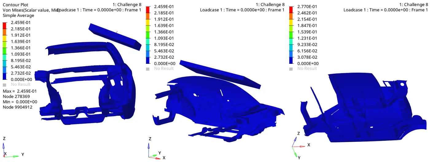
FORCE Vs DISPLACEMENT PLOT:
To create cross plot of Force Vs Displacement
- Select > Build plots > Load Case 1 > Displacement > Nodes > Select Centre node of Impactor

- Select Hypergraph 2D > Global Variables > Select Energies to be plotted > Magnitude > Apply.
- Go to file > Load > Preference File > Vehicle Safety Tool > Load > Math
- Math > 2Curves > Cross Plot.
- Select Curve x with holding shift key press displacement and holding on shift select the Curve Y as force and SELECT New Page and press Apply, to create cross plot data of Displacement Vs Force.
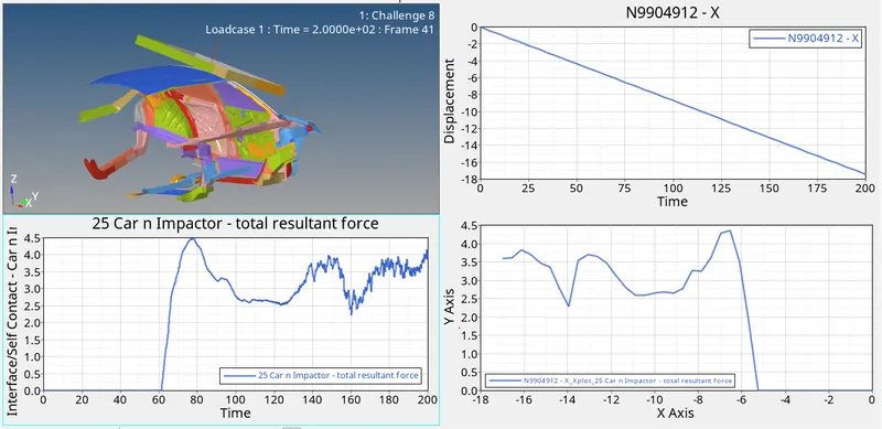
- The force acting during crush, is exhibited at 62mm. The force is max at 78mm with max of 4.5KN, and during the end of 200mm it is about 4KN.
ROOF CRUSH COMPARISON OF DATA
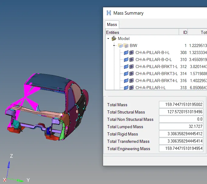
Mass of BIW (Approx) = 160
Neon_Full Body Weight = 1216.55 Kg
GVW= 3*1216.55*9.81 = 35803.06 N < 47000 N
It is acceptable
ENERGY PLOT :
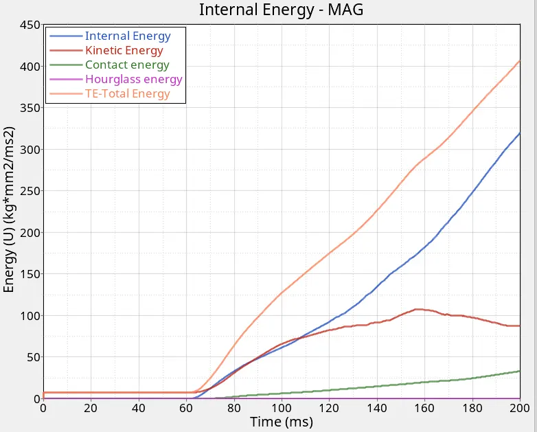
- Contact energy is observed max at the end of about 33.06Joule
- Kinetic energy is maximum of about 107.603Joule at 158mm.
- Total Energy is about 407.003 Joule starts at the time of impact and Increases as the crush happens.
- Internal Energy is max of 319.752 Joule and is the work done due to deformation.
- There is No Hourglass Energy found in the system.
CONCLUSION :
The model is analysed for the roof crush and is evaluated with the procedure requested and found to be under acceptable limit.