Roof Crash Simulation on Neon BIW vehicle model | HyperMesh
OBJECTIVE :
- To import the Car and the Roof impactor in Hypermesh to perform Roof Crash Simulation of the Car.
- To transform the Impactor over the roof of the car to obtain a proper location for roof crash simulation.
- To create all the necessary contact interfaces for the simulation.
- To apply the necessary boundary conditions on the car and the Impactor rigid bodies.
- To create all the required control cards and Engine file to ensure proper simulation.
- To study the crash behavior and the output results and discuss the results.
THEORY : The term Quasi Static is used to represent a sloe dynamic process as opposed to a fast dynamic process.
CASE SETUP AND EXECUTION :
The given Neon BIW vehicle model and the FMVSS 216 Roof Impactor model is as follows,
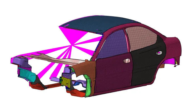
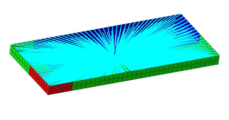
First, we will import the .rad starter file of the Neon BIW vehicle model which is named as neon_roof_0000.rad and Roof Impactor model which is named as FMVSS_216_ROOF_IMPACTOR_coarse_0000 in Radioss using Import Solver Deck option. Then we will check the unit system which is followed in the model under BEGIN_CARD. So for this model, we will see that the unit system followed is [kg mm ms]. Now we will create all the required things for a roof crash.
Positioning the Roof Impactor –
When the car and the impactor is imported in Hypermesh, we will see that the roof impactor is located below the car as follows,

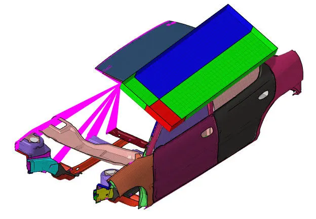
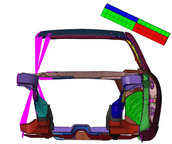
So we have to transform the roof impactor above the car with its center aligning with the left B-pillar of the car for a roof crash. So we will perform some transformations by using commands such as Rotate and Translate from Tool page. After completing all the transforming operations, we will get the final position of the impactor as follows,
Interface –
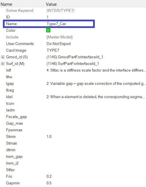
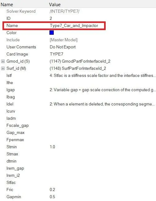
For this model, we will create two Type 7 interfaces. One for all the components of the car as it is self-impacting or the nodes and elements of the model will have a contact between them and other Type 7 interface between the Car and the Roof Impactor. So, we will navigate to Solver browser and we will delete all the existing interfaces. Then we will right click and navigate to Create > INTER > TYPE 7. Under Type 7 interface card, we will select all the components of Neon BIW vehicle for slave nodes and master surface in Grnod_id(S) and Surf_id(M) respectively. Then we will define all the recommended parameters for Type 7 interface i.e. Istf = 4, Igap = 2, Idel = 2, Inacti = 6, Stmin = 1 kN, Fric = 0.2, Gapmin = 0.5, Iform = 2. In the same way, we will define Type 7 interface between the Car and the Roof impactor but for this case, under Type 7 interface card, we will select all the components of Neon BIW vehicle for slave nodes and all the components of FMVSS 216 Impactor for master surface in Grnod_id(S) and Surf_id(M) respectively.
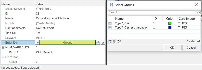
To save the data from the interface between Car and Roof Impactor to time history file, we will navigate to Output Blocks in Model browser. We will create a new Output block and under Entity ID option, we will select the Type7_Car_and_Impactor. After the simulation, the data will be saved to time history file.
Boundary Conditions –
For the roof crash scenario, we will have to create some boundary conditions on the model so as to restrict or allow required motions. So here, we will create three boundary conditions for Suspension, Impactor Spring and Impactor rigid body.
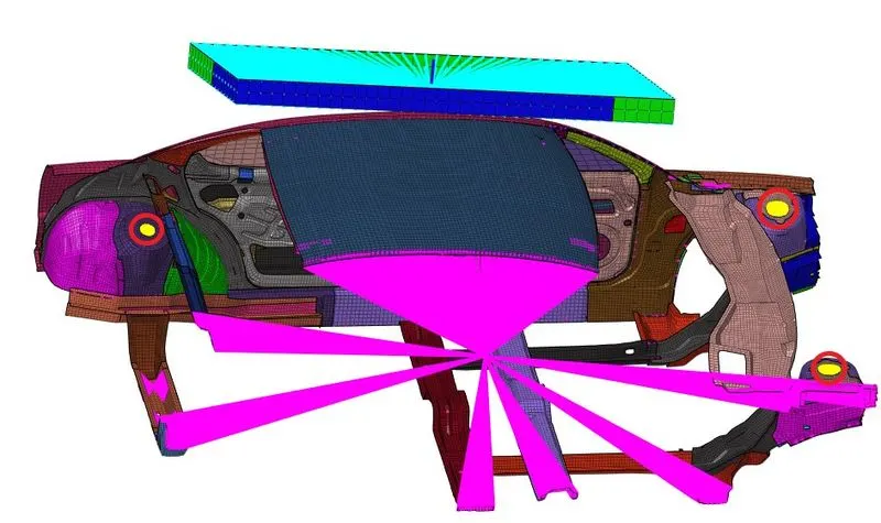
- Suspension – As there are no wheels and suspension system in the model, we will create rigid bodies at the suspension part. So we will navigate to 1D > Rigids and change the option of primary node to calculate node. Then we will select nodes where we want to create rigid body element. As we have to keep the suspension shock tower nodes locked in Z-axis, we will tick dof 3 which will lock the translation motion of the rigid body master node.

In this way, we will create the rigid bodies on all the suspension parts of the vehicle as shown below,
Note: Sometimes, the software automatically changes the boundary conditions that are applied to the rigid bodies during simulation. In this case, the DOFs on rigid bodies changed to dof 123 after the simulation. Creating different BCS collector can solve this issue but it also increases the energy error in the simulation.
So we will create a BCS to keep the suspension shock tower nodes locked in Z-axis. So under Solver browser, we will right click and navigate to Create > BOUNDARY CONDITIONS > BCS. We will rename it as Suspension and select the three master nodes of the suspension rigid bodies as shown below.
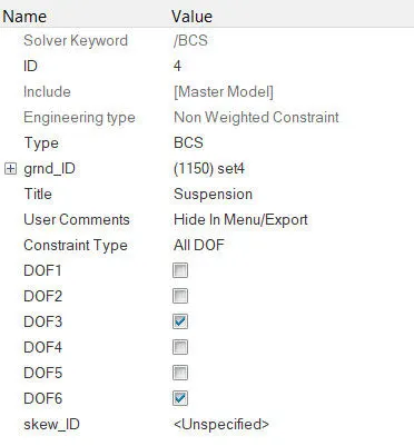
- Spring – The impactor assembly contains a spring attached for stability. We have to create a BCS collector to fix the free end of the spring so when the impactor is in motion during simulation, the effect of the spring on Impactor can be obtained. So under Solver browser, we will right click and navigate to Create > BOUNDARY CONDITIONS > BCS. We will rename it as Spring and select the free end of the spring for grnd_ID and tick all DOFs to fix the free end as shown below.
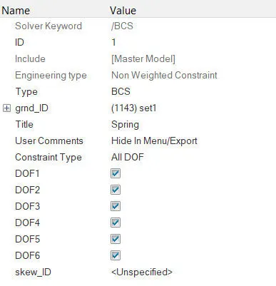
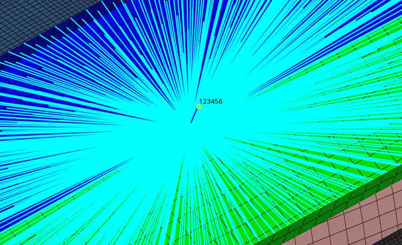
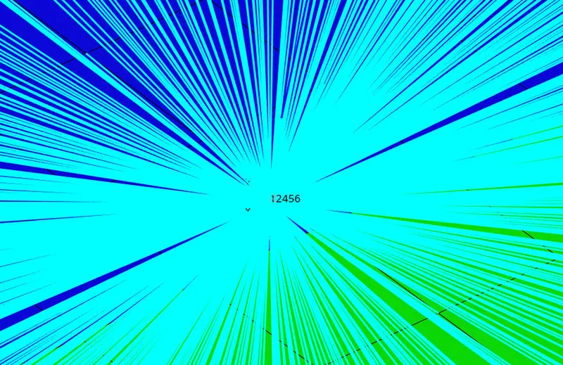
- Impactor – For the Impactor, we want it to have translational motion which is normal to the face of the Impactor. So to have an axis which is normal to the face of the Impactor, we will create a moving Skew at the master node of the Impactor Rigid Body. Under Solver browser, we will right click and navigate to Create > Skew > MOV and we will create it by using axis direction where we will select the origin node on Impactor Rigid body and choose the direction of the axes which will give us the axis normal to the Impactor as shown below.
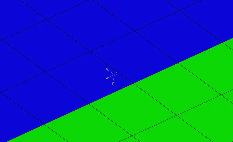
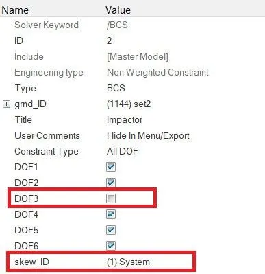
Now, in the same way we will create a BCS collector for the Impactor Rigid Body as we did earlier. For grnd_ID, we will select the master node of the Impactor Rigid Body. We have to provide the translation of the Impactor which normal to the face of the impactor, so we will tick all the DOFs except DOF3 due to which it is free to translate in normal direction of Z-axis. Here, one important thing is to mention moving skew system in skew_ID to get the motion according to the moving skew.
Imposed Displacement –
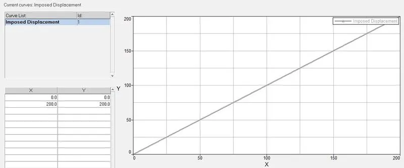
For the simulation of roof crash, we have to impose some velocity to the Impactor to displace it towards the roof of the Neon BIW car. We have to impose the velocity of the impactor starting from 0 mm/s at t = 0 and the displacement of the impactor should be 200 mm at 200 ms. To obtain the required displacement, we will create a curve function. So, under Model browser, we will right click and go to Create > Curve where we will create new curve with name Imposed Displacement and mention the curve coordinate as follows,
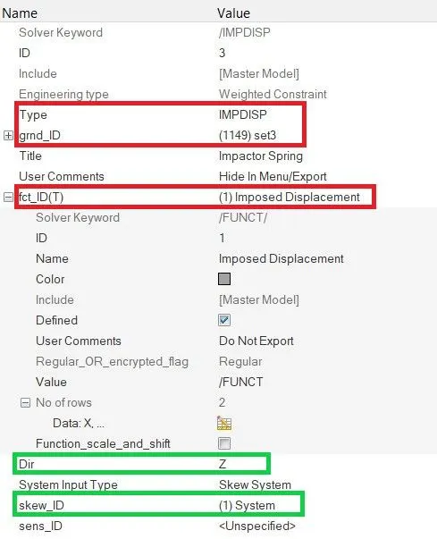
Now we will create the Imposed Displacement card in Solver Browser by right clicking and navigating to Create > BOUNDARY CONDITIONS > IMPDISP. Under IMPDISP card, we will select the master node of Impactor Rigid body in grnd_ID and we will apply the curve function which we created under fct_ID. The important thing in this case is we have to mention the direction of the imposed displacement of the Impactor. As we want it to translate in normal direction and towards the Car roof, we will mention the created moving skew as our direction reference and impose the direction in Z-axis of the skew as shown below.
Control Cards and Engine File –
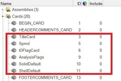
For Radioss solver, some control cards are necessary for its operation. Some of the important cards are Title Card, Spmd, IOFlag Card, Analysis Flags, Solid Default, Shell Default, etc. In our model, under Cards tree in Model browser, we can observe that the control cards which we mentioned are already defined as shown below,
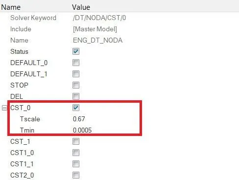
Now we will prepare all the required engine files necessary for simulation. We want constant nodal time step. So we will create an Engine file for ENG_DT_NODA where we will mention minimum nodal time step in Tmin as 0.0005 and Tscale as 0.67.
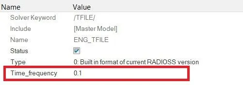
We have to print time history for every 0.0001 s in Radioss solver. So we will create a new engine file for ENG_TFILE where we will mention Time_Frequency as 0.1 ms.
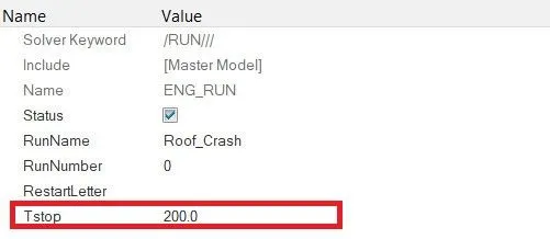
We have to mention our solver run time as 200 ms so we will mention it under ENG_RUN card in Tstop parameter as shown below.
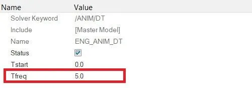
For Radioss Simulation, we want our animation file to be created for every 0.005 s. So we will create ENG_ANIM_DT card and mention Tfreq as 5.0 ms as shown below.
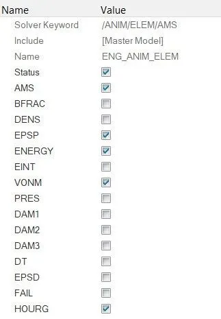
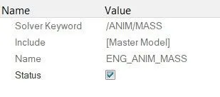
We also need some output in animation files which include Elemental Energy (ENERGY), Elemental equivalent plastic strain (EPSP), Elemental hourglass energy (HOURG), Elemental von Mises stress (VONM) and Nodal added mass. So we will create ENG_ANIM_ELEM card and for Nodal added mass, we will create ENG_ANIM_MASS card and tick the mentioned output boxes as follows.
Along with these Engine card, we will create some more cards required for simulation namely ENG_ANIM_NODA for nodal animation, ENG_RFILE for restart file frequency cycles, ENG_TITLE for title of the model, etc. The parallel arithmetic option is already On in the /ANALY card.
Penetration Check –
To check for penetrations in the model, we will go to Tools menu on Menu bar and click on Penetration Check option. In Penetration check panel, we will select all the components and click on Check command. The software will check for penetrations and then display the results as shown below,
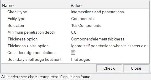
So there are no penetrations or intersections in the model.
Model Checker –
To check the quality of the model in Hypermesh, in Menu Bar we will navigate to Tools > Model Checker > RadiossBlock. This will open a new Model Checker browser.
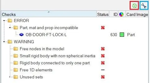
In this browser, we will click on Run checks command which is at the top right side in the above figure, indicated in red box. After running the checks, we will click on Auto correct command which is in blue box, through which the software will automatically perform the possible corrections and give a green tick in status bar. From above figure, we can ensure that the quality of the model is good for simulation and the given errors and warnings can be ignored.
Now we can proceed to run the simulation. So we will navigate to Radioss in Analysis page. Here we will save the model to a specified path and in options, we will type –nt 4 and then click on Radioss option to run the analysis.
SIMULATION AND RESULTS :
First, we will check Energy error and Mass error. So we will open the engine .out file of the model and check the last row for Energy and Mass error as shown below.
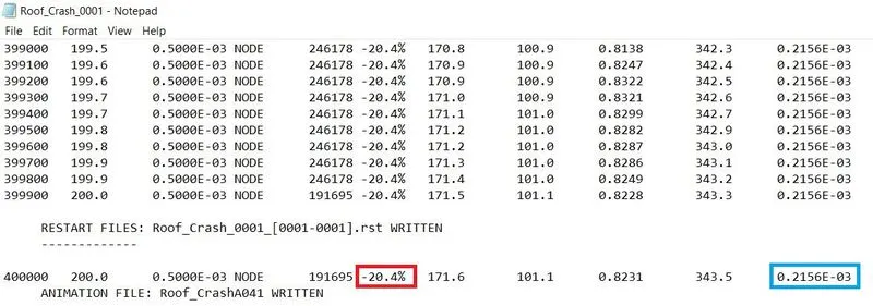
The red box indicates Energy error which is -20.4% and blue box indicates Mass error which is very negligible. The acceptance range for energy error is -15.0% and the results above shows that the energy error exceeds the acceptance range. This is mainly due to the boundary conditions which we applied on rigid bodies. As the rigid bodies are already defined with boundary conditions, those boundary conditions sometimes change after the simulation to DOFs 123. To prevent this, we applied external boundary conditions on the rigid bodies using BCS collector. Thus some amount of energy error is induced due to over defining boundary conditions. As the model is not a complete vehicle model, some parts of the car ruptures on increasing force from the impactor which also results in energy error. Due to all these factors, the energy error in the model exceeds the acceptance range.
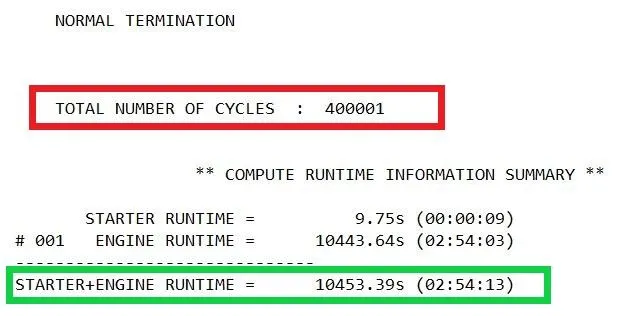
The total number of cycles used is 400001 and the total runtime of the simulation is 10453.39 s.
To view the simulation results, we will switch to HyperGraph. In HyperGraph, we will load .h3d file from specified path and we will play the simulation.
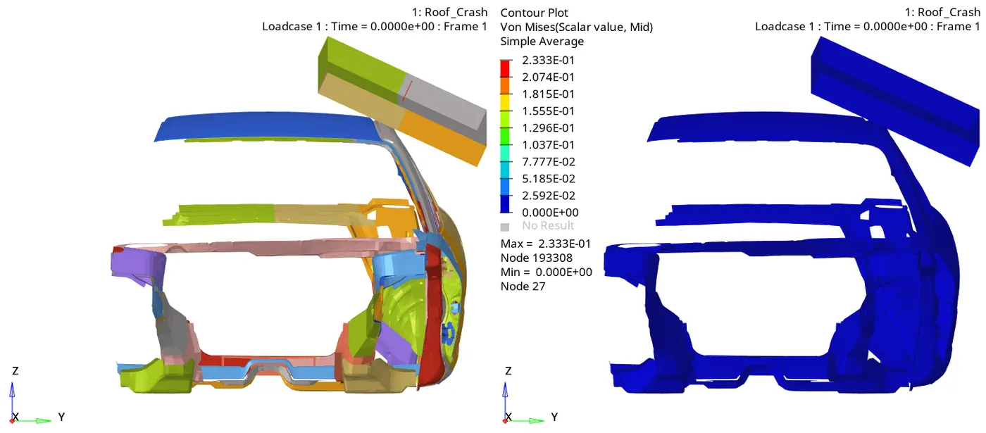
In the above crash simulation of the vehicle, we can see the Impactor is impacting on the Car Roof and its center is in line with the B-pillar.
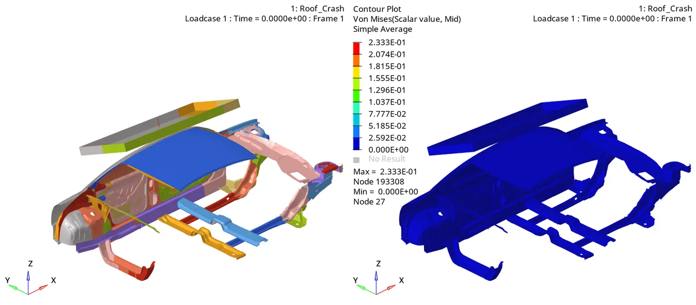
After the impact, the roof starts deforming and the developed forces and displacement are then transferred to other parts of the car. Due to high amount of force experienced on the vehicle body, some parts of the vehicle fail and break after some time. As the connectivity between all the components is not defined properly, we can see some parts getting detached from the vehicle body like the door assembly. From the Von Mises stress plot, we can say that the stress distribution is quite good in the vehicle after the crash whereas the Impactor being rigid in nature, there is no stress developed on it. There are very few areas where we can see stress concentration. Generally the stress is more at the point of impact between the roof and the impactor and then it is transferred to the opposite side of the roof and also at one of the cross member adjacent to B-pillar. As the model is an incomplete and reduced model, the deformations seen in the simulation are unrealistic deformations.
Energy Plot –
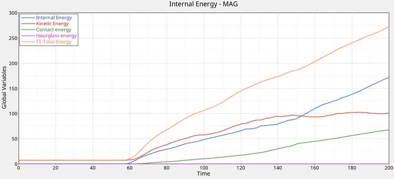
From the above simulation, we can see that there was some kinetic energy in the system. As it is a quasi-static simulation, the mass is added to the nodes in the model and thus the kinetic energy keeps on increasing till the end of the crash. The contact energy increases after 56 ms that is when the impactor comes in contact with the roof of the car. The internal energy also increases at the time of contact as the heat generated in the system keeps on increasing. There is negligible amount of hourglass energy in the system. All these energies along with energy error contribute to Total energy of the system which is around 275 J at the end of the crash.
Force vs Displacement Plot –
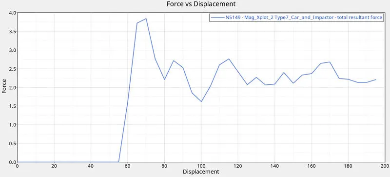
The Force vs Displacement plot is plotted by using MATH option in Hypergraph 2D. Through the MATH option we cross plotted the Force and Displacement curve. From the above plot, we can see that the force is applied from the impactor to the car at 56 ms and increases up to 3.8 kN. Then its nature is depending on the resistance offered by the car. The displacement and never reaches 200 mm due to the resistance and some rebound action in the system.
Mass –
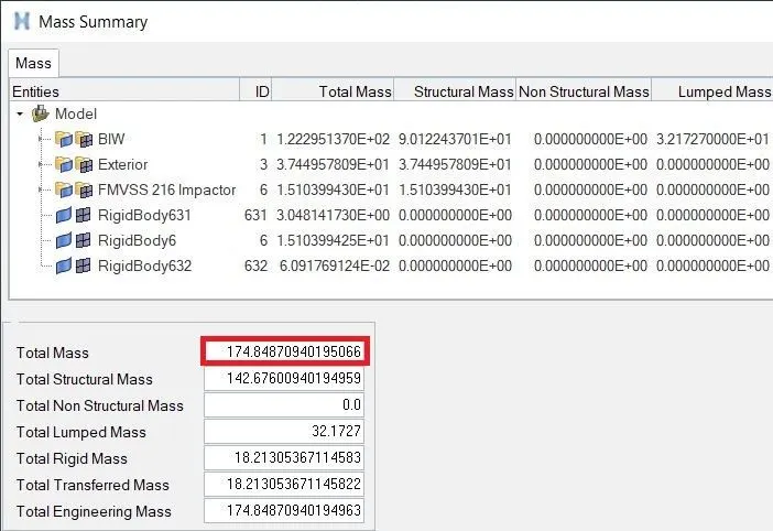
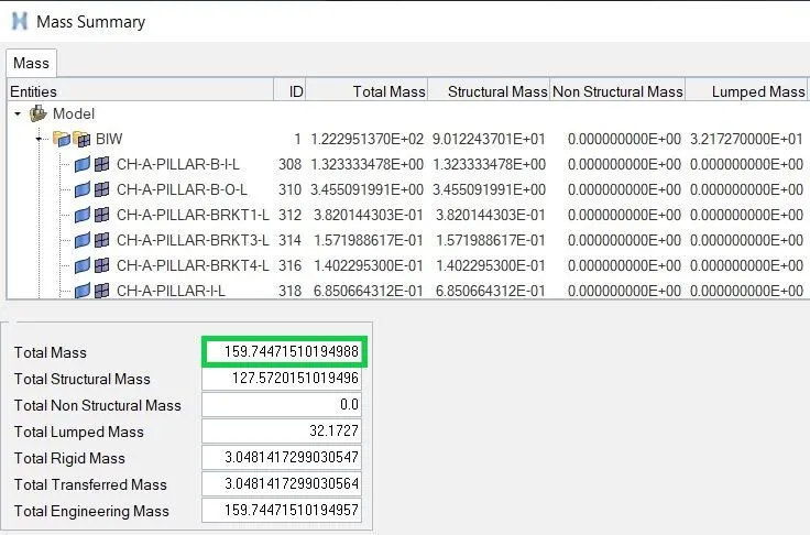
The total mass of the system including car and roof impactor is 174.84 kg whereas the total mass of the vehicle is 159.74 kg. To convert it to weight, we will also consider the gravitational force. Thus the Gross Vehicle Weight (GVW) value is,
`159.74 ×9.81=1567.0494 N`
The target load is considered as three times the GVW.
`Load=3×GVW=3×1567.0494=4701.1482 N`
According to FMVSS 216, the target load should be 47000 N but the load attained is 4701.1482 N which is almost 10% of the target load. Due to software restrictions, the model is a reduced model and not a real model. So if the complete car model is simulated, the target load can be reached.
CONCLUSION :
The FMVSS 216 Roof Impactor is impacted against the Neon BIW vehicle model to study the roof crash scenario of the vehicle. As the model is reduced to limited parts, we get somewhat unrealistic deformations and results but based on the results and graphs, we are able to study quasi-static case which is different from frontal crash and side crash.