Roof crash analysis using Hypermesh
Aim:
To run a roof crash analysis with the BIW component add and run the crash with given parameters.
Objective:
Roof crash-BIW
- Import and Transform the impactor from bottom to roof of the car as per the given angle.
- Create a Type 7 interface for the car and the impactor.
- Create Rigids in shock tower nodes and lock the nodes to axis z.
Impactor Boundary Conditions
• The impactor assembly contains a spring attached for stability. Create a BCS
collector to fix the free end of the spring.
• Create a moving SKEW to define the direction normal to the impactor’s
face.
• Create a BCS collector to guide the master node of the impactor rigid body
so that it is free to translate normally to the face of the impactor, but is fixed
in all other DOFs.
Imposed Displacement
• Impose the velocity of the impactor starting from 0 mm/s at t = 0. The
displacement of the impactor should be 200 mm @ 200 ms.
• Avoid abrupt changes in the acceleration of the impactor.
Engine File
• Use a constant nodal time step
• Print time history every 0.0001 seconds
• Solve for 200 ms
• Create an animation file every 0.005 seconds
Introduction:
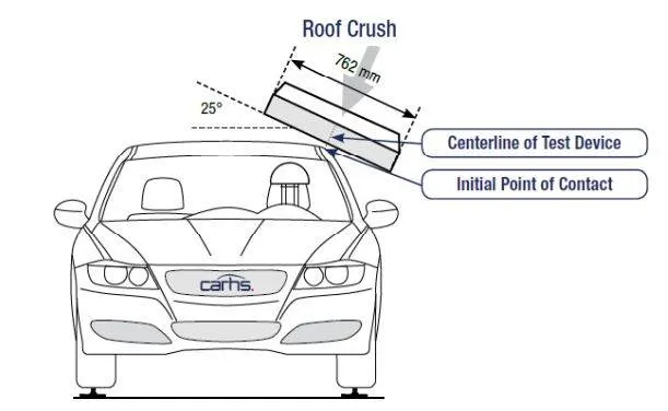
Quasi-static method:
A quasi-static test is described as the energy absorption capability of the composite when they are crushed under axial loads. The quasi-static tests are performed using a hydraulic press where the specimen is crushed at a very low crosshead speed between two parallel steel plates
Crash Testing Requirements:
Regulatory testing: FmVss,ECE,AU,JS,BNVSAP
Consumers testing: NCAP
- The regulatory test provides an answer to the question, whether the car passes or fails If injury recorded in dummy is less than the standard value then it is said to be passed.
- Consumer testing will give a star rating based on the injury results. They will also give a rating based on individual component performance from the car.
- The results from the above testing drive the overall business decisions as well.
Procedure:
- In this case, We have to import both impactor and car the given model and then set the given parameters.
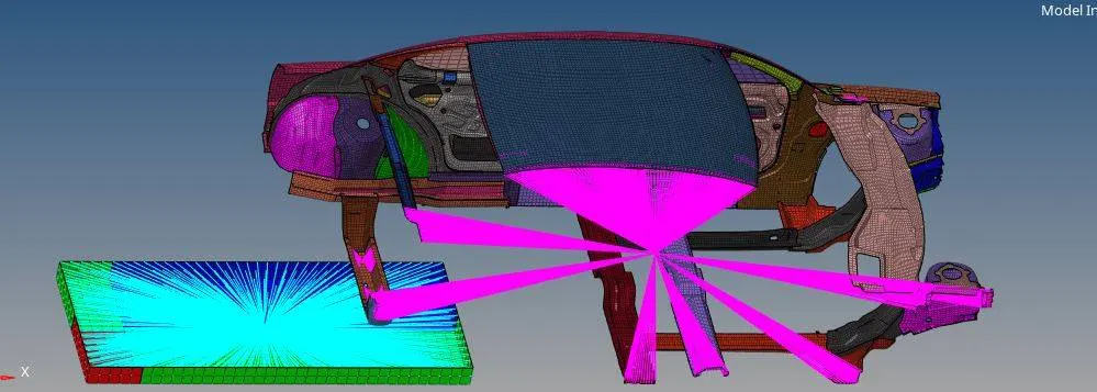
2. Now to bring the impactor above follow the given parameters
This will require (in order)
• A 180° rotation about the global z-axis with the point opposite to C as the base point
• A 5° rotation about the axis through axis AB
• A 25° rotation about the axis through axis AC
• A translation to put point A at global ( -3500.00, 584.822, 1343.06)
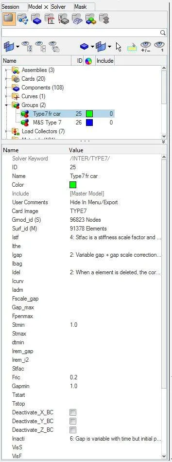
3. To Create the contact interface Type 7 with friction 0.2 and recommended parameters.
Igap=2 (set the variable gap to take into account the true distance between parts.)
Gapmin = 0.5 mm (Specify minimum thickness of the model to avoid numerical issues.)
Inacti = 6 (Remove initial penetration where possible. Elsewhere, reduce to less than 30% of the defined gap value and adjust the gap with Inacti)
Istf= 4 (Set stiffness of interface based on the softer of master and slave)
Stmin = 1000N/mm (specify a minimum stiffness in the contact to avoid too soft contact)
Idel =2 (Removes the slave node from contact because of element deletion)
Iform = 2 (Sliding forces are computed using stiffness parameters of the interface. Usually results in bigger time step)
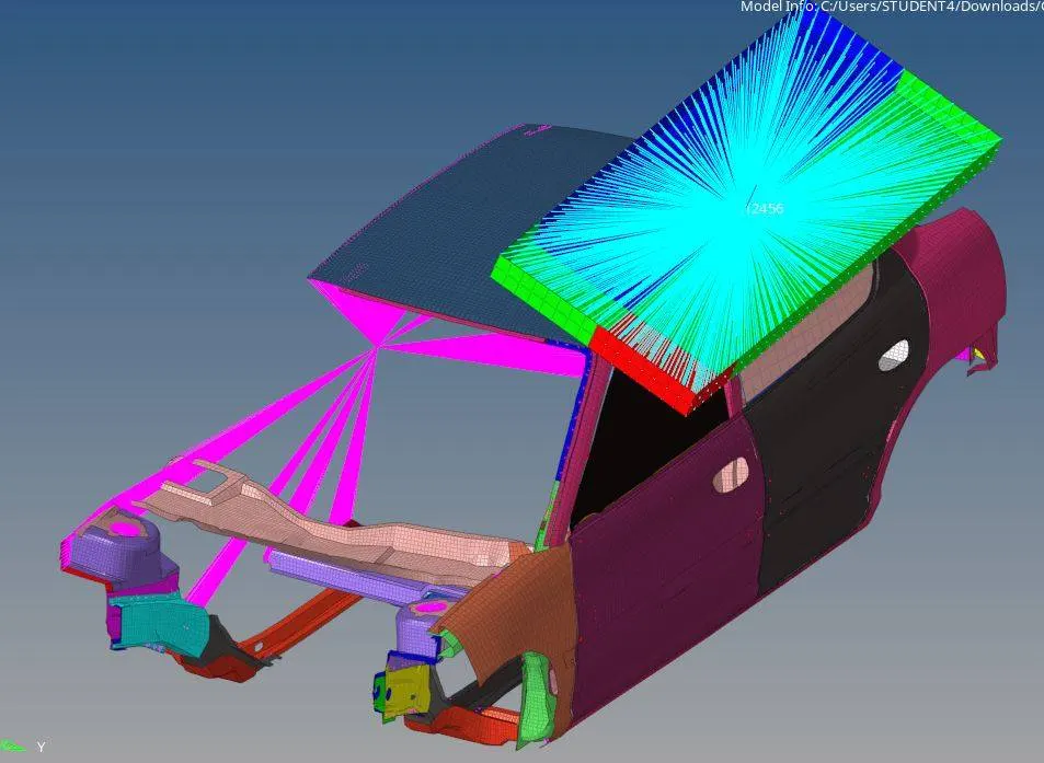
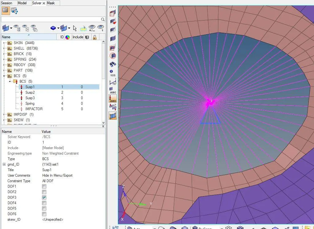
4. In this model we have to create the suspension rigids and create BCS for all three master node lock Z direction.
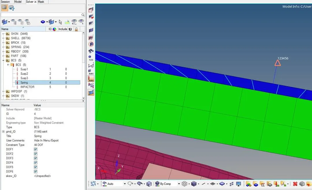
5. Now create BCS on the free end of impactor spring.
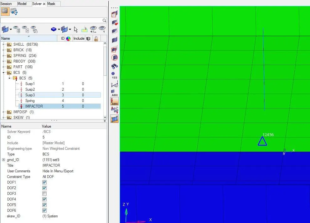
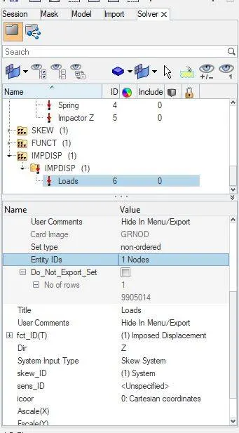
6. A moving skew is defined at a direction normal to the impactor’s face and BCS collector is the master node of the impactor rigid body so that it is free to translate normally to the face of the impactor, but is fixed in all other DOFs.
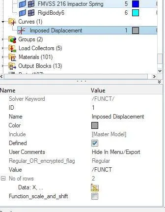
7. Impose the velocity of the impactor starting from 0 mm/s at t = 0. The displacement of the impactor should be 200 mm @ 200 ms.
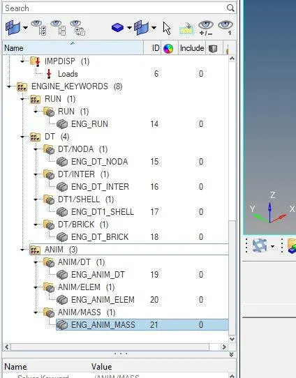
8. Now in engine card give the following values for the simulation, constant nodal time step, print time history every 0.0001 seconds, solve for 200 ms and Create an animation file every 0.005 seconds.
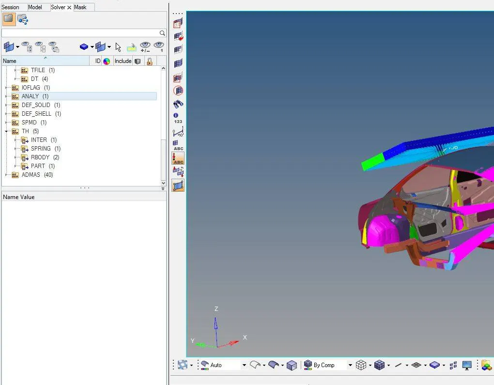
9. To get the output results in the graph we have to create TH for all the new cards.
Result:
Elemental Energy:
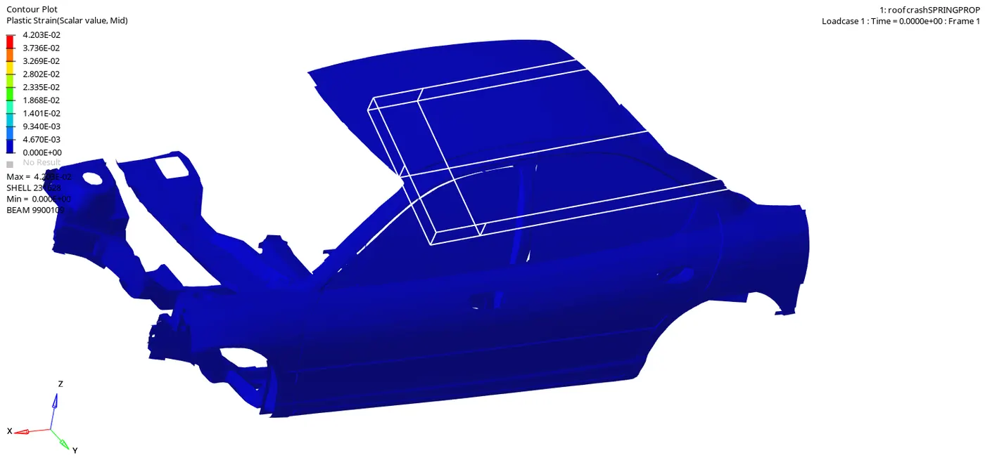
Elemental equivalent plastic strain:
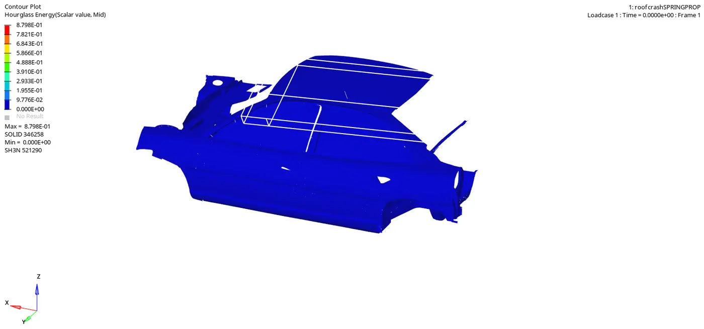
Elemental hourglass energy:
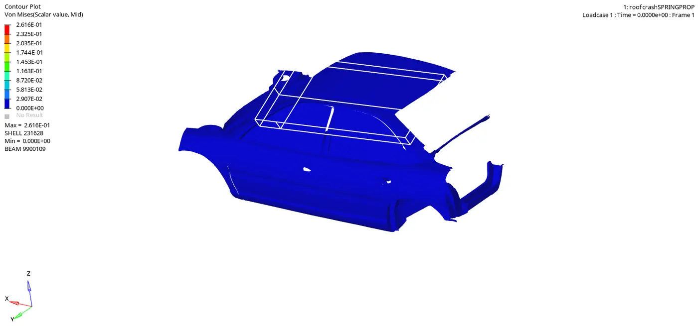
Elemental von Mises stress:
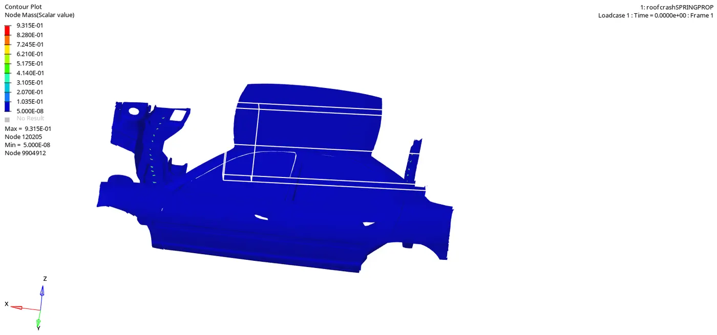
Nodal added mass:
Turn on parallel arithmetic:
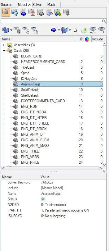
If the parallel arithmetic flag is set ON, the same numerical results will be obtained irrespective of the number of processors used. This result is not guaranteed in case of incompatible kinematic conditions in the model.
Internal and Kinetic energy Graph:
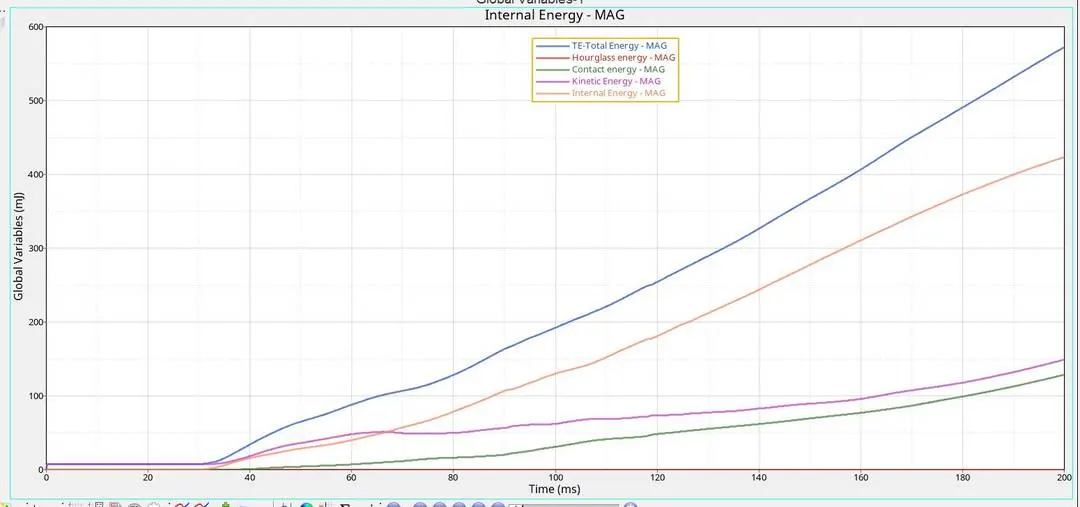
From the roof crash, the impactor gets in contact with the car at 35 ms, the energies are continuously in contact with the car so we can see the graph increasing till 200ms.
The kinetic energy is less compared to internal energy because we are using a quasi-static method. The hourglass energy is very less because we have used QEPH.
For four-node shell elements, radioss provides three types of element Q4, QBQT, QEPH usually the combination of integration which gives the best result with minimum investment is QEPH(Quadrilateral ElastoPlastic Physical Hourglass control).
The contact between the impactor and the car was 120 J till the end of the simulation and the total energy is increasing 580 J up to 200ms.
Force vs. Displacement:
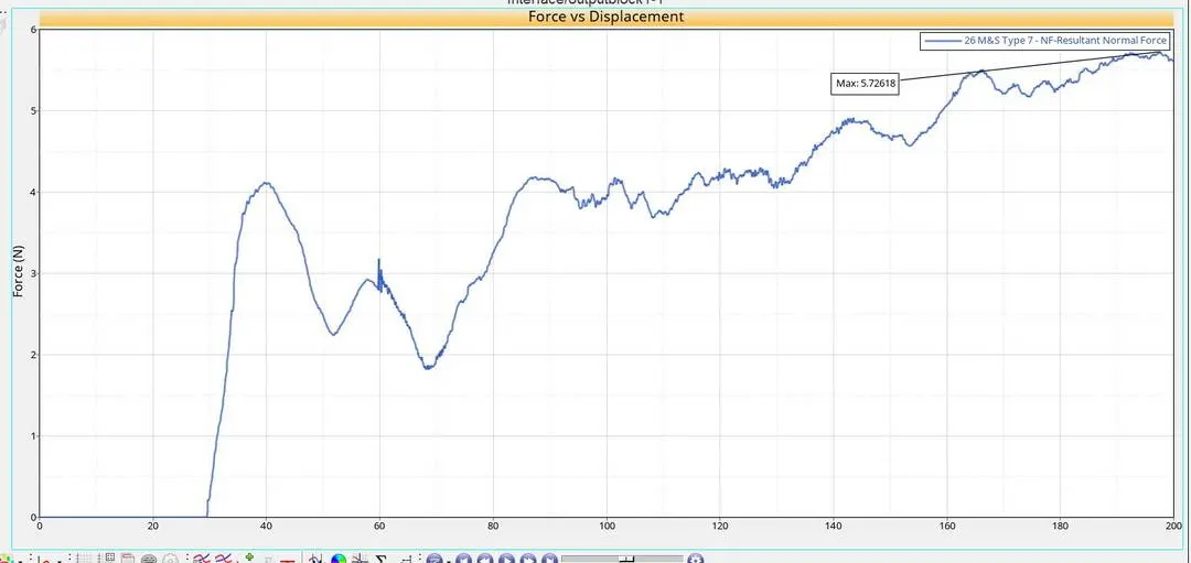
FMVSS 216 target load:
The total mass of the model is 159.75kg. As per the standard of FMVSS 216, the roof of the model should resist 3 times the force acting on the stationary model at rest.
Target load = 3*159.74*9.81 = 4701.1482 N = 4.7 KN
According to the force vs displacement, the maximum force resisted by the model was 5.7 KN.
Conclusion:
The frontal crash analysis is done with the student version of Hyperworks. The Improper meshing leads to some errors which are in an acceptable range.
We have obtained the value of the energies, force vs displacement and have created type 7 interface between impactor and car. Obtained the roof crash simulation with given parameters.
The B-pillar, rail and doors which are the component in the crash zone they absorb more energy but in this crash, the energy is transferred to passenger section that's why we can see deformation happening in the passenger compartment.

The energy error obtained as -18.4%, Mass error obtained is 0.2662E-03 No of cycles is 400000.
By improving the Components in the crash zone will help in protecting the occupants.
- The energy error and mass error are in an acceptable range.
- Since there are few flying components the energy error has increased.
- The B-pillar design also plays an important role in keeping the impact less transmitting to the interior parts of the vehicle.
- The position of the centre of gravity of the vehicle is vital in the crashworthiness, so maintaining the weight balancing of the vehicle is the skill of design engineer.
- As we are using the half model and with masses, if we can go for full vehicle body analysis then more realistic results can be obtained.
The maximum force resisted by the roof of the model was below the target load hence the roof of the car has failed to compile with the standards.
The reason behind the failure could be due to a lack of components available in the model.